
Related Manuals for CD Automation REVEX 1PH RX1 280 Series


Summary of Contents for CD Automation REVEX 1PH RX1 280 Series
- Page 1 USER’S MANUAL Rev. 05/2022 280A M-RX1-280 CD Automation S.r.l. Via Picasso, 34/36 - 20025 Legnano (MI)- Italy Tel. +39 0331 577479 - Fax +39 0331 579479 E-mail: info@cdautomation.com - Web: www.cdautomation.com...
- Page 2 Declaration of conformity Declaration of conformity-Dichiarazione di Conformità PRODUCT MANUFACTURER / PRODUTTORE: CD Automation S.R.L. Controllers, Drives & Automation Via Picasso, 34/36 - 20025 Legnano (MI)- Italy P.I. 08925720156 -Tel. +39 0331 577479 - Fax +39 0331 579479 E-mail: info@cdautomation.com - Web: www.cdautomation.com...
-
Page 3: Declaration Of Conformity
Declaration of conformity Declaration of conformity-Dichiarazione di Conformità PRODUCT MANUFACTURER / PRODUTTORE: CD Automation S.R.L. Controllers, Drives & Automation Via Picasso, 34/36 - 20025 Legnano (MI)- Italy P.I. 08925720156 -Tel. +39 0331 577479 - Fax +39 0331 579479 E-mail: info@cdautomation.com - Web: www.cdautomation.com... -
Page 4: Important Warnings For Safety
User’s manual REVEX 1PH 280A Important warnings for safety This chapter contains important information for the safety. The not observance of these instructions may result in serious personal injury or death and can cause serious damages to the Thyristor unit and to the components system included. - Page 5 User’s manual REVEX 1PH 280A WARNING! All service including inspection, installation, wiring, maintenance, troubleshooting, fuse or other user serviceable component replacement must be performed only by properly qualified personnel. Service personnel must read this manual before proceeding with work. While service is being performed unqualified personnel should not work on the unit or be allowed in the immediate vicinity.
- Page 6 User’s manual REVEX 1PH 280A AVERTISSEMENT! Au moment de relever des mesures de tension ou de courant en direct, utiliser un équipement de protection individuelle approprié pour les tensions et les potentiels d’arc électrique concernés. WARNING! Verify the voltage and current ratings of the power controller are correct for the application. AVERTISSEMENT! Vérifier que les valeurs de tension et de courant du régulateur de puissance sont correctes pour l’application.
-
Page 7: Maintenance
Substituted parts remain of Producer property. CD Automation srl assumes no liability for any damage to persons or property deriving from tampering, from incorrect or improper use, or from any use not conforming to the characteristics of the controller and to the instructions in this User Manual. -
Page 8: Table Of Contents
User’s manual REVEX 1PH 280A Summary Declaration of conformity ........3 Important warnings for safety . - Page 9 User’s manual REVEX 1PH 280A Using the Configurator........40 10.1 Typical Uses .
-
Page 10: Introduction
User’s manual REVEX 1PH 280A Introduction A thyristor unit is semiconductor device which acts as a switch formed by two thyristors in antiparallel. To switch on the alternating current the input signal will be on and the thyristor will switch off at first Zero Crossing voltage with no input signal. -
Page 11: Software Configurator
User’s manual REVEX 1PH 280A Software Configurator Thyristor configurator software is free and is possible download it from our site. If the Order Code is in line with requirement, then unit has been already configured in Factory and it’s ready to use. You need the software only to modify the ordered configuration. -
Page 12: Quick Start
User’s manual REVEX 1PH 280A Quick Start Attention: this procedure must be carried out by skilled people only. If your REVEX code is in line with what you really need, then the main configuration is already done by Producer and you just need to do the following steps: Verify REVEX current sizing. -
Page 13: Basic Connections And Sizing
User’s manual REVEX 1PH 280A Basic Connections and sizing Single phase wiring with resistive load I= P V V = Nominal voltage of the load I = Nominal current of the load P = Nominal power of the load Single phase wiring with inductive load I= P Vcosφ... -
Page 14: Identification And Order Code
User’s manual REVEX 1PH 280A Identification and Order Code 5.1 Identification of the unit Caution: Before to install, make sure that the Thyristor unit have not damages. If the product has a fault, please contact the dealer from which you purchased the product. The identification label give all the information regarding the factory settings of the Thyristor unit, this label is on the unit, like represented in figure. -
Page 15: Order Code
User’s manual REVEX 1PH 280A 5.2 Order Code REVEX 1PH CURRENT FUSES CONTROL MODE description description code note description code note 280A Fixed Fuses Included Open Loop Voltage MAX VOLTAGE Voltage Square description code note Current 480V Current Square 600V Power VxI External feedback MAIN SUPPLY VOLTAGE... -
Page 16: Technical Specifications
User’s manual REVEX 1PH 280A Technical Specifications 6.1 General features Cover and Socket material: PolymericV2 Utilization Category: AC-51 AC-55b IP Code: Method of Connecting: Single Phase Load Auxiliary voltage Order Code RX1___-_4: 24Vdc (1A) Relay output for Heater Break Alarm 0.5A a 125VAC (only with HB option) 6.2 Input features... -
Page 17: Derating Curve
User’s manual REVEX 1PH 280A 6.6 Derating Curve The nominal current of the units in specification are referred to continuous service at 40°C ambient temperature. For higher temperature multiply the nominal current times derating coefficient K below represented: l max = l nominal x K Derating For higher cabinet temperature... -
Page 18: Installation
User’s manual REVEX 1PH 280A Installation Before to install, make sure that the Thyristor unit have not AIR FLOW OUT (V) damages. If the product has a fault, please contact the dealer from which you purchased the product. Verify that the product is the same thing as ordered. -
Page 19: Dimensions And Weight
User’s manual REVEX 1PH 280A 7.1 Dimensions and weight REVEX 1PH Size: W (mm): D (mm): H (mm): Weight (kg): 6,50 7.2 Fixing holes 97 mm 97 mm... -
Page 20: Wiring Instructions
User’s manual REVEX 1PH 280A Wiring instructions The Thyristor unit could be susceptible to interferences lost by near equipments or by the power supply, for this reason in accord to the fundamental practices rules is opportune take some precautions: • The coil contactor, the relays and other inductive loads must be equipped with opportune RC filter. •... -
Page 21: Power Terminals
User’s manual REVEX 1PH 280A 8.5 Power Terminals Warning: Before connecting or disconnecting the unit check that power and control cables are isolated from voltage sources. Terminal Description Line Input Phase 1 Load Output Phase 1 8.6 Control Terminals Warning: Before connecting or disconnecting the unit check that power and control cables are isolated from voltage sources. -
Page 22: Schematic
User’s manual REVEX 1PH 280A 8.7 Schematic Indicative connection diagrams. Refer to local regulations for proper system protection. Warning: It is not possible to remove the M1 connector when the unit is powered. Remove the AUX 24Vdc power supply before extracting the M1 connector. Extracting the M1 connector with the AUX 24Vdc power supply connected to the M1 terminal could damage the unit L2/N... - Page 23 User’s manual REVEX 1PH 280A 8.7.1 SSR Control Input schematic For SSR input use follow the schematic below and configure Digital Input 1 as Fast Enable. Analog Input 1 INPUT * SSR Input: 4 ÷ 30Vdc 5mA Max (ON >4Vdc OFF <1Vdc) 3HZ Max on time min.
-
Page 24: Control Panel
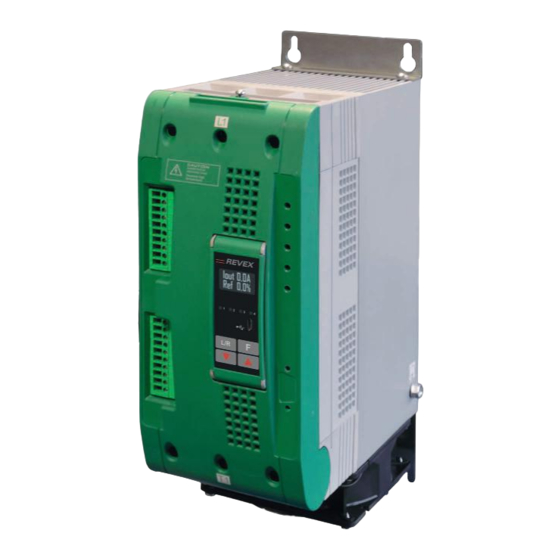
User’s manual REVEX 1PH 280A Control Panel Control Panel Display and Keys are Not present for Option Codes: 1/2/3/4/8/B/D/E (see table pag. 15) The Control Panel is placed on the front of the thyristor unit, on his display you can visualize the alarms, the input and output signals and all the configuration parameters. -
Page 25: Menu Navigation
User’s manual REVEX 1PH 280A 9.1 Menu navigation The menus are accessible using the control panel keypad and display. Control Panel Display and Keys are Not present for Option Codes: 1/2/3/4/8/B/D/E (see table pag. 15) Choose Enter Choose Edit HOME PAGE Menu Password Parameter... -
Page 26: Led Indicators
User’s manual REVEX 1PH 280A 9.2 Led indicators The four indicators on the control panel show the general state of the power controller. Power output set locally or via Flashing communications Aux High Local/Remote Power output set remotely (via SP 100% analog input) Output enabled Enable... -
Page 27: Parameter List
User’s manual REVEX 1PH 280A 9.4 Parameter list Control Panel Display and Keys are Not present for Option Codes: 1/2/3/4/8/B/D/E (see table pag. 15) This chapter describes the parameter on the menus accessed via the control panel and Configurator software. To learn how to access the menus described below see “Menu navigation”... - Page 28 User’s manual REVEX 1PH 280A 9.4.1 Operator Menu This section describes each item on the operator menu. Use this menu to view the measured values and basic settings of the power controller. The password to access this menu is 0. Modbus Par.
- Page 29 User’s manual REVEX 1PH 280A 9.4.2 Setup Menu This section describes each item on the setup menu. Use this menu to configure the power controller for the load. The password to access this menu is 2. Modbus Par. Parameter Name Description Range Unit...
- Page 30 User’s manual REVEX 1PH 280A 9.4.3 Advanced Setup Menu This section describes each item on the advanced setup menu. Use this menu to configure the power switching, closed loop control of power and adjustable settings for data logging and heater bakeout. The password to access this menu is 10.
- Page 31 User’s manual REVEX 1PH 280A Modbus Par. Parameter Name Description Default Range Unit Address Type Feedback Read Choose the feed-back type Write Option Description Value V² Voltage squared None No feed-back I² Current squared Voltage Voltage Current Current Power Power External External signal via analog input 2 DEFAULT: None...
- Page 32 User’s manual REVEX 1PH 280A Modbus Par. Parameter Name Description Default Range Unit Address Type HB Delay Set a delay between when the resistance drops below the value set 0 to 255 50 (2,5 Read for a heater break sensitivity and when (0 to 12,75 sec) Write...
- Page 33 User’s manual REVEX 1PH 280A 9.4.4 Hardware Menu This section describes each item on the hardware menu. Use this menu to configure how the inputs and outputs are used in the application. The password to access this menu is 5. Modbus Par.
- Page 34 User’s manual REVEX 1PH 280A Modbus Par. Parameter Name Description Default Address Type DI1 Functn Choose how the signal detected by digital input 1 Read is used Write Option Description Value Enable Enable power output V Feedback Use voltage feed-back when on Local / Rmt Local when on / Remote when off Ph Angle...
- Page 35 User’s manual REVEX 1PH 280A Modbus Par. Parameter Name Description Default Address Type Alm Out Fn Choose for which conditions the digital output indicates alarm. The output always indicate an alarm when the heat sink is over temperature. The digital output is energized for normal operating condition and de-energized when the power Read controller is off or when there is an alarm.
- Page 36 User’s manual REVEX 1PH 280A Modbus Par. Parameter Name Description Default Address Type IL SP Src Read Choose how the current limit is set 14, bit 4 Write Option Description Value Local / Comms Set point set via keypad or communication Analog In 2 Set point set via analog input DEFAULT: Local / Comms...
- Page 37 User’s manual REVEX 1PH 280A 9.4.5 Communication Menu This section describes each item on the communication menu. Use this menu to configure the communication options. The password to access this menu is 3. Modbus Par. Parameter Name Description Default Address Type Port 1 Baud Read...
- Page 38 User’s manual REVEX 1PH 280A 9.4.6 Monitoring Menu This section describes each item on the monitoring menu. Use this menu to view the states of digital input, values of analog input and information about the power controller such as serial number and software version. The password to access this menu is 0.
- Page 39 User’s manual REVEX 1PH 280A Modbus Par. Parameter Name Description Range Unit Address Type Analog In1 Indicates the percent of full scale measured Read 0 to 100.0 by analog input 1 Only Analog In2 Indicates the percent of full scale measured Read 0 to 100.0 by analog input 2...
-
Page 40: Using The Configurator
User’s manual REVEX 1PH 280A Using the Configurator Confi gurator software can be used like an alternative of the power controller’s keypad and set the advanced features not available via the power controller’s onboard user interface. Here we explain how to use it. 10.1 Typical Uses The software may be used during commissioning to: •... - Page 41 User’s manual REVEX 1PH 280A Procedure to communicate with a power controller: 1) if used direct USB connection: - Connect the USB cable between the computer and the micro USB connector on the power controller’s keypad - if necessary, wait for the USB driver to install.
-
Page 42: Using The Configurator
User’s manual REVEX 1PH 280A 10.5 Using the Confi gurator After software been installed, communication has been set up and model type selected, is possible to operate with the power controller. 10.5.1 To view or save a power controller’s settings using “Simple” view section: 1) Click Simple, if not already on the simple view 2) Click... - Page 43 User’s manual REVEX 1PH 280A 10.5.3 To download a recipe fi le into a power controller: 1) Click Simple, if not already on the Simple view 2) Click Open existing recipe 3) Locate and select the recipe fi le and click Open 4) Click 5) Click...
-
Page 44: Software General Information
User’s manual REVEX 1PH 280A 10.6 Software General information Here it is described the Confi gurator Software and how to use it. 10.6.1 Program Window Main Menu Access these menus. File menu Exit: close the program Setting menu Language: open Language Settings dialog Serial Port: open Serial Port dialog box Option: open General Option dialog box... - Page 45 User’s manual REVEX 1PH 280A Save: save the recipe in a fi le Save as: save a copy of the recipe in a fi le Download to unit: send the current recipe parameters in the connected power controller Print: print the recipe (see sample at right) Print report: print the recipe (see sample at right) To edit the actual recipe values click a parameter menu name:...
- Page 46 User’s manual REVEX 1PH 280A To confi gure and monitor the digital inputs: Digital input states and functions: show whether each input detects an open or closed circuit and the function the input performs. Digital Input States and Function Selectors: set the function for each digital input.
- Page 47 User’s manual REVEX 1PH 280A Confi gure and monitor the analog inputs: Analog Input 1: click Ai 1 to view the signal type Input Local/Remote selection button: click to toggle between using the signal received at analog input 1 (remote) or the slider (local) to set the set point. Reference: drag the slider, click the increment (+) or decrement (-) buttons or click one of the three percentages (0%, 50% or 100%) to set the set point when the set point source is set to local.
- Page 48 User’s manual REVEX 1PH 280A 10.6.4. Load Analyzer Load Analyzer is used for monitoring values graphically represented Click on Load Analyzer button on the test page to open Load Analyzer window. It’s possible to see 3 channels (Ch 1, Ch 2 and Ch 3).
- Page 49 User’s manual REVEX 1PH 280A 10.6.5 Live! Scope This view provides a graph of current waveform over a few sample cycles. Data will be automatically updated when Enable will be selected. Use these options to confi gure the displayed data: Enable: set this option to view the current on the graph Save: click to save a JPEG image...
- Page 50 User’s manual REVEX 1PH 280A 10.6.6 MSG view Message view shows the communication activity between the computer and the power controller. PORT COM: use this view to see when the COM port is accessed and its settings MODBUS: Modbus communication protocol area READ Area: use this view to see parameters being polled READ Area ->...
-
Page 51: Configurable Inputs And Outputs
User’s manual REVEX 1PH 280A Configurable Inputs and Outputs The REVEX power controller features two digital inputs, up to two analog inputs and a relay output. Some models also include an analog output for retransmitting a measured value to other automation equipment. This section describes the various functions of these inputs and outputs and how they interact with other features of the power controller. -
Page 52: Analog Input 2: Set Point, Feedback Or Current Limit Set Point
User’s manual REVEX 1PH 280A 11.3 Analog Input 2: Set Point, Feedback or Current Limit Set Point What this input does is user-configurable. Connect an analog signal that indicates: • An alternate set point signal • Measured power, voltage or current from an external device used as feedback •... -
Page 53: Alarm Description
User’s manual REVEX 1PH 280A Alarm description 12.1 Heater Break Alarm This option allows you to diagnose any load breakage. The diagnostics is based on the comparison of the value of the nominal resistance of the load with respect to the resistance measured in real time. The nominal resistance is calculated using the Operative Load Voltage (Nom Line V) and Nominal Current of the load (Nominal I) parameters. -
Page 54: Aux High
User’s manual REVEX 1PH 280A 12.2. AUX High This alarm is displayed when the auxiliary supply voltage exceeds the established ranges. If the alarm situation persists for more than 5 seconds, the unit will go into protection. 12.3 AUX Low This alarm is displayed when the auxiliary supply voltage is lower than the established ranges. -
Page 55: Firing Type
User’s manual REVEX 1PH 280A Firing type Choose a correct firing type allows to optimize the thyristor unit for the installed load. The firing type has already configured in line with customer requirements that are defined in the Order Code. The Order Code is written on the identification label. -
Page 56: Soft Start With Burst Firing
User’s manual REVEX 1PH 280A 13.4 Soft Start with Burst Firing This is an additional function to the Burst Firing. The unit start in phase angle mode with a ramp starting from Voltage Supply (V) zero up to the full tension in the cycles number set in the parameter. -
Page 57: Delay Triggering With Burst Firing
User’s manual REVEX 1PH 280A 13.7 Delay Triggering with Burst Firing The Delay Triggering firing is used Without Delay Triggering With Delay Triggering the control a primary of transformer coupled with normal resistances on the secondary (N.B. Transient over-current don’t connect cold resistances on Delay angle the secondary like: Superkanthal, (0°... -
Page 58: Heater Bakeout Function
User’s manual REVEX 1PH 280A Heater bakeout function When a heater insulated with magnesium oxide (MgO) is powered off, not in use or in storage for a long period of time, it can absorb moisture. If full power is applied, excessive current can damage the heater or blow fuses. The heater bakeout feature limits the voltage and current applied as the heater is brought back in to service. -
Page 59: Control Mode (Feed-Back)
User’s manual REVEX 1PH 280A Control Mode (feed-back) The Control Mode (feed-back) type has already configured in line with customer requirements that are defined in the Order Code. The Order Code is written on the identification label. However, if you wish to change the Control Mode (feed-back) type you can use the software configurator or the Control Panel. -
Page 60: Electronic Boards
User’s manual REVEX 1PH 280A Electronic boards 16.1 Supply the Electronic Board The REVEX thyristor unit, to work, requires a voltage supply for the electronic boards of 24Vdc 1A on Terminal M1 (5, 6) and the Synchronization signal between terminals 1 and 3. The voltage used on Terminal 1 and 3 must be the same of load voltage (L1-L2/N). -
Page 61: Rs485 Serial Port
User’s manual REVEX 1PH 280A RS485 Serial port Terminal M1 Description The serial communication port RS485 is available on the RS485 A+ Command Terminals. On this port may be done a network up to 127 REVEX. RS485 B- 17.1 FIELD BUS Module Technical Specification •... -
Page 62: Internal Fuse
User’s manual REVEX 1PH 280A Internal Fuse The thyristor unit have internal fuse extrarapid at low I²T for the thyristor protection of against the short-circuits. The Fuses must have I²T 20% less than thyristor’s I²T. The warranty of thyristor is null if no proper fuses are used. 200 kA Symmetrical A.I.C. - Page 63 CD Automation S.r.l. Via Picasso, 34/36 - 20025 Legnano (MI)- Italy Tel. +39 0331 577479 - Fax +39 0331 579479 E-mail: info@cdautomation.com - Web: www.cdautomation.com...
Need help?
Do you have a question about the REVEX 1PH RX1 280 Series and is the answer not in the manual?
Questions and answers