Advertisement
Quick Links
Advertisement

Related Manuals for Jakka CONTROL KIT 5

Summary of Contents for Jakka CONTROL KIT 5
- Page 1 JAKKA CONTROL KIT 5 USER MANUAL...
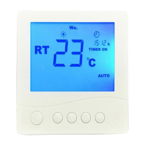
- Page 2 1. ROOM THERMOSTATE 3.1” Screen 6 Steps control of exhaust and supply fans Working of the unit in Automatic/Manual Modes Heating/Cooling /Fan Modes Room Temperature Sensor User Friendly Design Minimum ve Maximum Set Temperature Limit Constant HVAC-R Images Weekly Programming...
-
Page 3: Control Panel
2. CONTROL PANEL Control Panel Control Panel run the heat recovery units by controlling supply and exhaust fans seperately and controlling electrical heater in steps.. It is also possible to control pre and after heater, fresh air damper, bypass damper, ,heating coil, cooling coil and also EC fans Main Features: Filter Alarm According to Pre-set Time counter (Pre-set Service Time) Pre programmed scenario selection via room thermostate... -
Page 4: Specifications
3. SPECIFICATIONS Environmental Specs Functional Specs Working and Storage Temperature: 0 ... +50°C On/ Off via BMs Protection Class: EN 60529 - IP00 Embedden temperature sensor to room thermostate Control Of; Electrical Specs Duct Type Temperature Sensor Fresh Air Damper Control : Room Thermostate/BMS Bypass Air Damper... - Page 5 FEATURES OF ROOM THERMOSTATE: A. ) HOW TO MAKE WEEKLY PROGRAMMING: • Press button for two (2) seconds while the unit is on. You will see “00” at the upper-right part of the screen, then press • Mode / OK button.
- Page 6 E.) HOW TO ACTIVATE KEYLOCK: • Press DOWN buttons simultaneously when the unit is on. There will be a lock symbol on screen after 2 seconds. All of the buttons will be locked when keylock is on. F.) HOW TO DEACTIVATE KEYLOCK: •...
- Page 7 I.) ENTERING TO SERVICE MENU: To Enter: • Press DOWN buttons simultaneously • Enter service menu password by using DOWN and press Mode/OK. Note: The Service menu password is“58” • Then go to Parameter you want to change by using DOWN buttons then press Mode/OK...
- Page 8 J.) SELECTING TEMPERATURE CONTROL POINT There are 4 options that unit can check the temperature; -Room thermostate -Return Air -Supply Air -Outside Air To select one of these; • Press DOWN buttons simultaneously • Enter service menu password by using DOWN and press Mode/OK.
- Page 9 K. SETTING FAN STEP PARAMETERS STEPKADEME AYARI Each 6 steps of supply and exhaust fans could be set seperately.. To set step value of the fans • When the unit is connected to power supply , press DOWN buttons simultaneously •...
- Page 10 L. SETTING FRESH AIR DAMPER OPENING TIME • When the unit is connected to power supply , press DOWN buttons simultaneously “58” • Enter service menu password by using DOWN and press Mode/OK. • Go to parameter ‘’199’’ by using DOWN and press Mode/OK.
-
Page 11: Error Codes Trouble Shooting
ERROR CODES TROUBLE SHOOTING CODE EXPLANATION 0001 Exhaust Fan Error Check the fan,connection cables and filter.If 11lla re fine, reset the alarm by pressing buttons simultaneously If there is a broken component replace it with a new one. 0002 Supply Fan Error Check the fan,connection cables and filter.If 11lla re fine, reset the alarm by pressing buttons... -
Page 12: Modbus Register List
[Buraya yazın] MODBUS – RTU SETTINGS SESESETTINGSI Enter to Sevice Menu as it is described above (I. Entering To Service Menu) For Modbus ID’s go to parameter 111 . Go to Modbus ID by using • DOWN buttons Set and confirm by using Mode/Ok For Modbus Baudrate go to parameter 112 and change Modbus Baudrate by using DOWN... - Page 13 [Buraya yazın] 4022 Exhaust Fan Thermal Error Info 0...1 Exhaust Fan Error Info 4023 Supply Fan Thermal Error Info 0...1 Supply Fan Error Info 4024 Emergency Stop Button Info 0...1 Emergency Stop Button Info 4025 Low Pressure Info 0...1 Low Pressure Info Hıgh Pressure Info Hıgh Pressure Info 4026...
- Page 14 [Buraya yazın] 4070 Proportional ByPass Damper Exit Value 0...100 4071 Mixing Damper Exit Value 0...100 4072 VRF Exit Value 0...100 Weekly Programming Parameter Registers 4073 Sunday Starting Time Hour/Minute 0...2359 Unit works between starting and stopping 4074 Sunday Stopping Time Hour/Minute 0...2359 time.
- Page 15 [Buraya yazın] 4111 Service Setting Password 0...9999 Main card password is "58" Building Management Modbus-RTU Parameters 4112 Modbus ID 1...254 4113 Modbus Baudrate 0...7 Screen Value Registers 0:Do Not Show 1:OutsideTemperature 4114 Show Temperature Value 0...3 2:Supplied Air Temperature 3:Show both temperatures 0:Do not show 1:CO2 4115...
- Page 16 [Buraya yazın] 4136 Exhaust Fan 5. Step Value 4137 Exhaust Fan 6. Step Value 4138 Supply Fan 0. Step Value 4139 Supply Fan 1. Step Value 4140 Supply Fan 2. Step Value It is recommended not to work motor , at a value of exit voltage under 120 V.
- Page 17 [Buraya yazın] 4171 Max. Temperature Value for defrost -400...999 4172 Max.Defrost Period 1...100 1…100 4173 Waiting Time between two defrosts Frost Protection Setting Parameters 4174 Heating Coil min Temp. Value in case of Frost -400...999 4175 Heating Coil max. Temp. Value in case of Frost -400...999 4176 Exchanger min Temp.
- Page 18 Digital OutputCheck Parameters 4202 Number 1 Digital Output 0...1 4203 Number 2 Digital Output 0...1 4204 Number 3 Digital Output 0...1 4205 Number 4 Digital Output 0...1 4206 Number 5 Digital Output 0...1 4207 Number 6 Digital Output 0...1 4208 Number 7 Digital Output 0...1 4209...
- Page 19 4256 Number 15 Universal Input Calibration -9999...9999 4257 Number 16 Universal Input Calibration -9999...9999 4258 Number 17 Universal Input Calibration -9999...9999 4259 Number 18 Universal Input Calibration -9999...9999 4260 Number 19 Universal Input Calibration -9999...9999 Universal On/Off Selection Setting Parameters Uın1 Input On/Off Selection 4262 Uın2 Input On/Off Selection...
- Page 20 Dın7 Output On/Off Selection 4308 Dın8 Output On/Off Selection 4309 Dın9 Output On/Off Selection 4310 Dın10 Output On/Off Selection 4311 Dın11 Output On/Off Selection 4312 Dın12 Output On/Off Selection 4313 Dın13 Output On/Off Selection 4314 Dın14 Output On/Off Selection 4315 Dın15 Output On/Off Selection 4316 Dın16 Output On/Off Selection...
- Page 21 4359 Analog Output 8 Maximum Value -9999...9999 4360 Analog Output 9 Maximum Value -9999...9999 Modbus Parameters 4361 Modbus Data 0...1 4362 Modbus Parity 0...1 4363 Modbus Stop 0...1 Auto Mode Dead Area Setting Parameters 4364 Auto Mod Cooling Dead Area 0...999 4365 Auto Mod Heating Dead Area...
- Page 22 Applications Digital Output Selection Parameters 4421 Exhaust Fan Exit Number 4422 Supply Fan Exit Number 4423 After El.Heater Exit Number 4424 Pre El. Heater Exit Number 4425 Fresh Air Damper On Exit Number 4426 Fresh Air Damper Off Exit Number 4427 ByPass Damper On Exit Number 4428...
- Page 23 R. PRE-PROGRAMMED HEAT RECOVERY SCENARIOS There are 16 preprogrammed sceanarios embedded to electronical card; 1. Standard Heat Recovery 2. Heat Recovery with 3 Steps Electrical Heater (With Fresh Air Damper) 3. Heat Recovery with 3 Steps Electrical Heater (With By-Pass Damper) 4.
- Page 24 1. Standard Heat Recovery Scenario In this scenario, unit supplies fresh air to environment and exhaust stall air. This scnario has only manual mode. Supply and exhaust fans can be set seperately in 6 different speeds via room thermostate . Room thermsotate shows temperature of inner space where it is already located.
- Page 25 Advanced Heat Recovery with 3 Steps Electrical Heater Scenario (With By-Pass Damper) In this mode; exhaust and supply fans and after heater can be controlled. Temperature is measured by room thermostate • If room temperature is measured below set value, temperature will be increased by using after heater •...
- Page 26 Notes; The electrical board comes with Scenario Number 4 as default. To change the scenario please follow the steps defined in ‘’S.Changing the Scenarios’’ When Scenario 5 is selected , unit is ready to work as Heat Recovery with 1 Step Pre heater 2 Steps After Heater . Default Values for Pre Heater;...
- Page 27 6. HEAT RECOVERY WITH 2 STEPS PRE-HEATER 1STEP Scenario AFTER AFTER HEATER Heat Recovery with 2 Steps Pre Heater 1 Step After Heater mode works according to set temepareture and control exhaust ans supply fans and after heater. Pre-heater works according to fresh air sensor. Temperature is measured by room thermostate •...
- Page 28 7. HEAT RECOVERY WITH 3 STEPS PREHEATER Scenario Heat Recovery with 3 Steps Pre Heater mode works according to set temepareture and control exhaust ans supply fans and pre heater. Pre-heater works according to fresh air sensor. • The fresh air temperature read by NtC10K sensor will be compared with set value of pre-heater to open or shut down pre-heater.
Need help?
Do you have a question about the CONTROL KIT 5 and is the answer not in the manual?
Questions and answers