Table of Contents
Advertisement
Quick Links
Advertisement
Table of Contents

Related Manuals for Planet WGD-800


Summary of Contents for Planet WGD-800
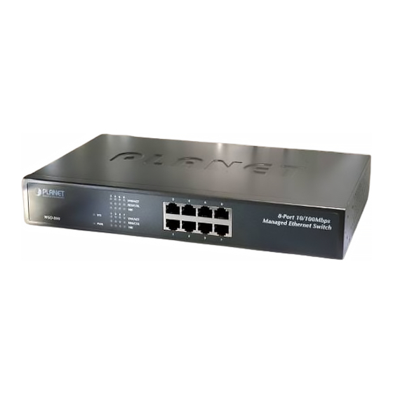
- Page 1 User's Manual WGD-800 8-Port 10/100Mbps Managed Ethernet Switch...
- Page 2 Trademarks Copyright © PLANET Technology Corp. 2005. Contents subject to which revision without prior notice. PLANET is a registered trademark of PLANET Technology Corp. All other trademarks belong to their respective owners. Disclaimer PLANET Technology does not warrant that the hardware will work properly in all environments and applications, and makes no warranty and representation, either implied or expressed, with respect to the quality, performance, merchantability, or fitness for a particular purpose.
-
Page 3: Table Of Contents
PECIFICATION 2. INSTALLATION ... 9 2.1 P ... 9 RODUCT ESCRIPTION 2.1.1 Product Overview ... 9 2.1.2 Switch Front Panel ... 9 2.1.3 LED Indications ... 9 2.1.4 Switch Rear Panel...10 2.2 I ...10 NSTALL THE WITCH 2.2.1 Desktop Installation ...10 2.2.2 Rack Mounting ... - Page 4 4.4.8 Load Default ...30 4.4.9 Reboot ...30 4.5 P ...30 ANAGEMENT 4.5.1 Port Configuration ...30 4.5.2 Port Statistics...31 4.5.3 Port Band Restrict ...31 4.6 R ...32 EDUNDANCY 4.6.1 Spanning Tree ...32 4.6.2 Spanning Tree Configuration...38 4.6.3 Link Aggregation...40 4.7 S ...41 ECURITY 4.7.1 VLAN ...41...
- Page 5 6.2 100BASE-TX/10BASE-T P ...86 SSIGNMENTS 7. APPENDIX-B ...87 802.1Q VLAN M VLAN 1 ...87 ULTI NTAGGED SETTING SAMPLE...
-
Page 6: Introduction
The chapter explains how to trouble shooting of the Switch. Chapter 6, APPENDIX The chapter contains cable information of the Switch. In the following section, terms "SWITCH" with upper case denotes the WSD-800 Ethernet switch. Terms with lower case "switch" means any Ethernet switches. 1.3 Product Feature ▫... -
Page 7: Product Specification
1 to many Ingress/Egress Port mirror and Port analysis ▫ Broadcast/Multicast/Flooded storm control ▫ 802.1X Port-Based Authentication ▫ IP Stack Technology supports up to 8unit switch stack for centralize management 1.4 Product Specification Hardware Specification Network Connector RS-232 connector Switch architecture... - Page 8 Management Interface Console/Web/Telnet/SNMP SNMP Version v1, v2c Support MIB Support SNMP MIBⅡ(RFC 1213), Bridge MIB (RFC 1493), RMON group 1,2,3,9 Enterprise private MIB Standard Compliance Network Standard IEEE802.3 10Base-T IEEE802.3u 100Base-TX IEEE802.3x Flow Control and Back pressure IEEE802.3ad Port trunk with LACP IEEE802.1d Spanning tree protocol IEEE802.1w Rapid Spanning Tree IEEE802.1p Class of service...
-
Page 9: Installation
This section describes the functionalities of the Switch's components and guides how to install it on the desktop or shelf. Basic knowledge of networking is assumed. Please read this chapter completely before continuing. 2.1 Product Description 2.1.1 Product Overview With 8-Port 10/100Mbps TP, the PLANET WSD-800 boasts a high performance switch architecture that is capable of providing non-blocking switch fabric and wire-speed throughput as high as 1.6Gbps. -
Page 10: Switch Rear Panel
Step4: Connect the Switch to network devices. A. Connect one end of a standard network cable to the 10/100/1000 RJ-45 ports on the front of the Switch B. Connect the other end of the cable to the network devices such as printer servers, workstations or routers…etc. -
Page 11: Rack Mounting
Step3: Secure the brackets tightly. Step4: Follow the same steps to attach the second bracket to the opposite side. Step5: After the brackets are attached to the Switch, use suitable screws to securely attach the brackets to the rack, as shown in Figure 2-6 Figure 2-6 Mounting the Switch in a Rack Step6: Proceeds with the steps 4 and steps 5 of session 2.2.1 Desktop Installation to connect the network cabling... -
Page 12: Console Management
The console port is a female DB-9 connector that enables a connection to a PC or terminal for monitoring and configuring the Switch. Use the supplied RS-232 cable with a male DB-9 connector to connect a terminal or PC to the Console port. -
Page 13: Console Management
“enable” for further configuration. The system needs password for further configuration. After the “enable” command, the system asks for password, please enter “admin” for the default password. As shows in the following screen: Console login screen 3.3 Console Management Entering a question mark "?" at the prompt displays the list of commands available for command mode. As shows in the following screen: The question mark “?”... -
Page 14: Telnet Login
3.4 Telnet login The switch also supports telnet for remote management. The switch asks for user name and password for remote login when using telnet, please use “admin” for username and “admin” for password. 3.5 Commands There are two levels for console commands. The first level provides commands to show system informations and current configurations. -
Page 15: Privileged Command
To access to the second level, enter the “enable” command in the first level. The sysem then prompt for a password. Please enter “password” for the password. The promt then changes to “Switch\enable>”. Entering a question mark "?" at the prompt displays the list of commands available for command mode. -
Page 16: Copy Command
clear mirror monitored-port ingress clear multicast router clear port counters clear port rate-shaping clear port spantree portcost clear port spantree portpri clear port storm-limit clear qos map cos-queue-map clear qos map dot1p-cos-map clear qos map mac-cos-map clear qos map vlan-cos-map clear radius key clear security filter-MAC clear security static-MAC... -
Page 17: Disable Command
Reboot command is to reboot the switch, please beware to check if the configuration is saved.. Command Reboot 3.5.2.5 Set command Set command is to change the parameter of the switch functions. The follow table lists the set commands and the equivalent usages. Command set channel... - Page 18 set igmp-snooping group number set igmp-snooping group policy set igmp-snooping immediate-leave set igmp-snooping policy deny set ip http server disable set ip http server enable set ip telnet server disable set ip telnet server enable set ipstack enable set ipstack disable set ipstack group set ipstack mac-addr set ipstack mode...
- Page 19 set qos map cos-queue-map set qos map dot1p-cos-map set qos map mac-cos-map set qos map port-cos-map set qos map vlan-cos-map set qos queue egress-policy set radius key set radius server set rstp force-version set security MAC-aging set security filter-MAC set security mac-learning set security static-MAC set snmp set snmp community...
-
Page 20: Show Command
3.5.2.6 Show command Show command is to display the current parameter of the switch functions. The follow table lists the show commands and the equivalent usages. Command show channel show console-info show dot1x local-userInfo... - Page 21 show security mac-learning show security static-MAC show snmp show snmp rmon show spantree show syntax show system show trunk show version show vlan show vlan type Show port security status Show static mac table information Show snmp information Show snmp rmon state Show spanning tree information Show basic help infomation Show system information...
-
Page 22: Web-Based Management
4.2 Preparing for Web Management Before use web management, you can use console to login the Switch checking the default IP of the Switch. Please refer to Console Management Chapter for console login. If you need change IP address in first time, you can use console mode to modify it. -
Page 23: System
The switch can be managed by the Web/Telnet/SNMP interfaces. Administrators can access the management interface via the IP address of the switch. The default IP address of the switch is 192.168.0.100. You can change the IP address to be in the same IP segment as your LAN network for convinence. -
Page 24: Snmp
2. The changed IP address take effect immediately after click on the OK button, you need to use the new IP address to access the Web interface. 3. The changed IP address remains the original after reboot the switch unless the configuration is saved. To save the changed IP address, please move to System/Saving Parameters menu. -
Page 25: Snmp Configuration
2. System Options This table is to define the system name, system location and the contact person of the switch. These informations show in the SNMP software of the management workstation which helps to identify the switch that is looking into. - Page 26 Use this table to configure the SNMP community strings and define the policy of the relative string. The community string acts like a password to permit access to the agent on the Switch. One or more of the following characteristics can be associated with the community string: Add Community: enter private or public 。...
-
Page 27: Password
A trap manager is a management station (SNMP application) that receives traps (the system alerts generated by the switch). If no trap manager is defined, no traps are issued. Create a trap manager by entering the IP address of the station and a community string. -
Page 28: Console
4.4.4 CONSOLE This function shows the connection parameters for the Console Management Interface. Click on the System/CONSOLE menu button, and the following table shows in the main page of the web. 4.4.5 System Upgrade This function allows performing firmware update from the web interface. Click on the System/System Upgrade menu button, and the following table shows in the main page of the web. -
Page 29: Saving Parameters
CAUTION: 4.4.6 Saving Parameters It takes effect immediately when you change the parameters of the management function when the switch is running. But the parameters would not be saved after reboot the swith. To keep the changed parameters, Click on the System/Saving Parameters menu button, and click on the “Save”... -
Page 30: Load Default
4.4.8 Load Default This function is to reset the configuration of switch to the factory default. Click on the System/Load Default menu button, and the following table shows in the web main page. CAUTION: This operation will result in all the parameters losing. -
Page 31: Port Statistics
4.5.2 Port Statistics The Port Statistics page provides a view of the current status of every port on the Switch. Pressing the “Reset” button will reset all port counters to zero. 4.5.3 Port Band Restrict The function provides the In-Band and Out-Band connection speed restriction on the ports. The Band of the connection speed rangs from 64Kbps to 80000Kbps. -
Page 32: Redundancy
It is possible to cause serious degradation of the performance of the network if the Spanning Tree is incorrectly configured. Please read the following before making any changes from the default values. The Switch STP performs the following functions:... - Page 33 Creating a Stable STP Topology It is to make the root port a fastest link. If all switches have STP enabled with default settings, the switch with the lowest MAC address in the network will become the root switch. By increasing the priority (lowering the priority number) of the best switch, STP can be forced to select the best switch as the root switch.
- Page 34 From disabled to blocking 。 You can modify each port state by using management software. When you enable STP, every port on every switch in the network goes through the blocking state and then transitions through the states of listening and learning at...
- Page 35 STP Operation Levels The Switch allows for two levels of operation: the switch level and the port level. The switch level forms a spanning tree consisting of links between one or more switches. The port level constructs a spanning tree consisting of groups of one or more ports.
- Page 36 BPDU packets sent by the Root Bridge to tell all other Switches that it is indeed the Root Bridge. If you set a Hello Time for your Switch, and it is not the Root Bridge, the set Hello Time will be used if and when your Switch becomes the Root Bridge.
- Page 37 STP assistance is not applied. If switch A broadcasts a packet to switch B, switch B will broadcast it to switch C, and switch C will broadcast it to back to switch A ... and so on. The broadcast packet will be passed indefinitely in a loop, potentially causing a network failure.
-
Page 38: Spanning Tree Configuration
LAN 2 The switch with the lowest Bridge ID (switch C) was elected the root bridge, and the ports were selected to give a high port cost between switches B and C. The two (optional) Gigabit ports (default port cost = 4) on switch A are connected to one (optional) Gigabit port on both switch B and C. - Page 39 True - This port connected directly to a end-node device or LAN segment where a loop cannot be 。 created False – This port connected to one or more LAN segments – maybe a ethernet switch or HUB, that a 。 loop might be occured P2P Status: Enables or disables the device to establish a point-to-point link, or specifies for the device to automatically establish a point-to-point link.
-
Page 40: Link Aggregation
128.The lower number has the highest priority. Path Cost: Specifies the path cost of the port. The switch uses this parameter to help determine which port will become a forwarding port. Lower numbers will be used as forwarding ports first. The range is from 0 to 65535. The default values based on IEEE802.1D are: 10Mb/s = 50-600, 100Mb/s = 10-60, 1000Mb/s = 3-10... -
Page 41: Security
It allows a maximum of four ports to be aggregated at the same time and up to 4 groups. If the group is defined as a LACP static link aggregationing group, then any extra ports selected are placed in a standby mode for redundancy if one of the other ports fails. - Page 42 A weighted round robin system is employed on the Switch to determine the rate at which the queues are emptied of packets. The ratio used for clearing the queues is 4:1. This means that the highest priority queue, Queue 1, will clear 4 packets for every 1 packet cleared from Queue 0.
- Page 43 Port-based VLAN Port-based VLAN limit traffic that flows into and out of switch ports. Thus, all devices connected to a port are members of the VLAN(s) the port belongs to, whether there is a single computer directly connected to a switch, or an entire department.
- Page 44 (and indeed, the entire network – if all network devices are 802.1Q compliant). Every physical port on a switch has a PVID. 802.1Q ports are also assigned a PVID, for use within the switch. If no VLAN are defined on the switch, all ports are then assigned to a default VLAN with a PVID equal to 1. Untagged packets are assigned the PVID of the port on which they were received.
-
Page 45: Vlan Configuration
VID for tagged packets, tag-aware and tag-unaware network devices can coexist on the same network. A switch port can have only one PVID, but can have as many VID as the switch has memory in its VLAN table to store them. - Page 46 3. The Port-base VLAN Confirutation table then pops up, enter the VLAN group ID, VLAN name and select the member ports for the VLAN. 4. Click the “OK” button to add the VLAN. 5. Select the ports in the Port List field and click on the Add button to add the member ports to the VLAN. The selected VLAN member then shows in the VLAN Member field.
- Page 47 802.1Q VLAN Configuration There are up to 256 configurable VLAN groups. By default when 802.1Q is enabled, all ports on the switch belong to default VLAN (VID 1). The default VLAN cannot be deleted. Understand nomenclature of the Switch Tagging and Untagging Every port on an 802.1Q compliant switch can be configured as tagging or untagging.
- Page 48 Set the port VLAN ID that will be assigned to untagged traffic on a given port. This feature is useful for accommodating devices that you want to participate in the VLAN but that don’t support tagging. The Switch allows each port to set one PVID, the range is 1~255, default PVID is 1. The PVID must be the same as the VLAN ID that the port was defined as belonging to in the VLAN group, or the untagged traffic will be dropped.
- Page 49 3. Choose the Link Type in the drop drop down menu: Access , Always Untag or Trunk. Note that if the Access type is chosen, it will strip the 802.1Q tag from all packets that out of this port. On the other hand, if the Trunk type is chosen, it will put the VID number, priority and other VLAN information into the header of all packets that out of this port.
-
Page 50: Mac Address Bind
4.7.2 MAC Address Bind This function is based upon for the switch security. When you add one MAC Address is bind with one port. It remains in the switch's address table, regardless of whether the device is physically connected to the switch. This... -
Page 51: Mac Address Filtering
Show MAC Address Table. 4.7.3 MAC Address Filtering MAC address filtering allows the switch to drop unwanted traffic. Traffic is filtered based on the destination addresses. To filter the MAC Address, click on the Security/MAC Address Filtering menu button, the main web page then shows the MAC Address Filtering function table. -
Page 52: Mac Address Learning
Current Filtering MAC Table. 4.7.4 MAC Address Learning The switch is able to disable MAC Address learning function on ports. 1. Fill the Port List field in the MAC Address Learning table and select Enable/Disable in the MAC Address Learning field. -
Page 53: Mac Address Aging Time
4.7.5 MAC Address Aging Time The Aging Time affects the learning process of the Switch. Dynamic forwarding table entries, which are made up of the source and destination MAC addresses and their associated port numbers, are deleted from the table if they are not accessed within the aging time. -
Page 54: 802.1X Port-Based Network Access Control
The IEEE 802.1X standard defines a client-server-based access control and authentication protocol that restricts unauthorized clients from connecting to a LAN through publicly accessible ports. The authentication server authenticates each client connected to a switch port before making available any services offered by the switch or the LAN. - Page 55 Authentication server—performs the actual authentication of the client. The authentication server validates the identity of the client and notifies the switch whether or not the client is authorized to access the LAN and switch services. Because the switch acts as the proxy, the authentication service is transparent to the client.
- Page 56 Ports in Authorized and Unauthorized States The switch port state determines whether or not the client is granted access to the network. The port starts in the unauthorized state. While in this state, the port disallows all ingress and egress traffic except for 802.1X protocol packets.
- Page 57 If a client that does not support 802.1X is connected to an unauthorized 802.1X port, the switch requests the client's identity. In this situation, the client does not respond to the request, the port remains in the unauthorized state, and the client is not granted access to the network.
- Page 58 4.7.6.2 802.1X Configuration This switch has two 802.1X Mode: Radius Server & Local Authenticate, choose one you need ● Local Authenticate — In this situation, do not need Radius server in the network, all authentication completed by 802.1x Switch,the normal topologies as below 1.
- Page 59 Force unauthorized: causes the port to remain in the unauthorized state, ignoring all attempts by the client 。 to authenticate. The switch cannot provide authentication services to the client through the interface. Maximum account number: the biggest user's quantity of passing authentication under this port, set 1,...
- Page 60 ● Radius Server — In this situation, need a Radius server in the network, the normal topologies as below Select the “Radius Server” mode. The RADIUS Server configuration table includes the following fields:...
- Page 61 IP Address of the Web-Smart switch with 192.168.0.100. And also make sure the shared secret key is as same as the one you had set at the switch RADIUS server – 12345678 at this case. The IP address of the RADIUS server being added.
- Page 62 Set the Ports Authenticate Status to “Force Authorized” if the port is connected to the RADIUS NOTE: server or the port is a uplink port that is connected to another switch. Or once the 802.1X stat to work, the switch might not be able to access the RADIUS server.
- Page 63 to be created on the Radius Server PC. For example, the Radius Server founded on Win2000 Server, and then: Enter ” Active Directory Users and Computers”, create legal user data, the next, right-click a user what you created to enter properties, and what to be noticed:...
-
Page 64: X Client Configuration
The following procedures show how to configure 802.1X Authentication in Windows XP. Please note that if you want to change the 802.1x authentication type of a wireless client, i.e. switch to EAP-TLS from EAP-MD5, you must remove the current existing wireless network from your preferred connection first, and add it in again. - Page 65 Select “Authentication” tab. Select “Enable network access control using IEEE 802.1X” to enable 802.1x authentication. Select “MD-5 Challenge” from the drop-down list box for EAP type. Click “OK”. When wireless client has associated with WGSW-2840/5240, a user authentication notice appears in system tray.
- Page 66 Enter the user name, password and the logon domain that your account belongs. 10. Click “OK” to complete the validation process.
-
Page 67: Qos
Classifier-classifies the traffic on the network. Traffic classifications are determined by protocol, application, source, destination, and so on. You can create and modify classifications. The Switch then groups classified traffic in order to schedule them with the appropriate service level. -
Page 68: Qos Configuration
Define a service level to determine the priority that will be applied to traffic. Apply a classifier to determine how the incoming traffic will be classified and thus treated by the Switch. Create a QoS profile which associates a service level and a classifier. - Page 69 2. VLAN-COS Mapping QoS settings allow customization of VLAN ID to Traffic classifiers Fill the VID (1-2094) field in the VLAN-CoS Mapping Table. Fill the mapping number in the CoS (0-7) field. Click on the “OK” button to save. To remove the VLAN-CoS mapping item, simply click on the “Delete” button in the Show VLAN-CoS Mapping table.
- Page 70 3. 802.1p-CoS Mapping QoS settings allow customization of packet priority in order to facilitate delivery of data traffic that might be affected by latency problems. The IEEE 802.1p Priority specification uses 8 priority levels to classify data packets. In 802.1p compliant devices, a tag inserted into the packet header is used to identify the priority level of data packets. Fill the 802.1p Priority (0-7) field in the 802.1p-priority-CoS Mapping Configuration Table.
- Page 71 4. Port-COS Mapping QoS settings allow customization of VLAN ID to Traffic classifiers Fill the Port List (e.g. 1-3,7) field in the port-based QoS Configuration Table. Fill the mapping number in the CoS (0-7) field. Click on the “OK” button to save. 5.
- Page 72 6. Queue Management There are two rules for the Priority Queue: Weighted Round Robin (WRR) and Always Hight. To configure Queue Rule, select the Queue Policy drop down menu in the Queue Rule Configuration table. And Click on the “OK” button to save. If the WRR was chosen as the Queue Policy, the page would show in the main page.
-
Page 73: Multicast
4.9 Multicast 4.9.1 IGMP Snooping Theory Computers and network devices that want to receive multicast transmissions need to inform nearby routers that they will become members of a multicast group. The Internet Group Management Protocol (IGMP) is used to communicate this information. IGMP is also used to periodically check the multicast group for members that are no longer active. - Page 74 A host sends an IGMP “report” to join a group A host will never send a report when it wants to leave a group (for version 1). A host will send a “leave” report when it wants to leave a group (for version 2). Multicast routers send IGMP queries (to the all-hosts group address: 224.0.0.1) periodically to see whether any group members exist on their sub networks.
-
Page 75: Static Routing Port
4.9.2 Static Routing Port This function is to configure ports to be the member of IGMP Groups in VLANs. To do this, fill the Port List field and the VID field for the static routing and click on the “Add” button to save. 4.10 Port Analysis 4.10.1 Port Analysis This function shows the statistical information of each port, it helps to diagnose the network malfunction. -
Page 76: Port Mirror
Port Mirroring is a method of monitoring network traffic that forwards a copy of each incoming and/or outgoing packet from one port of a network switch to another port where the packet can be studied. It enables the manager to keep close track of switch performance and alter it if necessary. -
Page 77: Storm Control
4.11 Storm Control This function is to control the Braodcast Storm, Multicast Storm and Flooded Storm packet on each port. To configure the Storm Control, click on the Storm Control menu button. The web main page then shows the Strom Restricting function table. Fill the Port List field in the Broadcast Storm Restricting table, select the type in the Restricting Type drop down menu and enter the packet size in the Flow field. -
Page 78: Ip Stacking
8 PLANET WSW-2401A/WGSW-2840/5240 switches in the same IP subnet (broadcast domain). Once one switch had been operated as the Master of a stack, additional switches can join the IP stack by manual methods to setting with the same group name. After a switch becomes a Client and stack group member, you can work through the Master switch to further configure the Member switch as necessary for all of the IP Stack features available in the switch. - Page 79 • Master – The IP Stacking Management status is enabled and the current switch is a Master switch at this IP Stack Group. • Client.- The IP Stacking Management status is enabled and the current switch is a Client switch at this IP Stack Group.
- Page 80 Click “OK” if the configuration is down. • Client Switch configuration Please enter into Client switch web main screen and choose “Enable” in Management status field. It will enable the stack function of the switch. Then assign a role to the WGSW-2840 as Client in Management mode field, the following screen appears.
- Page 81 Enter a string in the “IP Stacking Group” field; the default string of the WGSW-2840/5240 is “planet_switch”. This string must be the same with the Master switch that to be assigned to the same IP Stack group. Modify the “System priority” and “Stack name” if necessary. At this sample we change the Stack name of the Client to “Switch-2”...
- Page 82 13. After setup complete, please go to system and choose “Saving parameters” to save current configuration. The following screen appears. Please do not assign role for whole stack member Switch as client, it cannot detect the Master NOTE: device with minimum MAC address.
-
Page 83: Trouble Shooting
5.1 Incorrect connections The switch port can auto detect straight or crossover cable when you link switch with other Ethernet device. For the RJ-45 connector should use correct UTP or STP cable, 10/100Mbps port use 2 pairs twisted cable. If the RJ-45 connector is not correct pin on right position then the link will fail. - Page 84 Category 3, 4 or 5 cable for 10Mbps connections or 100Ω Category 5 cable for 100Mbps connections. Also be sure that the length of any twisted-pair connection does not exceed 100 meters (328 feet).
-
Page 85: Appendix
6.1 Console Port Pin Assignments The DB-9 serial port on the front panel is used to connect to the switch for out-of-band console configuration. The console menu-driven configuration program can be accessed from a terminal or a PC running a terminal emulation program. - Page 86 "+" and "-" signs represent the polarity of the wires that make up each wire pair. Note: All ports on this switch support automatic MDI/MDI-X operation, you can use straight-through cables for all network connections to PCs or servers, or to other switches or hubs. In straight-through cable, pins 1, 2, 3, and 6, at one end of the cable, are connected straight through to pins 1, 2, 3 and 6 at the other end of the cable.
- Page 87 802.1Q VLAN Multi-Untagged VLAN setting sample 1 The version V.1.4.27 of WGSW-2840 had added the multiple untagged VLAN function on a port. The function could be applied at if the members of two or more different VLAN groups all have to access the same server/AP/Printer.
- Page 88 Move the mouse course to the port, which had be assigned to be connect to the server/AP/printer, then click on the port. For this case, we set the Port-1 to be the multiple untagged port. The screen in Figure 7-3 appears.
- Page 89 At the Port 1-VLAN Port configuration page, select VLAN 2 and VLAN 3 to add to the Port 1. The right information window at this table shows the status. The screen in Figure 7-4 appears. Figure 7-4 Assign Port-1 to be VLAN 2 and VLAN 3 member. After the down the Port 1 VLAN configuration, press “close”...
- Page 90 • And both Port 2 and Port 3 are VLAN 1 members. 10. After properly configure the 802.1Q VLAN per port setting, it should be as the screen in Figure 7-6 appears. Figure 7-6 Port 1, Port 2 and Port 3 VLAN configuration Although Port 2 and Port 3 are VLAN 1 members, with different PVID setting, the two ports are not able to access each other.
Need help?
Do you have a question about the WGD-800 and is the answer not in the manual?
Questions and answers