AVer MD330U Series User Manual
Hide thumbs
Also See for MD330U Series:
- User manual (444 pages) ,
- User manual (58 pages) ,
- User manual (321 pages)
Table of Contents
Advertisement
Quick Links
Advertisement
Table of Contents

Related Manuals for AVer MD330U Series


Summary of Contents for AVer MD330U Series
- Page 1 MODE MD330U Series PTZ Camera User Manual...
-
Page 2: Read This First
Read This First Federal Communication Commission Interference Statement This device complies with Part 15 of the FCC Rules. Operation is subject to the following two conditions: (1) This device may not cause harmful interference, and (2) this device must accept any interference received, including interference that may cause u ndesired operation. This equipment has been tested and found to comply with the limits for a Class B digital device, pursuant to Part 15 of the FCC Rules. - Page 3 © 2022 AVer Information Inc. All rights reserved. | June 6, 2022 All rights of this object belong to AVer Information Inc. Reproduce d or transmitted in any form or by any means without the prior written permission of AVer Information Inc. is prohibited. All information or specifications are subject to change without prior notice.
- Page 4 Symbols on the product The symbols on this product, including the accessories, represent the following. The WEEE symbol. This symbol indicates that this product must not be disposed of with your other household waste. Instead, you need to dispose of the waste equipment by handing it over to a designated collection point for the recycling of waste electrical and electronic equipment.
-
Page 5: More Help
Tel: +81 (0) 3 5989 0290 テクニカル・サポート: VCInfo.JP@aver.com Vietnam Branch Office Công ty TNHH AVer Information (Việt Nam) Tầng 5, 596 Nguyễn Đình Chiểu, P.3, Quận 3, Thành phố Hồ Chí Minh 700000, Việt Nam Tel: +84 (0)28 22 539 211... - Page 6 Precautions for Use AVer does not accept any responsibility for accident or damage during installation if users do not follow the procedures described in this manual. Indications for Use The AVer MD330U Series is a high definition medical grade PTZ camera designed for physicians.
- Page 7 Do not place the camera where the cord can be stepped on as this may result in fraying or damage to the lead or the plug. Power off the unit This unit does not have a power switch. Disconnect the power plug from the power outlet before proceeding with maintenance, cleaning or any emergency situations.
-
Page 8: Table Of Contents
OSD Menu Tree ......................12 Web Setup ......................... 14 Access the Web Interface of the Camera ..............14 Accessing the Camera via AVer IPCam Utility .......... 14 Accessing the Camera via AVer PTZ Management ........16 Live View ........................17 Camera Control .................. - Page 9 Appendix ..........................28 VISCA RS-232 Command Table ..................28 VISCA over IP Settings ....................... 32 CGI Command ........................33...
-
Page 10: Package
Package Package Contents HOME SNAP PRIVACY SPEAKER MODE Camera Unit Power Adapter & Remote Control USB 3.0 Type-B to Power Cord * Type-A Cable (1.5M) 1/4”-20 L=7.5mm QR Code Card Screw (x2) ** *The power cord will vary depending on the standard power outlet of the country where it is sold. ** The screws can be used for mounting the unit to a flat surface. -
Page 11: Product Introduction
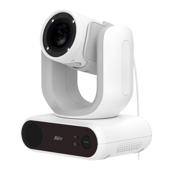
Product Introduction The MD330U Series PTZ Camera is a medical grade split-type camera designed with a removable Camera Head. Two models are provided: MD330U (Fill Light) and MD330UI (Night Vision). The MD330U features a Snapshot button and a Fill Light button on the left side of the Camera Head, while MD330UI only features a Snapshot button for users to capture snapshot images. -
Page 12: Led Indicators
LED Indicators The table below describes the two LED indicators on the front panel of the Camera Body: Split mode and Standalone mode LED LED Status Descriptions Camera initial process. Flash Orange Standby mode. Solid Orange Normal operation in Standalone mode. Solid Blue Privacy mode. -
Page 13: Dimensions
Dimensions 132.75mm 154mm 68mm MODE 168mm 126mm... -
Page 14: Mode Switch
Mode Switch The Mode button can be used when you want to remove the Camera Head to take a snapshot or place back the Camera Head. Install Camera Head Remove Camera Head Camera Head Camera Head Holder MODE MODE To remove the Camera Head: 1. -
Page 15: Precautions For Use
Installation Standalone Installation You can place the camera on a desktop or use the supplied screws to mount the camera to a flat surface. Place the camera unit flat on the desktop. Ensure the location is stable so that the unit will not be susceptible to shaking and/or falling. -
Page 16: Device Connection
Device Connection Connect to Camera Head Network Cable Power Adapter (not included) & Power Cord HDMI Cable USB Type-B to (not included) Type-A Cable RS-232 (VISCA) Router microSD Cable (not included) Card Power Outlet Joystick / Laptop TV / Monitor 1. - Page 17 3. USB Connection: Connect the camera to a desktop or laptop for video transmission when using other video conference software such as Skype or Teams. (Note 1) 4. Video Output Connection: Connect the camera to a TV or monitor to display video output. (Note 5.
-
Page 18: Remote Control
Remote Control The remote control requires two “AAA” batteries. Make sure batteries are installed properly before use. Name Function 1. Power Short press to turn on/off the Standby mode. 2. Home Move the camera to the Home position. HOME SNAP ... -
Page 19: Set Up The Camera
Set Up the Camera You can configure the camera settings using the OSD menu or the Web interface of the camera. OSD Menu To access the OSD menu, connect the camera to a monitor or TV using the HDMI cable, and then you can use the supplied Remote Control to operate the OSD Menu. -
Page 20: Dhcp
DHCP 1. Press the Menu button on the remote control to bring-up the OSD menu. 2. Select Network > DHCP > On. 3. Press to confirm setting. 4. After turning the DHCP on, you can go to System > Information to view the IP address. -
Page 21: Osd Menu Tree
OSD Menu Tree Layer Layer Layer Layer Exposure Value / Gain Limit Full Auto Level / Slow Shutter Exposure Value / Shutter Shutter Priority Speed / Gain Limit Level Exposure Mode Exposure Value / Iris Level / Iris Priority Gain Limit Level / Slow Shutter Iris Level / Shutter Speed / Manual... - Page 22 Layer Layer Layer Layer Frequency 50Hz / 59.94Hz / 60Hz 60Hz: 1080p/60, 1080p/30, 720p/60, 720p/30 Video 50Hz: 1080p/50, 1080p/25, Output Resolution 720p/50 59.94Hz: 1080p/59.94, 1080p/29.97, 720p/59.94 Audio Echo Cancel On / Off Off / NR / NR+BF / NR Noise Suppression Strong / NR DSP Audio Input Audio Beam Forming...
-
Page 23: Web Setup
Connect the camera from a remote site through the internet. Access the Web Interface of the Camera To access the Web interface of the camera, you have to find the IP address of the camera using AVer IPCam Utility or AVer PTZ Management software. - Page 24 5. Login with the new ID/Password, the Web interface of the camera will be displayed (Chrome browser). Please refer to the <Live View> chapter for more details. [Note] If IPCam utility cannot find the camera, please check following: 1. Please make sure the Ethernet connection of camera is well connected. 2.
-
Page 25: Accessing The Camera Via Aver Ptz Management
Accessing the Camera via AVer PTZ Management To find the IP address of your cameras using the AVer PTZ Management, follow the steps below. 1. Download the AVer PTZ Management software from https://www.aver.com/download-center 2. Download the Windows program and install it. -
Page 26: Live View
Live View You can control the camera and operate the Preset functions using this page. Camera Control Click the Camera Control tab to display the panel below for operation. Pan-Tilt-Zoom Control , and to navigate the camera view. Adjust the Pan Speed and Tilt Speed if necessary. -
Page 27: Preset
Focus Auto Focus ( ): Click for the camera to perform the auto focus. ): Click to manually adjust the focus. You can use the Focus + and Focus – Manual Focus ( buttons to adjust the focus. One Push Focus ( ): Click to automatically adjust the focus once. -
Page 28: Camera Settings
Camera Settings Exposure Click the Exposure tab to display the panel below for configuration. Exposure Mode: Options include Full Auto, Iris Priority, Shutter Priority and Manual. Select an exposure mode and optionally adjust the value of Exposure Value, Gain Level, Shutter Speed, Gain Limit Level, Iris Level, and BLC. -
Page 29: Image Process
Image Process Click the Image Process tab to display the panel below for configuration. White Balance: Options include AWB, ATW, Indoor, Outdoor, One Push and Manual. If Manual is selected, adjust the R Gain and B Gain manually. If One Push is selected, click the Set button in the One Push field when placing a white paper sheet in front of the camera lens. -
Page 30: Video & Audio
Video & Audio You can configure video and audio settings on this page. 【Video Setting】 Power Frequency: Select 50Hz, 59.94Hz or 60Hz based on your region. Video Output Resolution: Select a resolution to display on your video output device. 60Hz: 1080p/60, 1080p/30, 720p/60, 720p/30. -
Page 31: Network
Network You can configure network settings on this page. Hostname: The default Hostname is AVer. You can change the hostname to be displayed on other devices, e.g. IP router. DHCP: You can set up the network to DHCP or Static IP. -
Page 32: System
Camera Information: Displays the system information. Upgrade firmware: Follow below steps to upgrade the firmware. 1. Download the newest firmware from https://www.aver.com/download-center/ 2. On the Web page, go to System > Upgrade firmware. 3. Click Browse to select the firmware. - Page 33 Power Off to Preset: If this function is enabled, when power-off the camera, the camera will move to the input preset position. To set up this function, toggle the button on, input a preset position and then click Save. Ensure the preset positions have been pre-configured before enabling this function.
-
Page 34: Specification
Specification Camera Image Sensor 1/2.8" Exmor CMOS Effective Picture Elements 8 Megapixels 4K/30 (IP/UVC), 1080p/50, 1080p/30, 1080p/29.97, 1080p/25, Output Resolutions 1080i/60, 1080i/50, 720p/60, 720p/59.94, 720p/50 Minimum Illumination 0.7 lux (IRE50, F1.6, 30fps) ≥ 50dB S/N Ration Gain Auto, Manual Shutter Speed 1/1 to 1/10,000 sec Exposure Control Auto, Manual, Priority AE (Shutter, IRIS), BLC, WDR... - Page 35 General 100-240V AC~ to 12V DC 3.34A * The included Power Adapter (GSM40A12) is manufactured by Power Requirement MEAN WELL Enterprises Co., Ltd. with Class I classification. ** The power supply is specified as a part of ME EQUIPMENT. Power Input 12V DC Power Consumption Dimension (W x H x D)
-
Page 36: Troubleshooting
Troubleshooting This section provides useful tips on how to solve common problems while using this unit. There is no picture on the output screen. 1. Check all the connectors again as shown in this manual. 2. Verify the setting of the display output device. The picture on the output screen is distorted or the image is blurry. -
Page 37: Appendix
Appendix VISCA RS-232 Command Table Command Set Command Command Packet Comments 8x 01 04 00 02 FF CAM_Power Power ON/OFF 8x 01 04 00 03 FF Stop 8x 01 04 07 00 FF Tele(Variable) 8x 01 04 07 2p FF p=0 (Low) to 7 (High) CAM_Zoom Wide(Variable) - Page 38 8x 01 04 0B 02 FF Iris Setting CAM_Iris Down 8x 01 04 0B 03 FF 8x 01 04 0C 02 FF Gain Setting CAM_Gain Down 8x 01 04 0C 03 FF 8x 01 04 0D 02 FF Bright Setting CAM_Bright Down 8x 01 04 0D 03 FF...
- Page 39 Freeze On 81 01 04 62 02 FF Freeze On Immediately Freeze Off 81 01 04 62 03 FF Freeze Off Immediately Freeze Preset Freeze On 81 01 04 62 22 FF Freeze On When Running Preset Preset Freeze Off 81 01 04 62 23 FF Freeze Off When Running Preset pp: 0x00 To 0xFF normal preset pp: 0x5F =>...
- Page 40 Command Inquiry Command Reply Packet Comments Packet y0 50 02 FF CAM_PowerInq 8x 09 04 00 FF y0 50 03 FF y0 50 00 FF Auto y0 50 01 FF In Door y0 50 02 FF Out Door CAM_WBModeInq 8x 09 04 35 FF y0 50 03 FF One Push WB y0 50 04 FF...
-
Page 41: Visca Over Ip Settings
VISCA over IP Settings... -
Page 42: Cgi Command
CGI Command CGI List for Video Transmission Parameter CGI item name Command Parameter Name Description value Get JPEG /snapshot 1280x720 jpg Get RTSP stream rtsp://ip/live_st1 CGI List for Audio Parameter CGI item name Command Parameter Name Description value Auto Echo Cancel /cgi-bin?Set= ado_echo_cancel,3,N 0 ~ 1... - Page 43 CGI List for Various Settings Parameter Parameter CGI item name Command Description Name value exposure value /cgi-bin?Set= img_expo_expo,3,N&(random) value 1 ~ 9 N : value saturation /cgi-bin?Set= img_saturation,3,N&(random) value 0 ~ 10 N : value contrast /cgi-bin?Set= img_contrast,3,N&(random) value 0 ~ 4 N : value GET(Basic Reboot...
Need help?
Do you have a question about the MD330U Series and is the answer not in the manual?
Questions and answers