Table of Contents
Advertisement
Quick Links
Advertisement
Table of Contents

Related Manuals for Iwatsu SS-540


Summary of Contents for Iwatsu SS-540
- Page 1 Instruction Manual Current Probe SS-540/SS-550...
- Page 2 Ⓒ2021 IWATSU ELECTRIC CO., LTD. All rights reserved....
-
Page 3: Table Of Contents
Contents Contents Introduction ··················································································· 1 Safety Precautions ······································································· 1 Note ································································································ 11 Checking packed materials ························································· 11 Components ·················································································· 11 Management of instrument ························································· 12 Repair and sending instrument to be repaired ························ 12 Cleaning of instrument ································································ 12 Chapter 1 Overview ······································································ 13 1.1 Summary ···········································································... - Page 4 Contents Chapter 3 Daily check and calibration······································· 32 3.1 Maintenance ······································································ 32 3.2 Periodic Calibration ··························································· 32 3.3 Inspection ·········································································· 33...
-
Page 5: Introduction
Introduction • Thank you for purchasing this instrument of IWATSU ELECTRIC CO., LTD. We hope that you will enjoy it for years to come. • Please read this manual carefully before attempting to use the instrument. Store the manual in a safe place so it can be referred to when necessary. - Page 6 • Unauthorized reproduction of the contents of this manual is strictly prohibited. • If you have any questions about this instrument, contact Iwatsu office or our sales distributors. Revision History • April 2021: 1st edition KMLA00291...
- Page 7 Continued use under these circumstances may result in electric shock or fire. Contact Iwatsu office or our sales distributors for repair. Do not attempt to repair this instrument yourself. • Turn off the power to the insulating target conductor to...
- Page 8 • Do not use this instrument if the unit case is damaged. This may result in electric shock. If the unit case is damaged, contact Iwatsu office or our sales distributors for repair. • Connect only the recommended power unit to this instrument.
- Page 9 • When handling power cords and sensor cables: This may result in fire, electric shock, or equipment damage. If the power cord is damaged, contact Iwatsu office or our sales distributors for repair. ⋅ Do not attempt to fabricate power cord and sensor cable.
- Page 10 • Do not use this instrument when it has failed. Using a failed main unit or, cable or AC adaptor may be a cause of an electric shock or fire. In the event of a failure, contact Iwatsu office or our sales distributors for repair.
- Page 11 Read this page to ensure proper safety. (to be continued) Cautions • Do not supply current that exceeds the maximum continuous input range. The values are derived from the rise in temperature caused when the unit heats up during measurement. Do not input the current that exceeds this.
- Page 12 Read this page to ensure proper safety. (to be continued) Cautions • Before moving this instrument, make sure that the power supply plug is disconnected from the power supply receptacle and that the sensor head, output terminal (BNC) cable and other external connection lines are removed.
- Page 13 Read this page to ensure proper safety. (to be continued) Cautions • For your safety, when this instrument is not used for a long time, remove the power plug of this instrument from the power supply receptacle. • Do leave this instrument dusty...
- Page 14 (for SS-540) or hard (for SS-550) case, and then pack the housed instrument in the packing material used at the time of purchase, or the packing material or better. This instrument may fail if a large vibration or impact is applied during transportation, possibly causing a fire.
-
Page 15: Note
Checking packed materials When receiving this instrument, check the packed materials while referring to the following “Components.” If there is a missing item or an item damaged during transportation, immediately contact Iwatsu office or our sales distributors. Components Main unit ………….. -
Page 16: Management Of Instrument
When disposing of it, request a recycling company to dispose of it in accordance with local laws or regulations. Repair and sending instrument to be repaired If a failure occurs, send the instrument to Iwatsu office or our sales distributors. When sending an instrument to be repaired, clearly write the... -
Page 17: Chapter 1 Overview
⋅ Easy current measurement ⋅ Broadband frequency bandwidth SS-550 : DC - 100MHz SS-540 : DC - 50MHz ⋅ Compact unit capable of measuring low current ⋅ Simple protection function from excessive input ⋅ Unique development by using thin film Hall element... -
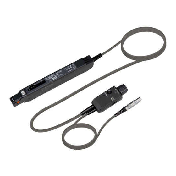
Page 18: Part Names
1.3 Part Names • External View 1.4 Part Functions ① Open-close lever Used to open and close the sensor head. Be sure to use this lever to open and close the sensor head. ② Sensor head Clamps the insulating target conductor to be measured and detects the current level. - Page 19 sudden violent changes in ambient temperature, mechanical stress, shocks and so on. ③ Demagnetizing switch (DEMAG) Used to eliminate magnetization from the magnetic core generated when the power is turned on and off or caused by excessive input. Be sure to do this before starting measurement.
-
Page 20: Specifications
1.5 Specifications 1.5.1 Instrument specifications Table1, Figure1 and Figure2 indicate SS-550 instrument specifications. Table2, Figure3 and Figure4 indicate SS-540 instrument specifications. The following values indicate unit performance 30 minutes after the power has been turned on in an ambient environment of 23°C ±... - Page 21 Table1. SS-550 Instrument specifications Frequency bandwidth DC to 100 MHz (−3 dB) Rise time 3.5 ns or less Waveform response Sag: 3 % or less (for 1kHz rectangular waveform) Overshoot: Within ±20 % (for the step waveform in rise time of 0.8 ns) Maximum continuous input 30 Arms (See Figure1 Derating by Frequency.) current range...
- Page 22 100k 100M Frequency [Hz] Figure 1. Derating by Frequency (SS-550) 100m 100k 100M Frequency [Hz] Figure 2. Input Impedance (SS-550, sample characteristics) Chapter 1 Overview...
- Page 23 Table2. SS-540 Instrument specifications Frequency bandwidth DC to 50 MHz (−3 dB) Rise time 7 ns or less Waveform response Sag: 3 % or less (for 1kHz rectangular waveform) Overshoot: Within +10 %/-20 % (for the step waveform in rise time of 3 ns) Maximum continuous input 30 Arms (See Figure3.
- Page 24 100k 100M Frequency [Hz] Figure 3. Derating by Frequency (SS-540) Figure 4. Input Impedance (SS-540, sample characteristics) Chapter 1 Overview...
-
Page 25: Certification Standards
Digital oscilloscope ViewGoII series that can attach DS-579, and power connector conversion cable are used together, and it is possible to use them slimly and compactly. If you have any questions about this instrument, contact Iwatsu office or our sales distributors. Chapter 1 Overview... -
Page 26: Chapter 2 Operation
Chapter 2 Operation 2.1 Preparations for Measurement 1. Prepare this instrument and the recommended power supply and oscilloscope or other waveform monitoring instrument. Note ⋅ This instrument output is terminated internally. It should be used with an oscilloscope whose input impedance is 1 MΩ or greater. -
Page 27: Demagnetizing And Zero Adjustment
2.2 Demagnetizing and Zero Adjustment Notes ⋅ Immediately after the power is turned on, this instrument will heat up, in some cases causing considerable offset voltage drift. This should stabilize almost completely in about thirty minutes. ⋅ When conducting continuous measurement, please note that the offset voltage will drift due to the ambient temperature, etc. - Page 28 Cautions • When removing the output connector, release the lock and then grasp the connector and pull to remove. Never try to forcibly remove the connector without first releasing the lock. Also, never pull the cable, as this may damage the terminator. •...
- Page 29 4. Without clamping this instrument to the insulating target conductor to be measured, press the open/close lever until the "UNLOCK" marking disappears. Then check to make sure that the sensor head is securely closed. 5. Press the DEMAG switch on the terminator. The process takes about one second.
-
Page 30: Measuring Methods
2.3 Measuring methods 1. Check to make sure that all safety requirements have been satisfied and all preparations for measurement (as described in the previous section) are complete. 2. Pull the open/close lever on the sensor unit to open the sensor head. - Page 31 600mA or less. Refer to Figure 5 (for SS-540) or Figure 6 (for SS-550). Current to be measured (A) Figure 5. Current consumption* vs. current to be measured (typical for SS-540) *The sum total of a positive and negative current consumption Current to be measured (A) Figure 6.
- Page 32 Cautions • The maximum continuous input range is determined by the temperature rise when this instrument heats up during measurement. Do not apply current that exceeds this range, as this may damage this instrument. • The maximum continuous input range will differ depending on the frequency of the measured current.
- Page 33 • In addition to the maximum continuous input range, there is a value listed under "During non-continuous input" in the Instrument Specifications: SS-550 / SS-540 Maximum continuous input range: 30 Arms During non-continuous input: 50 Apeak When using this instrument, make sure the effective value does not exceed the maximum continuous input range.
- Page 34 Note 1 ⋅ Do not place any unclamped conductor with an electric current of a frequency of 10 kHz or more near the sensor head. Current flowing in the conductor nearby may heat up the sensor head and cause its temperature to rise, leading to damage to the sensor.
- Page 35 Note 2 ⋅ Resonance may be generated depending on the frequency of the current being measured. This will not affect measurement. ⋅ In some cases, the position of the insulating target conductor to be measured in the clamp window may affect measurement.
- Page 36 3.2 Periodic Calibration This instrument must be inspected and calibrated periodically to ensure that signals are measured correctly. For periodical calibration, contact Iwatsu office or our sales distributors. We recommend that this instrument is calibrated about once a year. Chapter 3 Daily check and calibration...
- Page 37 2. Set the oscilloscope input coupling to DC. 3. With the sensor head on the current probe completely closed, connect this instrument (SS-540 or SS-550) to the oscilloscope and press the DEMAG switch. Immediately after the switch is pressed, a sine wave of approximately 300 mVp-p will be output, gradually becoming attenuated and stopping after a few seconds.
- Page 38 Contact Us Overseas Sales Sect., Sales Dept. No.2 Address : 1-7-41 Kugayama, Suginami-ku, Tokyo 168-8501, Japan Phone : +81 3 5370 5483 Facsimile : +81 3 5370 5492 Web Site : http://www.iti.iwatsu.co.jp/index_e.html E-mail : info-tme@iwatsu.co.jp...
Need help?
Do you have a question about the SS-540 and is the answer not in the manual?
Questions and answers