Table of Contents
Advertisement
Quick Links
Advertisement
Table of Contents

Related Manuals for Iwatsu CS-200 Series


Summary of Contents for Iwatsu CS-200 Series
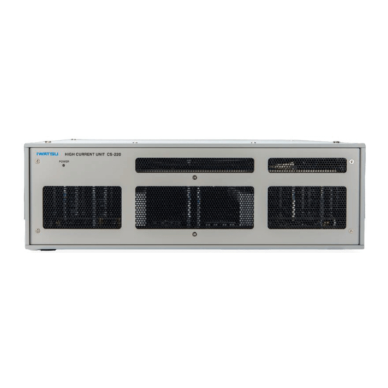
- Page 1 Manual HC UNIT CS-200 Series CS-205 / CS-210 / CS-220...
- Page 2 Copyright Ⓒ 2021 IWATSU ELECTRIC CO., LTD. All rights reserved....
- Page 3 Preface ◇Thank you for purchasing the HC Unit CS-200 Series. We sincerely hope to continue using our instruments for a long time. ◇Please read this manual carefully and understand its contents before using this instrument, and then keep this manual handy for future reference.
- Page 4 Continued use under these circumstances may result in electric shock or fire. After taking measures above, contact IWATSU or our sales distributors for repair. Repairing the instrument by yourself is very dangerous. Do not attempt to repair the instrument under any circumstances.
- Page 5 If any foreign object enters this instrument, after making the power switch a standby, and pulling out the power plug from the power outlet, contact IWATSU or our sales distributors for repair.
- Page 6 When performing inspection, calibration, or repair, contact IWATSU or our sales distributors. ● When handling power cord, observe items below: If not, fire or electric shock may occur. If the power cord is damaged, contact IWATSU or our sales distributors for repair.
- Page 7 Instrument, set the power switch to standby, remove the plug from the outlet, and then contact IWATSU or our sales distributors for repair. ● Do not use this instrument if it is not functioning cor- rectly.
- Page 8 Read this page to ensure proper safety. (Also read the following pages.) CAUTION ● Set the power supply cord up in the place where it is pulled out easily. When this instrument is a dicey situation, it is necessary to cut power off promptly. Do not attempt to place this instrument in the location where difficult to unplug the power supply cord from the receptacle.
- Page 9 If you do not have the proper packing material or shock absorbing material, contact IWATSU or our sales distributors. When having the intrument transported by a shipping company, write "Precision Instrument - Handle With Care" on each side of the packing box.
- Page 10 Long-term use of an instrument having a dirty or dusty interior may cause a fire or malfunction. It is recommended that you contact IWATSU or sales distributors to check and clean the interior, calibrate, etc., about once per year.
- Page 11 ....... : 1 Control interface cable (length: 1.0 m) ............: 1 Interlock/Sense cable (length: 1.0m) ............: 1 Contact Us IWATSU ELECTRIC CO., LTD. Overseas Sales Sect., Sales Dept. No.2, 7-41, Kugayama 1-Chome, Suginami-ku, Tokyo, 168-8501 Japan TEL: +81-3-5370-5483 FAX: +81-3-5370-5492 URL: https://www.iti.iwatsu.co.jp/index_e.html...
- Page 12 How to use this document; Notation It is recommended that the biginner of this instrument should use the instrument after reading this Instruction Manual carefully. ◆About the explanation method of each section The structure is as follows for items with many explanations such as functions, operations, and specifi- cations.
-
Page 13: Table Of Contents
Contents Chapter 1 Overview ............................1-1 1.1 Future ................................1-1 Chapter 2 Names and Functions ........................2-1 2.1 The Front panel of HC Unit .......................... 2-1 2.2 The Rear Panel of HC Unit ........................... 2-2 Chapter 3 Basic Operation ..........................3-1 3.1 Install the Instrument............................. - Page 14 MEMO...
-
Page 15: Chapter 1 Overview
CS-3000 Series and CS-5000 Series in order to evaluate power semiconductor devices in the power electronics market. The HC Unit CS-200 Series was developed as a large current unit for the Curve Tracer CS-8000 Series, and you can select and use a model that matches the current of the measurement range of the Curve Tracer specifications and connection options. - Page 16 For the Test Fixture in which the DUT to be measured is set, close the cover before measuring. HC UNIT CS-200 Series Instruction Manual...
-
Page 17: Chapter 2 Names And Functions
CONTROL INTERFACE IN connector on the rear. ・When the power of the CS-8000 Series is ON. The LED Lights blue The HC Unit CS-200 Series does not have an operation switch for turning the power on and off. ② Vent The outside air is sucked in through this vent and exhausted by the fan motor on the rear. -
Page 18: The Rear Panel Of Hc Unit
The connector for controlling each unit from the CS-8000 Series. It is used by connecting to the OUT side of the CONTROL INTERFACE connector of the CS-8000 Series or the CONTROL INTERFACE connector of other units. When using multiple units, connect them with a daisy chain. HC UNIT CS-200 Series Instruction Manual... - Page 19 LOW connector on the CS-322 Test Fixture. ⑩ HIGH CURRENT DRAIN/COLLECTOR HIGH Connector Use the included HC-FIXTURE Connection Unit to connect to the HIGH CURRENT DRAIN / COLLECTOR HIGH connector on the CS-322 Test Fixture. HC UNIT CS-200 Series Instruction Manual...
- Page 20 Chapter 2 Name and Functions MEMO HC UNIT CS-200 Series Instruction Manual...
-
Page 21: Chapter 3 Basic Operation
If there is a change in the environment, wait for a while until the environment inside the Instruments become accustomed to the surrounding environment. Turn on the main power switch of the CS-8000 Series. HC UNIT CS-200 Series Instruction Manual... -
Page 22: Connect The Power Cord
In addition, connect to the power outlet to which the power cord of CS-8000 Series or Test Fixture is connected and the power outlet as close as possible. AC LINE INPUT The Rear Panel of CS-210 Power Connector Power Cord Power Plug Power Outlet Figure 3.1 Connection of Power Cord (CS-210) HC UNIT CS-200 Series Instruction Manual... -
Page 23: Connection With Cs-8000 Series And Test Fixture Cs-322
Explains how to connect the Curve Tracer CS-8000 Series and Test Fixture CS-322 to the HC Unit CS-200 Series. As shown in Figures 3.2 and 3.3, place the Test Fixture CS-322 on the HC Unit CS-200 Series and fix it. Figure 3.2 Connection with Test Fixture (a) Figure 3.3 Connection with Test Fixture (b) - Page 24 Mandatory (OUT) Table 3.3 Cable connection table between CS-8000 Series and HC Unit CS-8000 Series Connector name Cables to use, etc. HC Unit No. Remark ④ ⑥ HC SENSE Interlock / sense Cable Mandatory HC UNIT CS-200 Series Instruction Manual...
- Page 25 Be careful not to let the cable on the rear get caught in other heavy objects. Not all of these wires are required, but connect them all until you are comfortable with the measurements. Figure 3.4 Cable connection diagram HC UNIT CS-200 Series Instruction Manual...
- Page 26 Chapter 3 Basic Operation Memo HC UNIT CS-200 Series Instruction Manual...
-
Page 27: Chapter 4 Daily Maintenance And Calibration
4.3 Repair and sending of repaired Instrument If a failure occurs, contact Iwatsu or our sales distributors. If an unexpected failure by our fault occurs during the warranty period, it can be repaired without charge. - Page 28 Chapter 4 Daily Mentenance and Calibration Memo HC UNIT CS-200 Series Instruction Manual...
-
Page 29: Chapter 5 Specifications
Note1: When the pulse width is narrow, it may not be possible to output up to the maximum voltage / current. ≦0.1% (2 kA) Duty Ratio ≦0.25% (1 kA) ≦0.5% (500 A, 200 A) ≦1% (100 A to 5 A) HC UNIT CS-200 Series Instruction Manual... - Page 30 Note: The performance is the ensured value after the warm-up time. Storage -20 °C to +60 °C, 5% to 80% RH (No condensation) Temperature/Humidity Altitude Operating: Up to 2000 m HC-FIXTURE Connection unit Accessory Instruction manual (this manual) Power Cord Cord Strap HC UNIT CS-200 Series Instruction Manual...
-
Page 31: Compliance Information
Chapter 5 Specifications 5.2 Compliance information Directive Descriptions EN 61010-1: 2010/A1: 2019 Low Voltage Directive (Safety) Pollution degree 2 Overvoltage category (installation category) II Directive EN 61326-1: 2013 (Group1,ClassA) RoHS Directive EN IEC 63000: 2018 HC UNIT CS-200 Series Instruction Manual... -
Page 32: External Dimensions
Chapter 5 Specifications 5.3 External dimensions Unit: mm Tolerance ± 3 Figure 5.1 CS-220 Unit: mm Tolerance ± 3 Figure 5.2 CS-210 / CS-205 HC UNIT CS-200 Series Instruction Manual... - Page 34 CS-205 / CS-210 / CS-220...
Need help?
Do you have a question about the CS-200 Series and is the answer not in the manual?
Questions and answers