
Related Manuals for Setra Systems 567


Summary of Contents for Setra Systems 567
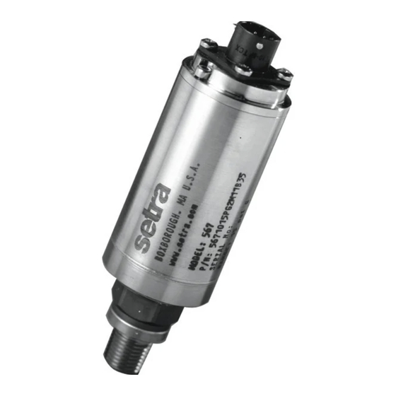
- Page 1 Installation Guide MODEL 567 Pressure Measuring Transducers 1-800-257-3872 TOLL FREE 1-978-264-0292 FAX www.Setra.com Web Site 560550-0093 Rev A...
- Page 2 Setra offers a complete line of products for these industries: Industrial HVAC Test & Measurement Barometric Ultra High Purity / Sanitary...
-
Page 3: Hazardous Products
Mark on the unit does not relate to the Pressure Equipment Directive. INTRODUCTION Series 567 are fluid pressure measuring transducers in which a four active arm Wheatstone bridge of thin film CVD gauges, integral with a beam structure connected to a pressure summing diaphragm, is used to convert fluid pressures into a proportional electrical signal. -
Page 4: Mechanical Installation
To fit, use a 22.2 mm (7/8 inch) AF wrench on the hexagon provided and apply maximum torque of 11.65 lbf-ft (15.8Nm). The Customer must ensure that the pressure seal is suitable for the application. If in doubt contact Setra Systems. Vibration: Where present, mount in a saddle clamp such as part number GA19 (material: Polypropylene). -
Page 5: Operation
APPROVED CABLES Setra Systems uses cable comprising 7 color-coded wires, with a central vent tube, enclosed by an aluminium/polyester shield where the shield is in contact with a separate drain wire. The outer shield material is Polyurethane (immersible, +70°C). Other shield materials available on request for harsh environments. -
Page 6: Load Resistance
ADJUSTMENT OF ZERO AND SPAN CONTROLS Switch and potentiometers provide continuous adjustment over the range 120% to 17% of nominal pressure range. Zero and Span controls are precisely set during manufacture and should only need adjustment if there is a change in the required pressure measurement. Access to these controls is provided by means of a removable end plate. -
Page 7: Supply Voltage
FIGURE 1 SUPPLY VOLTAGE Non I.S: 8.5 to 40V d.c. I.S: 8.5V to 28V d.c. MAINTENANCE Routine Inspection: Not required except for periodic inspection of the cable to ensure that these are neither damaged nor softened by incompatible liquid. DO NOT use high voltage insulation testers or any device which generates more than 50V d.c. for this test. -
Page 8: Electrical Connection
SERVICING The transducer cannot be repaired locally and if damaged should be returned to Setra Systems with the following: Name and phone number of person to contact Shipping and billing information Full description of malfunction Remove any pressure fittings and plumbing that you may have installed and enclose any required mating electrical connectors and wiring diagrams.
Need help?
Do you have a question about the 567 and is the answer not in the manual?
Questions and answers