
Related Manuals for Setra Systems 540 Series


Summary of Contents for Setra Systems 540 Series
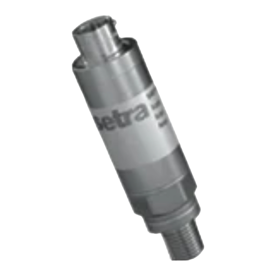
- Page 1 Installation Guide MODELS 540 / 541 / 542 Pressure Measuring Transducers 1-800-257-3872 TOLL FREE 1-978-264-0292 FAX www.Setra.com Web Site 560550-0085 Rev A...
- Page 2 Setra offers a complete line of products for these industries: Industrial HVAC Test & Measurement Barometric Ultra High Purity / Sanitary...
-
Page 3: Hazardous Products
Please Note: Series 540 / 541 / 542 are designed and manufactured in accordance with sound engineering practice as defined by the Pressure Equipment Directive 97/23/EC. This product must not be used as a “safety accessory” as defined by the Pressure Equipment Directive, Article 1, Paragraph 2.1.3. -
Page 4: Mechanical Installation
To fit, use a 7/8 inch AF (22.2mm) wrench on the hexagon provided and apply maximum torque of 20 lbf-ft (27Nm). The Customer must ensure that the pressure seal is suitable for the application. If in doubt contact Setra Systems. Vibration: Where present, mount in a saddle clamp such as part number GA17 (material: Polypropylene) or GA20 (material: Polyamide). -
Page 5: Electrical Installation
6 pin receptacle. The mating socket (not supplied) must conform to MIL-C-00264872. APPROVED CABLES Setra Systems uses cable comprising 6 color-coded wires, with a central vent tube, enclosed by an aluminium/polyester shield where the screen is in intimate contact with a separate drain wire. The outer sheath can be of various material, depending upon application and operating temperature, e.g. -
Page 6: Operational Life
Compensated Temperature Range Model Electrical Connector Temperature 540 / 542 10-6 Bayonet Connector -65°F to +250°F (-54°C to +120°C) 10-6 Bayonet Connector -65°F to +390°F (-54°C to +200°C) 540 / 542 Weatherproof Cable -65°F to +250°F (-54°C to +120°C) 540 / 542 Molded Immersible Cable -65°F to +250°F (-54°C to +120°C) 10-5 Screw Lock Connector... -
Page 7: Maintenance
MAINTENANCE Routine Inspection: Not required except for periodic inspection of the cable and molding to ensure that these are neither damaged nor softened by incompatible liquid. If Malfunction Occurs: Isolate the free end of the cable and measure the input and output resistance. -
Page 8: Warranty
Remove any pressure fitting and plumbing that you may have installed and enclose any required mating electrical connectors and wiring diagrams. Please ship to Setra Systems at the address shown below or to your local Setra Distributor when a replacement/repair is required. -
Page 9: Electrical Requirements
W A R N I N G * IF INSTRUMENT IS SUBJECTED TO +400°C PLUS Some instruments use Viton sealant. Above +400°C this material decomposes producing (amongst others) Hydrofluoric Acid which is extremely corrosive * DO NOT ALLOW CONTACT WITH SKIN If it is suspected that an instrument has been subjected to temperatures in excess of +400°C CONTACT OUR SALES OR SERVICE DEPARTMENT TO...
Need help?
Do you have a question about the 540 Series and is the answer not in the manual?
Questions and answers