
Subscribe to Our Youtube Channel
Related Manuals for Alfa Laval ALP 100


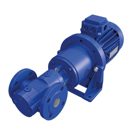
Summary of Contents for Alfa Laval ALP 100
- Page 1 Component Description Screw pumps - ALP series Sizes 100 - 280 Magnetic coupling Product No. OIA 04en Printed: 05/2015 Book No: 9008785-02 Operating Instructions...
- Page 2 Alfa Laval reserve the right to make changes at any time without prior notice. Any comments regarding possible errors and omissions or suggestions for improvement of this publication would be gratefully appreciated. Copies of this publication can be ordered from your local Alfa Laval company.
-
Page 3: Table Of Contents
Contents Warning signs in text Warning signs About this document General information Target groups Symbols Associated documents Safety Proper use Safety information Safety instructions for magnetic coupling systems. Labelling Type code Communication plate Technical data Operating limits Required NPSH values Weights Dimensions Capacity tables... - Page 4 Transportation, Storage and Disposal Unpacking and checking the state of delivery 25 Lifting the pump/pump unit Storage Preservation 7.4.1 Removing the preservation 7.4.2 Disposing of the pump Installation, removal and connection Safety instruction on installation, removal and connection Installation Installing the pump Protect the pump against soiling 8.4.1 Connecting the pump to the pipe system...
- Page 5 10.6 Installing the magnetic coupling 10.6.1 Mounting the inner rotor 10.6.2 Mounting the outer rotor 10.7 Replacing the ball bearing 10.7.1 Removing the ball bearing 10.7.2 Installing the ball bearing Troubleshooting 11.1 Possible faults 11.2 Troubleshooting 12 Appendix 12.1 General drawings 12.2 Parts table 12.3 Tightening torques 12.4 Required tool for maintenance work EC Declaration of conformity...
- Page 7 Study instruction manuals and observe the warnings before installation, operation, Service and maintenance. Not following the instructions can result in serious accidents. In order to make the information clear only foreseeable conditions have been considered. No warnings are given, therefore, for situations arising from the unintended usage of the machine and its tools.
-
Page 9: Warning Signs In Text
Warning signs in text Warning signs Pay attention to the safety instructions in this manual. Below are definitions of the three grades of warning signs used in the text where there is a risk for injury to personnel. DANGER indicates an imminently hazardous situation which, if not avoided, will result in death or serious injury. - Page 10 1 Warning signs in text 1.1 Warning signs...
-
Page 11: About This Document
About this document General information The operating instructions form part of the pump or of the pump unit and must be kept for future reference. Further more please observe associated documents. Target groups Target group Tasks ● Keep these instructions available at the system site for future Operator-owner reference. - Page 12 2 About this document 2.1 General information...
-
Page 13: Safety
Safety Proper use ● Use the pump solely for transporting lubricating liquids that are chemically neutral and that contain no gas or solid components. ● Use the pump only within the performance limitations specified on the rating plate and in the “Technical data”... -
Page 14: Safety Instructions For Magnetic Coupling Systems
3 Safety 3.3 Safety instructions for magnetic coupling systems ● In case of systems with an increased potential of danger to humans and/or machines the failure of a pump may not lead to injuries or damage to property. − Always equip systems with an increased potential of danger with alarm equipment. -
Page 15: Labelling
Labelling Type code 1 Model 2 Size ALP-0115-DAA100 3 Seal type 4 Overflow valve 5 Completion 6 Motor size Figure 1 Type code Item Designation Type Model ALP: Single pump Size Corresponds to flow rate in [l/min] at 1450 min Mechanical seal of hard material Seal type Magnetic coupling... -
Page 16: Communication Plate
4.2 Communication plate 4 Labelling Communication plate 1 Pump type 2 Serial number 3 Year of construction 4 Item number 5 Temperature max. 6 Differential pressure max. Figure 2 Rating plate... -
Page 17: Technical Data
Technical data Operating limits Size 100 - 280 Overflow valve A Overflow valve B Differential pressure max. [bar] End pressure max. [bar] Valve opening pressure [bar] 6 ± 10 % 10 ± 10 % Temperature max. [°C] Temperature min. [°C] for pump materials 1.4 - 10000 1.4 - 10000 Viscosity min. -
Page 18: Weights
5 Technical data 5.2 Required NPSH values NPSH value [mWC] at NPSH value [mWC] at Viscosity Viscosity Size Size Rotation speed [min Rotation speed [min 1450 1750 2900 3500 1450 1750 2900 3500 11.4 Table 2 Required NPSH values Weights Size Motor Magnet... -
Page 19: Dimensions
5 Technical data 5.3 Weights Dimensions Size Pump [mm] Shaft end [mm] D3 S1 B1 B2 100 - 115 272.5 160 138 43 - 165 - 215 333.5 230 200 110 14 122.5 20 47 - 230 - 280 63.5 18 178.5 363.5 230 200 110 14 47 -... - Page 20 5 Technical data 5.4 Dimensions S1/Z1 Figure 1 Dimensional drawing of ALP pump and pump unit.
-
Page 21: Capacity Tables
5 Technical data 5.5 Capacity tables Capacity tables Capacity at 50 Hz, Δp = 4 bar Rotat- max* Delivery rate [l/min] at viscosity [mm Size speed [kW] 460** 700** 1200** [min 2800 174.5 178.7 180.0 181.5 183.0 184.3 185.5 185.7 186.2 186.6 1400 1600 80.5 84.7 85.9 87.4 88.9 90.2... -
Page 22: Noise Levels
5 Technical data 5.6 Sound pressure levels Rotat- max* Delivery rate [l/min] at viscosity [mm Size speed [kW] 460** 700** 1200** [min 3400 214.8 219.0 220.3 221.8 223.3 224.6 225.8 226.0 226.5 226.9 1700 1220 100.6 104.8 106.1 107.6 109.1 110.4 111.6 111.8 112.3 112.7 1100... -
Page 23: Function Description
Function description Structure Figure 1 Structure of ALP pump Figure 2 Structure of ALP pump with magnetic coupling and motor Overflow valve Balancing cylinder Pump Coupling hub Screw plug Ball bearing Pump bracket Outer rotor Idle screw Main screw Motor Inner rotor End cover Pump housing... -
Page 24: Standard Direction Of Rotation
6.2 Magnetic coupling 6 Function description Axial support of the main screw is carried out by a deep-groove ball bearing. An internal overflow valve protects against excessive pressure that could cause housing parts to burst. 6.1.1 Standard direction of rotation: Clockwise, as seen from the drive;... -
Page 25: Transportation, Storage And Disposal
Transportation, Storage and Disposal Unpacking and checking the state of delivery 1. Upon delivery unpack the pump/pump unit and check for transport damage. 2. Report any transport damage immediately to the manufacturer. 3. Dispose of packing materials in accordance with the locally applicable regulations. Lifting the pump/pump unit Figure 1 Attachment of hoisting equipment - schematic diagrams. -
Page 26: Storage
7.3 Storage 7 Transportation, Storage and Disposal Risk of injury and/or damage to equipment should the pump/pump unit fall. ● Use intact and correctly dimensioned hoisting equipment suitable for the weight to be lifted. ● Choose the attachment points of the hoisting equipment according to the centre of gravity and weight distribution. -
Page 27: Removing The Preservation
7 Transportation, Storage and Disposal 7.4 Preservation ● For delivery with long-term preservation: If the packaging has been opened or damaged. Preserving the internal surfaces of the pump 1. Close the suction connection of the pump with a blind flange. 2. -
Page 28: Disposing Of The Pump
7.4 Preservation 7 Transportation, Storage and Disposal Risk of injury through emitted preservative oil. ● Wear protective clothing during all the work. ● Remove the blind flange with caution to relieve any pressure inside the pump. ● Collect the emitted oil safely and dispose of it in an environmentally compatible manner. - Page 29 7 Transportation, Storage and Disposal 7.4 Preservation 1. Disassemble the pump. 2. Clean residues of the pumped liquid from the individual parts. 3. Separate sealing elements made of elastomers and ceramics (SiC) from the pump and dispose of them in the residual waste. 4.
- Page 30 7.4 Preservation 8 Installation removal and connection...
-
Page 31: Installation, Removal And Connection
Installation, removal and connection Safety instruction on installation, removal and connection The following safety instruction must be observed during installation, removal and connection work. ● There is a risk of death for people with pacemakers. − Under no circumstances may persons with pacemakers perform installation, removal or connection work. - Page 32 8.3 Installing the pump 8 Installation removal and connection Figure 1 Model ALP vertical mounting Figure 2 Model ALP horizontal mounting Prerequisite: ● The pump connections are to be protected against soiling, for example by using the protective covers mounted in the factory Leaking pumped liquid can damage the motor.
-
Page 33: Protect The Pump Against Soiling
8 Installation removal and connection 8.4 Protect the pump against soling Protect the pump against soiling Damage through impurities in the pipe system. ● During welding work attach protective covers to the connecting flanges. ● Ensure when welding that welding beads and abrasive dust cannot get into the pipe system and the pump. -
Page 34: Connecting The Motor
8.4 Protect the pump against soling 8 Installation removal and connection 1. Turn the pump shaft or the fan impeller of the motor. This tests that the pump runs smoothly. If the pump cannot be turned by hand, remedy the fault before installing the pump, see paragraph 11 ‘‘Troubleshooting”. -
Page 35: Removing The Pump
8 Installation removal and connection 8.5 Removing the pump Removing the pump Aids: ■ Vessels for leaking pumped liquid Risk of death resulting from electric shock. ● Ensure that the power supply is disconnected. ● The motor may only be separated from the power supply by an authorized electrician. - Page 36 8.5 Removing the pump 8 Installation removal and connection...
-
Page 37: Operation
Operation Commissioning The following safety instruction must be observed during commissioning: ● There is a risk of death for people with pacemakers. − Under no circumstances may persons with pacemakers perform commissioning work. The following instructions must always be observed: ●... -
Page 38: Filling The Pump
9.3 Filling the pump 9 Operation ● Calculate the flow resistance and determine the remaining pump intake. ● Monitor the suction-side pressure. ● Check and clean the commissioning filter regularly. ● Recommended rinsing duration with commissioning filter: 50 -100 hours Filling the pump There are 2 possible ways to fill the pump: ●... -
Page 39: Checking Direction Of Rotation
9 Operation 9.5 Checking direction of rotation 1. Open the vent hole 3 so that the air can escape during the filling process. 2. Open the suction or pressure-side shut-off device and fill the pump via the suction or pressure connection until pumped liquid is emitted at the vent hole. -
Page 40: Commissioning The Pump
9.6 Commissioning the pump 9 Operation Dry running can damage pump equipment. ● Ensure that the pump is filled properly. ● Switch the pump on for a maximum of 1 second and then off again immediately. 1. Switch on the power supply and then turn it off again immediately. -
Page 41: Taking Pump Out Of Operation
9 Operation 9.7 Taking pump out of operation Dry running can damage pump equipment. ● Ensure that the pump is filled properly. ● If the pump does not deliver after 10 - 15 seconds, abort commissioning. 1. Ensure that the pump is filled. In case of doubt pre-lubricate the pump by pouring in liquid via the vent hole, see paragraph 9.3 ‘‘Filling the... -
Page 42: Recommissioning The Pump
9.8 Recommissioning the pump 9 Operation ● Carry out the following measures during shutdowns: Pump is Measure − Depending on the pumped liquid, see Table. 2, below. ● Shut down for longer period ● Drained − Close the pressure-side and suction-side stopcocks. −... -
Page 43: Maintenance
10 Maintenance 10.1 Safety instructions on maintenance & repairs The following safety instructions must be observed during all work: ● There is a risk of death for people with pacemakers. − Under no circumstances may persons with pacemakers perform maintenance or repair work. −... -
Page 44: Magnetic Coupling
10.3 Magnetic coupling 10 Maintenance Finding Cause Remedy Increased running noises. Incipient damage to bearing. Replace the bearing. Reduction in the flow rate Advanced wear of screws and Replace the pump. or pressure under constant housing. operating conditions. Table 1 Check table for required maintenance 1. -
Page 45: Replacing The Magnetic Coupling
10 Maintenance 10.5 Replacing the magnetic coupling 10.5 Replacing the magnetic coupling ● Removing the magnetic coupling 10.5.1 Dismantling the outer rotor 914.5 914.3 Figure 1 Figure 2 Figure 3 Pump Outer rotor 914.3 Socket screw Coupling hub Motor 914.5 Socket screw Pump bracket Threaded pin Mounting lever... -
Page 46: Dismantling The Inner Rotor
10.5 Replacing the magnetic coupling 10 Maintenance 1. Before dismantling close the suction and pressure connection of the pump with protective covers. 2. Loosen the connecting screws 914.3 between the motor 529 and pump bracket 180 and lift the pump with pump bracket from the motor, see paragraph 10.5.1 “Dismantling the outer rotor’’... -
Page 47: Installing The Magnetic Coupling
10 Maintenance 10.6 Installing the magnetic coupling 1. Loosen the socket screws 914.2 between the pump and pump bracket 180 and remove the pump bracket. 2. Loosen the socket screws 914.6 between the containment can 038 and pump, paragraph 10.5.2 ‘‘Dismantling the inner rotor’’... - Page 48 10.6 Installing the magnetic coupling 10 Maintenance 1. Carefully clean the sealing surfaces. Clean and slightly grease the O-ring. Insert the O-ring 739.2 and slide the distance sleeve 040 onto the pump shaft, see paragraph 10.6.1 “Mounting the inner rotor’’ Figure 7. 2.
-
Page 49: Mounting The Outer Rotor
10 Maintenance 10.6 Installing the magnetic coupling 10.6.2 Mounting the outer rotor 914.5 Figure 10 914.3 Figure 11 Figure 12 Pump Outer rotor 914.5 Socket screw Coupling hub Motor 914.3 Socket screw Pump bracket Threaded pin 1. Carefully clean the outer rotor 515 with compressed air. -
Page 50: Replacing The Ball Bearing
10.7 Replacing the ball bearing 10 Maintenance 3. Place the coupling hub with outer rotor onto the shaft of the motor, see paragraph 10.6.2 “Mounting the outer rotor’’ Figure 10. Heating up to approx. 80 °C facilitates mounting. Tighten the threaded pin 884. 4. -
Page 51: Installing The Ball Bearing
10 Maintenance 10.7 Replacing the ball bearing Aids: ■ Disassembly tool, paragraph 12.4 “Required tool for maintenance work” ■ Open-end wrench ■ Extractor 1. Remove the circlip 472 and screw plug 165.1, see paragraph 10.7.1 “Removing the ball bearing” Figure 2. - Page 52 10.7 Replacing the ball bearing 10 Maintenance 1. Clean the fitting surfaces and the main screw. Grease the main screw slightly. 2. Push the supporting ring 868* onto the main screw, press the ball bearing 817 onto the main screw, see paragraph 10.7.2 ‘‘Installing the ball bearing’’...
-
Page 53: Troubleshooting
11 Troubleshooting 11.1 Possible faults Faults can have different causes. The following tables list the symptoms of a fault, the possible causes and measures for elimination. Fault Cause/Remedy ● No pump suction 1, 2, 3, 4, 5, 6, 7, 8, 28 ●... - Page 54 11.2 Troubleshooting 11 Troubleshooting Cause Remedy − Clean the filter/strainer. Dirty filter/strainer Pump intake capacity reduced − Fill pump with liquid. by inadequate wetting − Carry out the electrical connection so that the Incorrect pump direction of rotation direction of pump rotation matches that of the arrow on the flange cover.
- Page 55 11 Troubleshooting 11.2 Troubleshooting Cause Remedy Lack of lubrication or foreign bodies have − Check the screw set and the housing. If caused superficial damage to rotating necessary, replace pump with free shaft end. pump components − Check the maximum operating temperature. Thermal or chemical loading of elastomer −...
- Page 56 11.2 Troubleshooting 11 Troubleshooting...
-
Page 57: Appendix
12 Appendix 12.1 General drawings 165.2 165.1 914.1 471.2 868* 471.1 Figure 1 ALP 100 - 280 914.5 914.3 914.2 914.4 914.6 040 739.2 Figure 2 Completion magnetic coupling ALP 100 - 280... -
Page 58: Parts Table
12.2 Parts table 12 Appendix 12.2 Parts table Pos.no. Denomination Pos.no. Denomination Pump Outer rotor Containment can Inner rotor Distance sleeve Pump bracket foot Balancing cylinder Motor Coupling hub Tensioning element Supporting ring 661** Screw set End cover 739.2 O-ring Pump housing Ball bearing 165.1... -
Page 59: Required Tool For Maintenance Work
12 Appendix 12.4 Required tool for maintenance work Tightening torque [Nm] for screws with metric threads + head with thread measured contact surfaces in inches + wedge lock Stainless steel Screw plugs with washers screws A2 and A4 elastomer seal 8.8 + Thread 10.9 Alu* Rust-proof Property Property Galvanized + Thread A4-70 class 70 class 80... -
Page 60: Ec Declaration Of Conformity
EC Declaration of conformity 12 Appendix 1 EC Declaration of Conformity EC Declaration of conformity X027551A The designating company Alfa Laval Kolding A/S Company name Albuen 31, DK–6000 Kolding, Denmark Address +45 79 32 22 00 Phone No. hereby declares that... -
Page 61: Notes
12 Appendix Notes Notes... -
Page 62: Notes
Notes 12 Appendix Notes...
Need help?
Do you have a question about the ALP 100 and is the answer not in the manual?
Questions and answers