Table of Contents
Advertisement
Instruction Manual
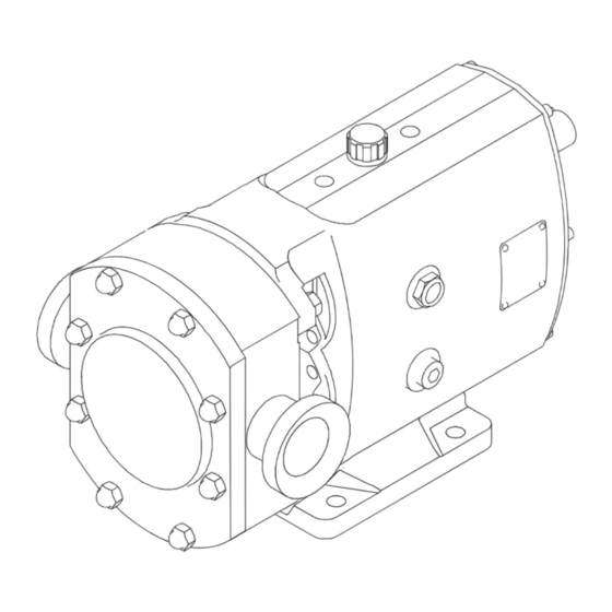
ATEX Addendum to SRU Instruction Manual - Rotary Lobe Pump - SRU Range
IMPORTANT!
When ordering spare parts please quote Pump Serial No.
Read all of this pump manual and any instructions supplied for ancillary equipment before the unit is installed,
operated or maintained.
ESE02195-EN9
Original manual
2020-02
Advertisement
Table of Contents

Related Manuals for Alfa Laval SRU Series


Summary of Contents for Alfa Laval SRU Series
- Page 1 Instruction Manual ATEX Addendum to SRU Instruction Manual - Rotary Lobe Pump - SRU Range IMPORTANT! When ordering spare parts please quote Pump Serial No. Read all of this pump manual and any instructions supplied for ancillary equipment before the unit is installed, operated or maintained.
-
Page 3: Table Of Contents
Table of contents The information herein is correct at the time of issue but may be subject to change without prior notice 1. EC Declaration of Conformity ............... 1.1. ATEX Directive 2014/34/EU ..............1.2. ATEX marking ..................2. Safety ....................2.1. -
Page 4: Ec Declaration Of Conformity
The person authorized to compile the technical file is the signer of this document Global Product Quality Manager Pumps, Valves, Fittings and Tank Equipment Lars Kruse Andersen Signature Title Name Alfa Laval Kolding, Albuen 31, DK 6000 Kolding 2020-02-11 Place Date (This Declaration of Conformity replaces Declaration of Conformity dated 2018-06-01) -
Page 5: Atex Directive 2014/34/Eu
In addition to the standard pump nameplate, ATEX Certified units have an additional ATEX name plate affixed to the pump gearbox housing stating the unit ATEX certification standard. Name plate example: Manufacturer Alfa Laval Eastbourne Ltd. BN23 6PQ, UK Pump Type SRU4 / 055 / LS Year Serial No. -
Page 6: Safety
2 Safety Unsafe practices and other important information are emphasized in this manual. Warnings are emphasized by means of special signs, see description in Standard Instruction Manual section 2.1 Special Conditions for Safe Use and 2.2 General Information. Always read the manual before using the pump! 2.1 Special conditions for safe use - Ensure checks and running conditions for the pump unit during operation to be according to section 4 Operation - Never operate pump outside max duty conditions specified in section 6.3 Seal Operation Data. -
Page 7: Installation
3 Installation 3.1 Installation Pumps and motorized pump units - Always follow the Installation instructions in the Standard Instruction Manual in conjunction with this addendum - Always ensure that instructions for all ATEX compliant equipment and components are followed (motors, couplings, reduction gears etc.) - Always make sure that pump gearbox, base plate and motor are electrically earthed - Always read section 4 Operation before pump start up... -
Page 8: Operation
4 Operation 4.1 Operation Pump units - Always read the operations instructions in the Standard Instruction Manual - Always read “Technical information” for shaft seals in section 6.1 6 Technical data - Always vent and purge the seal cavities and flush housing (if applied) of air/gas prior to start-up to avoid any dry-running. - Always make a visual inspection of the pump unit at startup to ensure there are no malfunctions e.g. -
Page 9: Daily Checks
4 Operation 4.3 Daily Checks Shaft seals, all types: - Ensure there is no unacceptable leakage. Shaft seals fitted with optional thermocouple: - Ensure proper function of signals, alarms and associated Ignition Prevention Systems related to the thermocouple. - Ensure for single seal, that the thermocouple reading is similar to the process media temperature (no more than 20°C above). -
Page 10: Maintenance
5 Maintenance 5.1 General Maintenance Guidelines - Always follow the Maintenance instructions in the Standard Instruction Manual - Always read “Technical information” section 6.1 Shaft Seals and section 6.3 Seal Operation Data - Always ensure that instructions of all ATEX compliant equipment and components are followed (motors, couplings, reduction gears etc.) - Always read section 4 Operation before starting up the pump unit after maintenance Pump Gearbox... -
Page 11: Mechanical Seals
5 Maintenance 5.3 Mechanical seals Mechanical seals should not be removed unless they are to be replaced. 5.3.1 R90 Single mechanical seal Refer to section 4.5.1 in Standard Instruction Manual 5.3.2 R90 Single mechanical seal with optional thermocouple Rotor Item Description Shaft Setting Dinemsion... - Page 12 5 Maintenance Seal fitting 1. Mark the shaft to indicate the seal setting length. 2. Lightly lubricate O-rings (71 and 73) with appropriate grease and fit to rotary and stationary seals (74 and 72). 3. If fitted replace abutment spacers. 4.
- Page 13 5 Maintenance Mechanical seals should not be removed unless they are to be replaced. 5.3.3 R90 Single flushed mechanical seal Refer to section 4.5.2 in Standard Instruction Manual 5.3.4 R90 Double flushed mechanical seal Refer to section 4.5.3 in Standard Instruction Manual 5.3.5 R90 Double flushed mechanical seal with optional thermocouple Item Description...
- Page 14 5 Maintenance Seal removal 1. Ensure the flush media is turned off and disconnect the flushing pipework. 2. Remove the rotorcase cover and rotors. 3. Turn the drive shaft until the drive ring grub screws (78) are visible through the flushing connections. 4.
-
Page 15: Heating/Cooling Devices
5 Maintenance 5.4 Heating/Cooling devices SRU pumps have the option of being fitted with jackets to the rotorcase cover and/or saddles to the rotorcase. These are primarily used for heating the pumphead so as to maintain the pumped media temperature. They may also be used for cooling purposes. -
Page 16: Thermocouple
5 Maintenance 5.5 Thermocouple Thermocouple Installation and Operation Thermocouples are fitted to the Pressure Relief Valve option and are offered as an option to monitor the mechanical seal temperature. The thermocouples supplied are Type-K. The thermocouple/s needs to be connected to a suitable Ignition Prevention System (IPS) conforming to Ignition Protection Level 1 (IPL1) as per the appropriate requirements of EN ISO80079-37:2016, Clause 7. -
Page 17: Atex Pressure Relief Valve
5 Maintenance 5.6 ATEX Pressure Relief Valve The below instructions replace those shown in the Installation Manual, pages 35 & 36. 3204-0007 Item Description Item Description Rotorcase cover Circlip Hydraulic piston Bush Valve guide O-ring, hydraulic piston Valve pin Valve pin Shim Spring Backstop disc... - Page 18 5 Maintenance 5.6.1 Relief Valve Disassembly 1. Unplug or disconnect the thermocouple lead connection (27). 2. Remove manual override lever if fitted. 3. Remove screws (25) and valve housing (24). 4. Remove notched nut(s) (23) and spring adjuster (21), If springs are still compressed when the notched nut reaches end of thread, release the spring adjuster screws (26).
- Page 19 5 Maintenance Pressure Relief Valve Operation The relief valve fitted to pumps certified for use in ATEX areas are fitted with a thermocouple used to measure the surface temperature of the front cover. During pump running, if the relief valve operates, the increased product slip (internal product recirculation) within the pump head can cause an increase in pumped product temperature and thereby allowing an uncontrolled increase in the pump head surface temperature beyond that allowed under the ATEX T-rating certified.
-
Page 20: Technical Data
6 Technical data 6.1 Shaft Seals The correct function of a mechanical seal is largely dependent upon its lubrication and cooling of the sealing surfaces. It is therefore extremely important to avoid any dry-running of the seal faces since this can cause excessive generation of heat and thus the possibility of exceeding the specified temperature class. -
Page 21: Monitoring Seal Face Temperature
6 Technical data 6.2 Monitoring Seal Face Temperature It must be ensured that the temperature of the seal face does not exceed the temperature class limit. This can be achieved by: A. Ensuring that the temperature measured locally at the seal face does not exceed the temperature listed in section 6.3 Seal Operation Data, e.g. -
Page 23: Seal Operation Data
6 Technical data 6.3 Seal Operation Data... - Page 24 © Alfa Laval Corporate AB This document and its contents is owned by Alfa Laval Corporate AB and protected by laws governing intellectual property and thereto related rights. It is the responsibility of the user of this document to comply with all applicable intellectual property laws. Without limiting any rights related to this document, no part of this document may be copied, reproduced or transmitted in any form or by any means (electronic, mechanical, photocopying, recording, or otherwise), or for any purpose, without the expressed permission of Alfa Laval Corporate AB.
Need help?
Do you have a question about the SRU Series and is the answer not in the manual?
Questions and answers