
Subscribe to Our Youtube Channel
Related Manuals for Alfa Laval ALP 15-85


Summary of Contents for Alfa Laval ALP 15-85
- Page 1 Component Description Oil Feed Pumps ALP 15-85 Product No. Jan 2020 Printed Book No. 9006009-02 V13 Marine & Diesel Equipment...
- Page 2 Telephone: +46 8 530 650 00 Telefax: +46 8 530 310 40 © Alfa Laval Tumba AB 01-2020 Original instruction This publication or any part there of may not be reproduced or transmitted by any process or means without prior written permission of...
-
Page 3: Table Of Contents
Contents EC Declaration of Conformity Warning signs in text Warning signs Function Description Application 3.1.1 Safety information Design 3.2.1 Mechanical seal 3.2.2 Direction of Rotation 3.2.3 Pressure relief valve Parts Fault Finding Possible faults Troubleshooting Maintenance Safety instructions on maintenance and repairs Required maintenance Mechanical seal... - Page 4 Weights Dimensions 6.4.1 Dimension drawing of ALP pump and pump unit Capacity tables 6.5.1 Capacity at 50 Hz, delta = 4 bar 6.5.2 Capacity at 60 Hz, delta = 4 bar 6.5.3 Noise levels 6.5.4 Labelling Installation Installing the pump Protect the pump against contamination Piping Strainer...
- Page 5 Study instruction manuals and observe the warnings before installation, operation, service and maintenance. Not following the instructions can result in serious accidents. In order to make the information clear only foreseeable conditions have been considered. No warnings are given, therefore, for situations arising from the unintended usage of the machine and its tools.
-
Page 7: Ec Declaration Of Conformity
1 EC Declaration of Conformity X027551A The designating company Alfa Laval Kolding A/S Company name Albuen 31, DK–6000 Kolding, Denmark Address +45 79 32 22 00 Phone No. hereby declares that Denomination: Three-Screw Pump Type: 2019-01-16 Date: Is in conformity with... - Page 8 1 EC Declaration of Conformity...
-
Page 9: Warning Signs In Text
2 Warning signs in text Warning signs Pay attention to the safety instructions in this manual. Below are definitions of the three grades of warning signs used in the text where there is a risk for injury to personnel. DANGER indicates an imminently hazardous situation which, if not avoided, will result in death or serious injury. - Page 10 2 Warning signs in text...
-
Page 11: Function Description
3 Function Description The operating instructions form part of the pump or of the pump unit and must be kept for future reference. Furthermore please observe the associated documents. Application Use the pump solely for transporting fuel or lubricating oils that are chemically neutral and that contain no gas or solid components. -
Page 12: Design
3 Function Description • Observe the valid national and international standards and specifications of the installation location. • In case of systems with an increased potential of danger to humans and/or machines the failure of a pump may not lead to injuries or damage to property. Always equip systems with an increased potential of danger with alarm equipment. -
Page 13: Direction Of Rotation
3 Function Description the differential pressure on the seal will always move some fluid through the gap which is filled by the film. Therefore a properly designed mechanical seal will always show a certain amount of leakage. The amount of leakage is depending on various factors, dominated by size, rotation speed and differential pressure. -
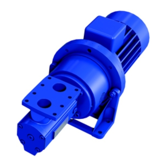
Page 14: Parts
3 Function Description Parts 1 Pressure relief valve 10 Mechanical seal 11 Pump 2 Screw plug 3 Idle screw 12 adapter housing 4 End cover 13 Motor 5 Sealing sleeve 14 adapter housing foot 6 Ball bearing 15 Motor-side coupling half 7 Main screw 16 Coupling intermediate ring 8 Pump housing... - Page 15 3 Function Description X027101A Fig. 1.Structure of ALP pump X027111A Fig. 2.Structure of ALP pump with elastomer coupling and motor...
- Page 16 3 Function Description Parts table Pos. no. Pos. no. Denomination Denomination Pump Circlip Spring 039*** Distance sleeve Sealing sleeve Coupling intermediate ring Coupling Pump bracket foot 056(*) Supporting ring Motor L-ring 661** Screw set O-ring End cover 739.1 Pump housing Ball bearing Screw plug Feather key...
- Page 17 3 Function Description 165.2 165.1 914.1 056* 739.1 X027151A Fig. 1.ALP 15–85 914.3 039*** 914.2 914.4 X027161B Fig. 2.Completion elastomer coupling ALP 15–85...
- Page 18 3 Function Description...
-
Page 19: Fault Finding
4 Fault Finding Possible faults Faults can have different causes. The following tables list the symptoms of a fault, the possible causes and measures for elimination. Cause/Remedy Fault No pump suction 1, 2, 3, 4, 5, 6, 7, 8, 30 Delivery rate too low 2, 3, 4, 9, 10, 11, 12, 13, 14, 15, 16 Pump runs noisily... - Page 20 4 Fault Finding Remedy No. Cause Incorrect pump direction of rotation Carry out the electrical connection so that the direction of pump rotation matches that of the arrow on the flange cover, see 7.6.3 Checking the direction of rotation on page 46 Differential pressure too high Check the system and reduce the differential pressure.
- Page 21 4 Fault Finding Remedy No. Cause 24 Thermal or chemical loading of Check the maximum operating temperature. elastomer seals exceeded Check the resistance of the elastomers with regard to the pumped liquid. 25 Cold start when delivering high-viscosity liquids Preheat the pumped liquid. 26 Foreign bodies in the pump Dismantle the pump and clean it.
- Page 22 4 Fault Finding...
-
Page 23: Maintenance
5 Maintenance Safety instructions on maintenance and repairs The following safety instructions must be observed during all the repair work: All the work may only be carried out by authorized qualified personnel. Wear protective clothing during all the work. Switch off the motor and secure it against being switched back on. -
Page 24: Required Maintenance
5 Maintenance Required maintenance The service life of the pump depends to a great extent on the operating conditions. If the operating limits are observed, see 6 Technical Data on page 33, the pump has a service life of many years. Signs of progressive wear of individual pump elements: Finding Cause... -
Page 25: Cleaning The Leakage Vent Hole
5 Maintenance Cleaning the leakage vent hole The regular small amounts of leakage can result in deposits that can prevent free draining of further leakage liquids after a longer operating period. The leakage vent hole must therefore be checked monthly and if necessary cleaned. Bearing damage due to insufficient drainage of shaft seal leakage X027171A... -
Page 26: Replacing The Elastomer Coupling
5 Maintenance Replacing the elastomer coupling Removing the coupling 052.2 052.1 914.2 914.3 Fig. 2 Fig. 3 X027181c Pump adapter housing 914.2 Socket screws 052.1 Pump-side coupling half 525 Coupling intermediate 914.3 Socket screws ring 052.2 Motor-side coupling half 529 Motor Risk of injury and/or damage to equipment should the pump/pump unit fall... - Page 27 5 Maintenance Loosen the connecting screws 914.2 between the pump 001 and adapter housing 180 and remove the adapter housing, see Fig. 3. Loosen the fixing screw on the pump-side coupling half 052.1 and remove the coupling half using suitable mounting levers.
- Page 28 5 Maintenance Mount the motor-side coupling half 052.2 on the shaft end of the motor, see Fig. 6. Heating the coupling to 80–100 °C facilitates mounting. 052.2 914.3 Fig. 6 X027221b Check the distance between the face of the coupling teeth and the connecting surface of motor flange.
-
Page 29: Replacing The Mechanical Seal And Ball Bearing
5 Maintenance Replacing the mechanical seal and ball bearing 5.7.1 Dismantling Aids: Disassembly tool, see 9.1.2 Required tools for maintenance work on page Open-end wrench Extractor Remove the circlip 472, screw plug 165.1 and feather key 866, see Fig. 7. X027231A Screw in the disassembly tool A by using the open-end wrench B, see Fig. - Page 30 5 Maintenance Pull the ball bearing 817 from the main screw using a suitable extractor C, see Fig. X027261A Remove L-ring 058, supporting ring 056*, sealing sleeve 043 along with o-ring 739.1 and stationary seal ring of the mechanical seal along with o-ring, see Fig. 11. 056* 739.1 Fig.
-
Page 31: Assembly
5 Maintenance 5.7.2 Assembly Aids: Clean the fitting surfaces and the main screw. Grease the main screw and o-rings slightly. First insert the L-ring 058 laterally into the sealing sleeve 043, then place the supporting ring 056* on the L-ring from above. - Page 32 5 Maintenance Press the ball bearing 817 onto the main screw, see Fig. 15. X027311A Mount the supporting ring 056 and circlip 471. Slide the main screw with premounted sealing sleeve into the pump housing until the main screw engages into the idle screws, see Fig.
-
Page 33: Technical Data
6 Technical Data Operating limits Design pressure max. [bar] Valve opening pressure [bar] 6 bar ± 10 %for separator systems 10 bar ± 10 % for fuel conditioning systems Temperature max. [°C] Temperature min. [°C] for pump materials Viscosity min. – max. [mm2/s] 1.4 –... -
Page 34: Weights
6 Technical Data The required NPSH values also need to be increased if there are gas contents, regardless of whether it is dissolved or not. In case of any doubt, please contact the manufacturer. Viscosity Viscosity Size NPSH value [mWC] at Size NPSH value [mWC] at [mm2/s]... -
Page 35: Dimensions
6 Technical Data Dimensions Dimensions ALP pump Pump Size Shaft end [mm] [mm] S1 Z1 15 – 20 73 128 103 80 14 30 30 – 40 73 135 103 80 14 30 55 – 85 83 160 125 100 11 19 35 21.5 6 Dimensions pump unit with elastomer coupling... -
Page 36: Dimension Drawing Of Alp Pump And Pump Unit
6 Technical Data 6.4.1 Dimension drawing of ALP pump and pump unit X027341A... -
Page 37: Capacity Tables
6 Technical Data Capacity tables 6.5.1 Capacity at 50 Hz, delta = 4 Q [l/hour] at viscosity [mm²/s] 50 Hz Motor kW 13 460** 700** ALP 15 0,75 1 625 1 678 1 693 1 712 1 731 1 747 1 762 1 765 1 771 0,55... -
Page 38: Capacity At 60 Hz, Delta = 4 Bar
6 Technical Data 6.5.2 Capacity at 60 Hz, delta = 4 Q [l/hour] at viscosity [mm²/s] 60 Hz Motor kW 13 460** 700** ALP 15 0,75 2 010 2 062 2 078 2 097 2 116 2 132 2 147 2 150 2 156 0,55... -
Page 39: Noise Levels
6 Technical Data 6.5.3 Noise levels Guide values at 1 m distance, 1450 min-1, 10 Sound pressure level max. ± 3 [dB(A)] Size 15 – 20 30 – 40 55 – 85 Pump 6.5.4 Labelling 6.5.4.1 Type code ALP-0020-BAC090 X027421A Pos. - Page 40 6 Technical Data...
-
Page 41: Installation
7 Installation Observe the following instructions: • When selecting the location take the operating limits, Net Positive Suction Head (NPSH) values and ambient conditions into account, see 6 Technical Data on page • The function, safety and service life may not be impaired by humidity, temperature influences or explosive atmospheres. -
Page 42: Protect The Pump Against Contamination
7 Installation X027351A Model ALP vertical mounting Model ALP horizontal mounting Protect the pump against contamination Avoid damage through impurities in the pipe system. During welding work attach protective covers in front of the connecting flanges. Ensure when welding that welding beads and abrasive dust cannot get into the pipe system and the pump. -
Page 43: Piping
7 Installation Piping The pipe installation must meet the following demands: • The pipes must be installed and supported with no support from the pump casing. • The pipe flanges must fit the pump flanges so that they can be connected without using any force. -
Page 44: Gauges
7 Installation Gauges Pressure gauges on both the suction and the pressure side must be connected by 1/2” sockets and ball valves. Commissioning 7.6.1 Cleaning the pipe system To protect the pump against soiling the complete pipe system has to be cleaned carefully before initial commissioning of the pump. - Page 45 7 Installation Open the shut-off valve on the pressure side of the pump. Vent the shaft seal compartment (3). In installations with positive suction pressure: After opening the inlet and outlet valves, simply open the deaeration plug (3) a few turns until oil sips out.
-
Page 46: Checking The Direction Of Rotation
7 Installation 7.6.3 Checking the direction of rotation The direction of rotation and the flow direction are indicated by arrows on the pump. The direction of rotation of the motor gives the direction of rotation of the pump. That is to say, the fan impeller of the motor must rotate in the direction in which the arrows on the pump are pointing to indicate direction of rotation. -
Page 47: Taking The Pump Out Of Operation
7 Installation If the pump does not deliver after 10–15 seconds of operation, abort initial commissioning, establish the cause of the fault and only then continue the commissioning procedure. Follow the instructions in the fault table, see Troubleshooting on page Run the pump for a few minutes to allow the pipe system to vent fully. -
Page 48: Recommissioning The Pump
7 Installation no corrosive burden remains liquid Drain the pump. — Preserve the pump. corrosive burden Measures depending on behavior of the pumped liquid • Drain the pump via the pressure and suction line and vent screw. 7.6.5 Recommissioning the pump Carry out all the steps as for the commissioning process, see... -
Page 49: Transportation, Storage And Disposal
8 Transportation, storage and disposal Unpacking and checking the state of delivery Upon delivery unpack the pump/pump unit and check for transport damage. Report any transport damage immediately to the manufacturer. Dispose of packing materials in accordance with the locally applicable regulations. -
Page 50: Lifting The Pump/Pump Unit
8 Transportation, storage and disposal Lifting the pump/pump unit X027411A Fig. 1 Fig. 2 Prerequisites: • Sufficiently dimensioned hoisting equipment • The used hoisting equipment conforms to the local regulations and health and safety regulations Risk of injury and/or damage to equipment should the pump/pump unit fall. -
Page 51: Pump
8 Transportation, storage and disposal Fasten the hoisting equipment in accordance with figures 1 or 2. Secure motors additionally against tilting. Do not stand under raised loads. 8.2.1 Pump • Depending on the locally applicable regulations, the pump can be transported either manually or by using suitable hoisting equipment. -
Page 52: Preservation
8 Transportation, storage and disposal 8.3.1 Preservation Preservation has to be carried out in the following cases: • For standard delivery: For storage periods exceeding six weeks and in case of adverse storage conditions such as high humidity, salty air, etc. •... -
Page 53: Removing The Preservation
8 Transportation, storage and disposal 8.3.4 Removing the preservation Aids: Solvent Steam-jet cleaning device with wax-dissolving additives Risk of injury through emitted preservative oil. Wear protective clothing during all the work. Remove the blind flange with caution to relieve any pressure inside the pump. - Page 54 8 Transportation, storage and disposal Danger of poisoning and damage to the environment from the pumped liquid. Wear protective clothing during all the work. Collect the discharging pumped liquid and oil and dispose of it in accordance with the locally applicable regulations.
-
Page 55: Spare Parts
9 Spare parts 165.2 165.1 056* 739.1 X027151B Image show available spare parts (ALP 15-85) Spare part kits Pump size Kit type Part. no 9007162-86 O-ring Kit ALP 15-20 Overhaul Kit 9007162-81 9007162-87 O-ring Kit ALP 30-40 9007162-83 Overhaul Kit... - Page 56 9 Spare parts Coupling kits Part. no Pump size Motor size 9024734-01 9024734-02 ALP 15-40 9024734-03 100/112 9024734-04 9024734-05 100/112 ALP 55-85 9024734-06 Spare part kit Qty. Pos.no. Denomination A: O-ring kit 457.1 O-ring stationary seal ring 457.2 O-ring rotary seal ring Circlip Circlip...
- Page 57 (ALP30-ALP85) 6 bar 9014370-04 (ALP30-ALP85) 10 bar X027151D Sealing sleeve, [043] Part. no 9029771-01 ALP15, ALP20 ALP30, ALP40 9029771-02 ALP55, ALP75, ALP85 9029771-03 X027151E Drain pipe, [155] Part Dimensions Part # Alfa Laval Qty. 902447901 HHR1201 20x1,5x60 mm -0/+2 mm...
- Page 58 9 Spare parts Flange gasket Part. no 1764628-01 Flange gasket, D:40mm Flange gasket, D:25mm 1764629-01 ALP 0015 and ALP 0020 2x 1764629-01 D: 25mm X027151F ALP 0030 and ALP 0040 1x 1764629-01 D: 25mm 1x 1764628-01 D: 40mm X027151g ALP 0050, ALP 0075, ALP 0085 2x 1764628-01 D: 40mm X027151h...
-
Page 59: Tightening Torques
9 Spare parts 9.1.1 Tightening torques Tightening torque [Nm] for screws with metric threads + head contact With thread surfaces measured in inches + wedge lock Stainless steel Screw plugs washers screws A2 and A4 with elastomer seal 10.9 8.8 + Thread Rust-proof Property...
Need help?
Do you have a question about the ALP 15-85 and is the answer not in the manual?
Questions and answers