
Subscribe to Our Youtube Channel
Related Manuals for Alfa Laval DuraCirc Range


Summary of Contents for Alfa Laval DuraCirc Range
- Page 1 Alfa Laval DuraCirc® Range Circumferential Piston Pump 3206-0000 Instruction Manual Lit. Code 200002348-1-EN-GB Manual No. 100003046 BRITISH ENGLISH...
- Page 2 © Alfa Laval Corporate AB 2021-05 This document and its contents are subject to copyrights and other intellectual property rights owned by Alfa Laval Corporate AB. No part of this document may be copied, re-produced or transmitted in any form or by any means, or for any purpose, without Alfa Laval Corporate AB’s prior express written permission. Information and services provided in this document are made as a benefit and service to the user, and no representations or warranties are made about the accuracy or suitability of this information and these services for any purpose.
-
Page 3: Table Of Contents
Contents 1 EU Declaration of Conformity ................5 2 General information ....................7 General information....................7 3 Safety ..........................9 Important information....................9 Warning signs......................10 Safety precautions....................11 4 Installation ........................13 Unpacking, handling and storage................13 Recycling information....................14 System design, installation and operation...............15 Flushing seal arrangement and pre-start up checks.......... -
Page 5: Eu Declaration Of Conformity
1 EU Declaration of Conformity The Designation Company Alfa Laval Eastbourne, Alfa Laval Ltd Company Name Birch Road, Eastbourne, East Sussex BN23 6PQ Address +44 (0) 1323 412555 Phone No hereby declare that Pump Designation DURACIRC 32;33;34;42;43;52;53;54;62;63;72;73;74 Type From serial number E10.000 to E1.000.000... - Page 6 1 EU Declaration of Conformity UK Declaration of Conformity The Designation Company Alfa Laval Eastbourne, Alfa Laval Ltd Company Name Birch Road, Eastbourne, East Sussex BN23 6PQ Address +44 (0) 1323 412555 Phone No hereby declare that Pump Designation DURACIRC 32;33;34;42;43;52;53;54;62;63;72;73;74 Type From serial number E10.000 to E1.000.000...
-
Page 7: General Information
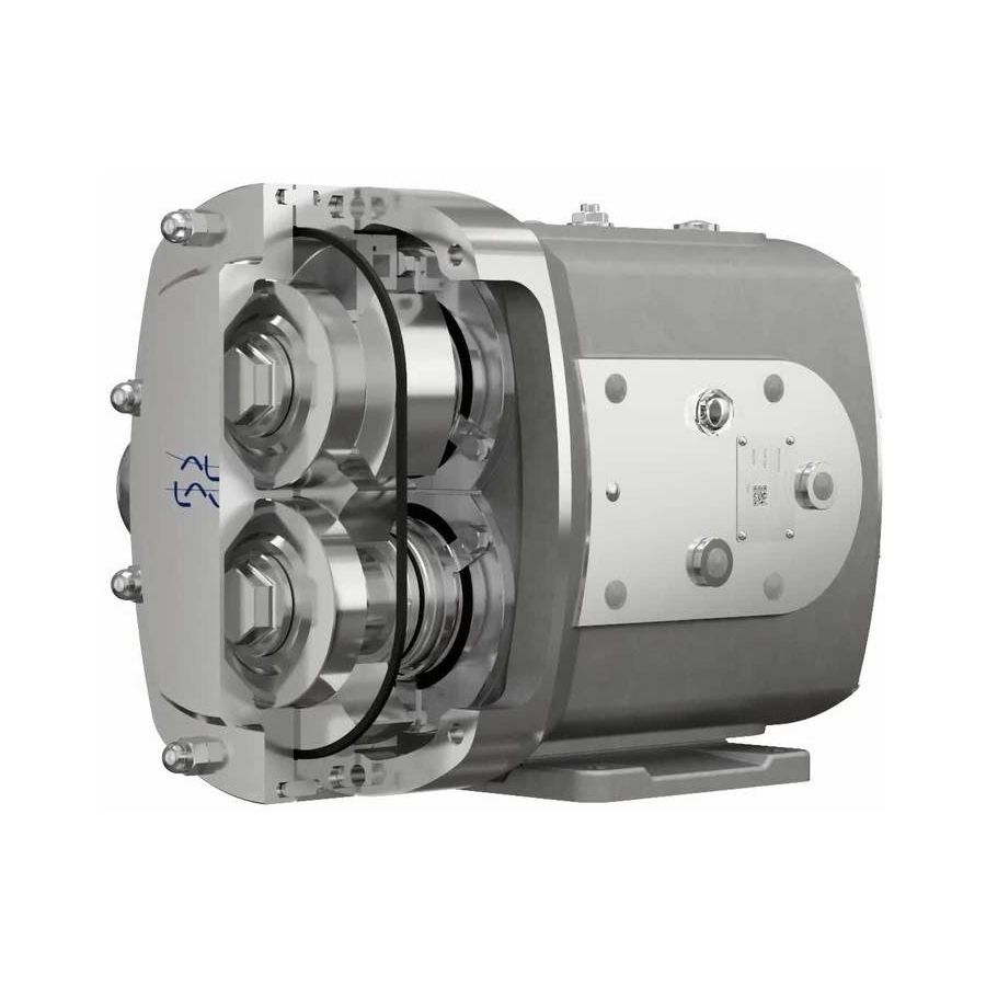
The drawing shown indicates main components of the pump unit. The DuraCirc range has a universal gearbox design which enables the flexibility of mounting pumps with the inlet and outlet ports in either a vertical or horizontal plane. The port orientation, vertical or horizontal, may be changed by moving one of two available bolt-on feet on the gearbox. - Page 8 2 General information Noise levels Under certain operating conditions pumps and/or drives and/or the systems within which they are installed can produce sound pressure levels in excess of 80dB[A]. It recommended that the noise level is measured during commissioning, running on normal operating conditions and appropriate personal protective equipment used where necessary.
-
Page 9: Safety
Trainees can perform tasks under the supervision of an experienced employee. People in general: The public shall not have access to the supplied product. How to contact Alfa Laval Contact details for all countries are continually updated on our website. Please visit www.alfalaval.com to access the information directly. -
Page 10: Warning Signs
3 Safety 3.2 Warning signs General warning Dangerous electrical voltage Caustic agents Hot Surfaces 200002348-1-EN-GB... -
Page 11: Safety Precautions
Never put your hands or fingers inside the port connections or anywhere close to rotating parts. Always have the drive electrically connected by authorized personnel. (see the motor instructions supplied with the drive unit.) Alfa Laval recommends the supply disconnecting device shall be in accordance with EN60204-1. Operation: Always read the technical data thoroughly. - Page 12 3 Safety Transportation: Transportation of the pump or the pump unit: Never lift or elevate in any way other than described in this manual Always drain the pump head and accessories of any liquid Always ensure that no leakage of lubricants can occur Always transport the pump in its upright position Always ensure that the unit is securely fixed during transportation Always use original packaging or similar during transportation...
-
Page 13: Installation
4 Installation 4.1 Unpacking, handling and storage Always ensure any personnel undertaking lifting operations have the suitable experience and training to do so safely. Ensure any lifting equipment used is in good condition and has been suitably tested, using lifting lugs when applied. -
Page 14: Recycling Information
• At end of use, the equipment shall be recycled according to relevant, local regulations. Beside the equipment itself, any hazardous residues from the process liquid must be considered and dealt within a proper manner. When in doubt, or in the absence of local regulations, please contact the local Alfa Laval sales company. 200002348-1-EN-GB... -
Page 15: System Design, Installation And Operation
Installation 4 4.3 System design, installation and operation When designing, installing and operating pipework systems where pumps are used, especially where the pumped media is viscous, there are general recommendations and good engineering practices that should be employed to ensure long term, reliable pump and system operation. Design - Confirm the Net Positive Suction Head (NPSH) available from the system exceeds the NPSH required by the pump, as this is crucial for ensuring the smooth operation of the pump and preventing... - Page 16 4 Installation Table of Maximum Forces and Moments 3206-0006 Port Forces Moments Size Units F (x, y or z) F (total) Units M (x, y or z) M (total) 25mm 1” Ibf.ft 40mm 1.5” Ibf.ft 50mm 2” Ibf.ft 65mm 2.5” Ibf.ft 80mm 3”...
- Page 17 Installation 4 Direction of flow: The direction of flow is dictated by the direction of rotation of the drive shaft. Reversing the direction of rotation will reverse the flow direction. 3206-0007 3206-0008 A Suction A Suction B Discharge B Discharge Pump Lubrication: The pump will be supplied pre-filled with food grade (NSF H-1) oil as standard.
- Page 18 All oils are poly-alpha-olefin based please check compatibility before mixing with other base oils. Baseplate Foundations Pumps when supplied with a drive unit are normally mounted on a baseplate. Alfa Laval standard positive displacement pump baseplates have pre-drilled fixing holes to accept base retaining bolts. To provide a permanent rigid support for securing the pump unit, a foundation is required which will also absorb vibration, strain or shock on the pumping unit.
- Page 19 Installation 4 Ball Foot Baseplate with Adjustable Feet The pump can be supplied with an optional ball foot baseplate with height adjustable feet. When used: Ensure the floor is level and is able to support the weight of the complete unit Ensure the unit is supported by all feet equally 3A Approved Ball Foot Baseplate with Adjustable Feet For 3A approved mounted pumps a 3A approved ball foot baseplate is required which has additional...
- Page 20 4 Installation Parallel Misalignment Measure 4 positions at 90° around coupling Coupling size Dimension A Maximum 0.3 mm 0.3 mm 0.3 mm 0.4 mm 0.4 mm 3206-0012 0.4 mm 0.5 mm 0.5 mm Angular Misalignment Measure 4 positions at 90° around coupling Coupling size Dimension A Maximum 1°...
-
Page 21: Flushing Seal Arrangement And Pre-Start Up Checks
Installation 4 4.4 Flushing seal arrangement and pre-start up checks A flushed seal arrangement may be fitted in order to cool, heat or clean the seal area (dependant on application). It is important that: • The flush is correctly connected (see diagram). - Page 22 4 Installation Flushing fluid. The choice of flushing fluid is dependent upon the fluid being pumped and duty conditions i.e. pressure and temperature. Usually water is used for cooling or flushing water-soluble products. For both single flushed and double mechanical seal arrangements the temperature of the flush media should never be allowed to exceed the maximum temperature of the pumped media.
-
Page 23: Maintenance
5 Maintenance 5.1 Cleaning in place (CIP) The DuraCirc pump range has been designed for Clean in Place (CIP) operation with both 3A and EHEDG certification. However, due to variations in pumped products, system design, cleanliness requirements and chemicals used we recommend that users develop suitable CIP processes during commissioning on normal operating conditions and products and verify these meet the required levels of cleanliness ensuring a minimum flow velocity of 1.5m/s. - Page 24 - Ensure the pump is fully flushed after passivation with clean water to ensure no residue remains. If you have any questions regarding other aggressive chemicals, please contact Alfa Laval for assistance.
-
Page 25: Maintenance Schedule
Maintenance 5 5.2 Maintenance schedule It is advisable to install pressure gauges on both sides of the pump the DuraCirc pump range. Maintenance schedule NOTE Below checks to be carried out when the pump is not operational, and any electrical supply has been safely disconnected and locked so accidental operation cannot occur. - Page 26 5 Maintenance Rotor Nut P-Ring Elastomer Replacement Interval It is recommended that the rotor nut elastomer seal is replaced every 12 months to maintain a bacteria tight seal. Rotor Nut P-Ring Elastomer Inspection Periodically inspect the rotor nut elastomer seal for any discoloration, nicks, or cracks. If any of the defects above are noticed, the elastomer seal must be replaced following the procedure below for 3A compliance: Cleaning Procedure for Soiled Rotor Nut Tapped Hole (3A)
-
Page 27: Dismantling
Maintenance 5 5.3 Dismantling Before dismantling the pump refer to safety precautions in Section 3. Refer to the exploded diagram and parts list in Section 7. NOTE: It is recommended to mark the positions of the rotors and rotorcase (e.g. Top/Bottom or Left/ Right) prior to removal to ensure parts are refitted in the same position. - Page 28 5 Maintenance 3206-0058 1. Remove rotorcase retaining screws (11). 2. Remove rotorcase (2) tapping both sides with a soft mallet if required. 3. If Double Mechanical seals are fitted remove from the shaft. Note: Shim retainer (13) and Shims (12) should not be removed unless rotor clearances require resetting.
- Page 29 Maintenance 5 3206-0059 Removing gland guards seal retainers 1. Remove screws (40). 2. Then remove gland guards (22) and seal retainers (34). 3. Remove the lip seals (36) and seal retainer o-rings (37) from the seal retainers and dispose. It is essential to renew the lip seal and o-ring prior to 3206-0023 reassembly.
- Page 30 5 Maintenance Removing timing gears 1. Lock the timing gear in position by placing a small soft rod between the gear teeth. 2. Loosen the torque lock assembly screws (39) but do not remove fully. 3. Remove gears (36) and torque lock assembly from the shafts (51 and 52) NOTE 3206-0025...
- Page 31 Maintenance 5 10 Rear Bearing Removal 1. Remove the shaft circlip (59) from the shaft (51 and 52) 2. Mount the shafts vertically in a press with a tool positively located against the rear bearing inner race (58) as shown and apply pressure to the top of the shaft so that the shaft moves through the bearing.
- Page 32 5 Maintenance 11 Front Bearing Removal 1. Remove the shafts from the press and hold in a vice using soft jaws to protect the areas where the lip seals will be located. 2. Bend the tab on the tabbed lock washer (56) up and remove the bearing nuts (57) using a ‘C’...
-
Page 33: Assembly
Maintenance 5 5.4 Assembly NOTE: Ensure all screws and nuts are torqued to the values stated in Section 6. Fitting bearings to shafts Take care not to damage shaft surfaces, in particular where the lip seals will be located. On DuraCirc 32 to 43 models, bearings do not require heating. - Page 34 5 Maintenance Fit the first bearing outer cup, bearing spacer (55) and rear bearing outer cup on the shaft as shown. Fit the second inner bearing cone to the shaft as per Step 2 above. 3206-0070 1. DuraCirc models 52 to 74 only: Allow bearings to cool to ambient temperature.
- Page 35 Maintenance 5 DuraCirc 52 to 74 DuraCirc models 52 to 74 only: Heat the rear bearing (58) using a bearing heater to C / 239 Place the bearing (58) (Inner race part only on the DuraCirc models 32 to 43) on the shaft as shown ensuring a positive fit against the shaft shoulder using a press and appropriate tool if required.
- Page 36 5 Maintenance 10 Fitting Shaft Assemblies. DuraCirc models 32 to 43 only: 1. Lightly oil the rear bearing bores of the gearcase (31) with gearbox oil. 2. Fit first bearing circlip (60) in the inner most groove in the rear bearing bore of the gearcase (31).
- Page 37 Maintenance 5 14 Fitting and retainers and gland guards Clean the rear face of the seal retainers (14) and the front face of the gearcase (31), fit in position and tighten. 1. Check rotor alignment is correct by referring to the rotor abutment alignment in step 18 and adjust as required.
- Page 38 5 Maintenance 17 Checking rotor abutment alignment. Note: Incorrect setting of rotor alignment will damage the pump. 1. Set the position of the missing spline in the shafts (51 and 52) to approximately 90deg to each other (e.g. 12 o’clock and 3 o’clock).
- Page 39 Maintenance 5 1. Remove the rotor nuts (4) and rotors (3). 2. Remove the seal retainer (34) only from the shaft position marked with the dimple on the gearcase (3). 3. Remove this shaft only (either 51 or 52) from the gearcase and remove the gearbox shims (53).
- Page 40 5 Maintenance 1. Gradually tighten the TLA screws (62) in a circular pattern until hand tight and the shafts can be rotated. Ensure the TLA is pushed fully back on the shaft and that the timing gear is pulled forward during tightening to ensure correct placement.
- Page 41 Maintenance 5 1. Set the shafts (51 and 52) with the missing spline as per the diagram (shown with the rotorcase fitted for demonstration).*) * Missing Spline 2. If rotors (3) are not fitted then fit on the 3206-0051 shafts in the sequence shown in the diagram ensuring to align the missing spline in the rotor with the shafts.
- Page 42 5 Maintenance 25 Fitting gearcase cover 1. Remove all old gasket material from both mating faces and wipe clean with a solvent. Clean the bore of the gearcase cover (35) and press a new lip seal (38) into the cover until flush. 2.
- Page 43 Maintenance 5 27 Fitting and shimming of Rotorcase Whenever the rotor case and rotors have been removed it is good engineering practice to check the clearances of the pump to ensure they are within specification shown in the clearance charts before putting back in to operation.
- Page 44 5 Maintenance 1. Ensure the shim retainers are correctly fitted to the rotorcase (3) and that the shim retainer screws (14) are not sitting proud of the shim retainers (13). If the shims have been removed during disassembly and not been kept in the matched sets please follow the instructions in step 30.
- Page 45 Maintenance 5 1. Remove the rotor nuts, rotors and rotorcase and place face down on a suitable surface. 2. Remove the shim retainer screws (14), shim retainers (13) and shims (12) ensuring to make note of the position of each. 3.
- Page 46 5 Maintenance 1. Lightly lubricate and fit new P-ring elastomer (6) into the groove on the rotor nuts (4) ensuring the correct orientation. 2. Fit rotor nuts and tighten to torque shown in Section 6.1. Use a plastic (nylon) block to stop the rotors from turning during tightening.
-
Page 47: Primary Seals Removal And Fitting
Maintenance 5 5.5 Primary seals removal and fitting Single mechanical seal Mechanical seals are fragile. Take extreme care when handling. Clean components before fitting, checking there is no damage to sealing faces. New elastomeric parts should be fitted during assembly. Item Description Square Ring (Yellow ID mark) - Page 48 5 Maintenance Seal fitting NOTE Ensure all screws and nuts are torqued to the values stated in Section 6. 3206-0075 Model Dimension X (mm) 32/33/34 42/43 52/53/54 62/63 3206-0046 72/73/74 1. If the static assembly (105) was removed, align the line mark on front face of with the lugs in the bore of the rotorcase (2) and press back ensuring the drive ring is kept square to the bore until fully...
- Page 49 Maintenance 5 6. Lubricate the square ring elastomer (101) and fit to the rotary seal face (102) ensuring the rounded edge is fitted in to the radius of the seal face part as shown in the diagram. Note: the coloured dot should be facing away from the rotary seal face.
- Page 50 5 Maintenance Single flushed mechanical seal Item Description Square Ring (Yellow ID Mark) Rotary Seal Face Static Seal Face Squad Ring (White ID Mark) Static Assembly 3206-0047 Lip Seal Seal removal NOTE It is recommended to mark the positions of the rotors and rotorcase (e.g.
- Page 51 Maintenance 5 Seal fitting NOTE Ensure all screws and nuts are torqued to the values stated in Section 6. 1. Apply a small amount of suitable lubrication to the new lip seal (111) and press fit to the rear seal bore of the rotorcase (2) until flush with end of bore.
- Page 52 5 Maintenance Double flushed mechanical seal Item Description Square Ring (Yellow ID Mark) Rotary Seal Face Static Seal Face Squad Ring (White ID Mark) Static Assembly 3206-0048 Static Assembly (Outboard) Static O-ring (Outboard) Static Seal Face (Outboard) Rotary Assembly (Outboard) Rotary O-ring (Outboard) Seal removal NOTE...
- Page 53 Maintenance 5 Seal fitting NOTE Ensure all screws and nuts are torqued to the 3206-0080 values stated in Section 6. 1. Lightly lubricate the outboard rotary O-ring (110) with a suitable lubricant and fit on to shaft (51 and 52). 2.
- Page 54 5 Maintenance 10 O-ring Seal (Single and Flush) Item Description Sleeve Static Assembly, O-ring seal O-Ring, Primary O-Ring, Static O-Ring, Sleeve Outer 3206-0049 O-Ring, Sleeve Inner *Lipseal (flush version only) O-ring seal removal: NOTE It is recommended to mark the positions of the rotors and rotorcase (e.g.
- Page 55 Maintenance 5 3206-0071 12 O-ring seal fitting: NOTE: Ensure all screws and nuts are torqued to the values stated in Section 6. 1. Flushed seal only: Apply a small amount of suitable lubrication to the new lip seal (126) and press fit to the rear seal bore of the rotorcase (2) until flush with end of bore.
- Page 56 5 Maintenance 7. Refit the rotors (3), rotor nuts (4) and rotorcase cover (1) as per the main assembly instructions in Section 5.4 8. Flushed seals only - Refit the flush pipework and refill, checking for any leaks and correct operation before restarting the pump.
-
Page 57: Heating/Cooling Devices
Maintenance 5 5.6 Heating/Cooling devices The DuraCirc pumps have the option of being fitted with a heating/cooling jacket fitted on the rear of the rotorcase. These are to be used for heating the pump head to maintain the pumped media viscosity and reduce risk of any crystallisation/solidification of the pumped product occurring. - Page 58 5 Maintenance Reassembly 1. Wipe the mating surfaces of the rotorcase (2) and jacket (17) with a solvent and ensure the O-ring groove is clean and free of debris and damage (replace jacket if required). 2. Lightly lubricate new o-rings (18) and push firmly in the jacket O-ring groove.
-
Page 59: Troubleshooting
Maintenance 5 5.7 Troubleshooting 11 Noise and vibrations 1 No flow 6 Prime lost after starting 12 Pump element wear 2 Under capacity 7 Pump stalls when starting 13 Syphoning 3 Irregular discharge 8 Pump overheat 14 Seizure 4 Low discharge pressure 9 Motor overheats 15 Mechanical seal leakage 5 Pump will not prime... - Page 60 5 Maintenance Problem Probable Causes Solutions 1 2 3 4 5 6 7 8 9 10 Checks for obstructions i.e. closed valve Discharge pressure above Service system and change to prevent x x x x x x rated figure problem recurring Simplify discharge line to decrease pressure Increase flush flow rate Seal flushing inadequate...
-
Page 61: Technical Data
6 Technical data 6.1 Technical data 6.1.1 Approximate oil capacities Pump model Horizontal Ports Vertical Ports litres us.gal litres us.gal 32/33/34 0.13 0.24 42/43 0.26 0.40 52/53/54 0.61 0.92 62/63 1.22 1.74 72/73/74 10.3 1.82 2.72 6.1.2 Weights Typical Bare Shaft Pump kg (lb) Typical Pump with Drive Unit kg (lb) Pump model Port Orientation... - Page 62 6 Technical data 6.1.3 Tool requirements Pump Model Description Tool Required 32/33/34 42/43 52/53/54 62/63 72/73/74 Socket Size (mm Nut, Rotorcase Cover (8) Torque Setting (Nm) Torque Setting (lbft) Socket Size (mm Nut, Rotor (4) Torque Setting (Nm) Torque Setting (lbft) Socket Size (mm Screw, Rotor (11) Torque Setting (Nm)
- Page 63 Technical data 6 6.1.4 Pump Data Table Pump Displacement Port size Max. Working Pressure Max Speed litres/ Img gal / US gal / Model inch rev /min 100 rev 100 rev 0.03 0.66 0.79 1000 0.05 1.10 1.32 1000 0.12 2.64 3.17 1000...
- Page 64 6 Technical data 6.1.5 Seal Operating Limits Seal Type Maximum Speed Maximum Process Pressure Mechanical Seal (Sic/Carbon) Max. Pump Speed Mechanical Seal (Sic/Sic) Max. Pump Speed Max. Pump Pressure O-ring Seal Maximum Flush Pressures: Mechanical Seal – Single Flush = 0.5 bar / 7 psi Mechanical Seal –...
-
Page 65: Pumphead Clearance Information
Technical data 6 6.2 Pumphead Clearance information For pump head clearances please see separate addendum sheet. 200002348-1-EN-GB... - Page 66 6 Technical data 200002348-1-EN-GB...
-
Page 67: Parts List
7 Parts list 7.1 DuraCirc Pump Range 3206-0050 200002348-1-EN-GB... - Page 68 7 Parts list Pos. Denomination Cover, Rotorcase Rotorcase Rotor Nut, Rotor P-ring, Cover P-ring, Roter nut O-ring, Rotor shaft Nut, Dome Stud, Rotorcase Dowel, Rotorcase Screw, Rotorcase Shim, Rotorcase Retainer, Shim Screw, Shim retainer Heating jackets O-ring, Heating jacket Screw, Heating jacket Guard, gland Gearcase Foot, Vertical port...
- Page 69 Parts list 7 Pos. Denomination Sight glass Plug, Gearcase Plug, Blanking Plug, Blanking Shaft, Drive Shaft, Auxillary Shim, Gearbox Bearing, Front Spacer, Bearing Washer, tab lock Nut, Shaft Bearing, Rear Circlip, Shaft Circlip, Bearing *(DuraCirc 32 to 43 Only) Timing Gear Torque Locking Assembly (TLA) Key, Drive 200002348-1-EN-GB...
Need help?
Do you have a question about the DuraCirc Range and is the answer not in the manual?
Questions and answers