
Related Manuals for Alfa Laval LKH


Summary of Contents for Alfa Laval LKH
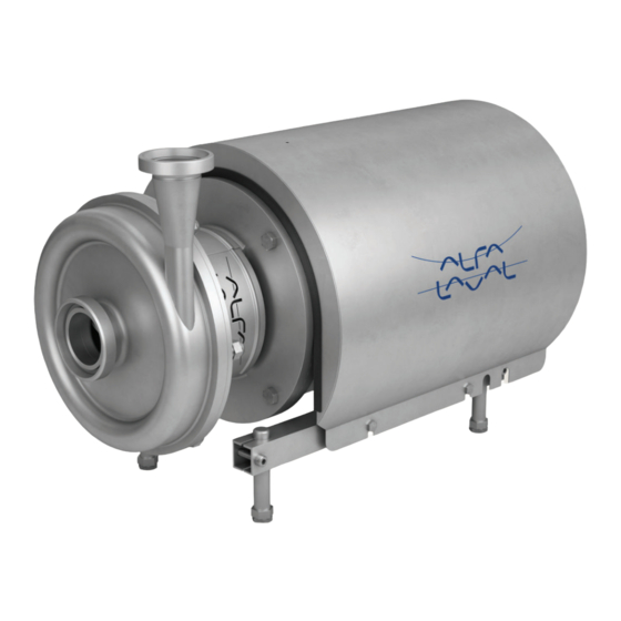
- Page 1 Instruction Manual LKH Centrifugal Pump 3000-0200 ESE00698-EN29 2020-12 Original manual...
- Page 2 CONTACT CSI FOR MORE INFORMATION | CSIDESIGNS.COM | SALES@CSIDESIGNS.COM | 417.831.1411...
-
Page 3: Table Of Contents
6.5. Noise emission ..................7. Parts list and service kits ................7.1. LKH-5 Sanitary version ................7.2. LKH-10, -15, -20, -25, -35, -40, -50, -60, -70, -75, -85, -90 sanitary version ..... 7.3. LKH - Product wetted parts ..............7.4. LKH - Motor-dependent parts .............. -
Page 4: Ec Declaration Of Conformity
+45 79 32 22 00 Phone No. hereby declare that Pump Designation LKH-5, LKH-10, LKH-15, LKH-20, LKH-25, LKH-35, LKH-40, LKH-45, LKH-50, LKH-60, LKH-70, LKH-85, LKH-90 Type Serial number from AAB000000001 to AAB999999999 Serial number from 10.000 to 1.000.000 Serial number from 100700000001-100799999999... -
Page 5: Safety
2 Safety Unsafe practices and other important information are emphasised in this manual. Warnings are emphasised by means of special signs. A A l l w w a a y y s s r r e e a a d d t t h h e e m m a a n n u u a a l l b b e e f f o o r r e e u u s s i i n n g g t t h h e e p p u u m m p p ! ! 2.1 Important information W W A A R R N N I I N N G G Indicates that special procedures must be followed to avoid serious personal injury. -
Page 6: Warning Signs
2 Safety Unsafe practices and other important information are emphasised in this manual. Warnings are emphasised by means of special signs. A A l l w w a a y y s s r r e e a a d d t t h h e e m m a a n n u u a a l l b b e e f f o o r r e e u u s s i i n n g g t t h h e e p p u u m m p p ! ! 2.2 Warning signs G G e e n n e e r r a a l l w w a a r r n n i i n n g g : : D D a a n n g g e e r r o o u u s s e e l l e e c c t t r r i i c c a a l l v v o o l l t t a a g g e e : :... -
Page 7: Safety Precautions
A A l l w w a a y y s s handle lye and acid with great care. N N e e v v e e r r use the pump for products not mentioned in the Alfa Laval pump selection program. - Page 8 A A l l w w a a y y s s use suitable transport device ie. forklift or pallet lifter S S t t o o r r a a g g e e : : Ideally as a guide Alfa Laval would recommend: - Store supplied product as supplied in original packaging...
-
Page 9: Unpacking/Delivery
3. Motor instructions. C C A A U U T T I I O O N N Alfa Laval cannot be held responsible for incorrect unpacking. W W A A R R N N I I N N G G : : Be aware that certain pump configurations can tilt, and therefore cause injuries to feet or fingers. - Page 10 3 Installation S S t t e e p p 4 4 Remove the shroud before lifting! Always remove the shroud, if fitted, before lifting the pump. 3000-0202 S S t t e e p p 5 5 O O N N L L Y Y L L K K H H - - 8 8 5 5 a a n n d d L L K K H H - - 9 9 0 0 Do N N O O T T use eyebolt in casing to lift the pump.
-
Page 11: Installation
W W A A R R N N I I N N G G : : Alfa Laval recommends the supply disconnecting device shall be in accordance with EN60204-1. Always disconnect the supply disconnecting device safely after installation before continuing the installation. - Page 12 - See pre-use check in section 3.3 Pre-use check - pump without impeller screw. The large pump sizes are very heavy. Alfa Laval therefore recommends the use of a lifting crane when handling the pump. S S t t e e p p 3 3 Check that the flow direction is correct.
- Page 13 - See pre-use check in section 3.3 Pre-use check - pump without impeller screw. The large pump sizes are very heavy. Alfa Laval therefore recommends the use of a lifting crane when handling the pump. S S t t e e p p 6 6 Ensure correct alignment of pump inlet and outlet with piping system.
- Page 14 - See pre-use check in section 3.3 Pre-use check - pump without impeller screw. The large pump sizes are very heavy. Alfa Laval therefore recommends the use of a lifting crane when handling the pump. No gaps between connections on pump inlet and inlet pipe, and pump outlet and outlet pipe.
- Page 15 - See pre-use check in section 3.3 Pre-use check - pump without impeller screw. The large pump sizes are very heavy. Alfa Laval therefore recommends the use of a lifting crane when handling the pump. 3000-0216 Ensure stud bolts in casing are aligned with holes in backplate.
- Page 16 The large pump sizes are very heavy. Alfa Laval therefore recommends the use of a lifting crane when handling the pump. Always ensure the adaptor shield and motor fan guard are present and mounted correctly and allow no access to rotating parts before installing and starting the pump.
-
Page 17: Pre-Use Check - Pump Without Impeller Screw
3 Installation Read the instructions carefully and pay special attention to the warnings! LKH-5 to -60 comes without impeller screw as standard but can be supplied with one. Check the direction of rotation of the impeller before operation. - See the indication label on the pump. - Page 18 3 Installation Read the instructions carefully and pay special attention to the warnings! LKH-5 to -60 comes without impeller screw as standard but can be supplied with one. Check the direction of rotation of the impeller before operation. - See the indication label on the pump.
-
Page 19: Pre-Use Check - Pump With Impeller Screw
3 Installation Read the instructions carefully and pay special attention to the warnings! LKH-5 to -60 comes without impeller screw as standard but can be supplied with one. Check the direction of rotation of the impeller before operation. - See the indication label on the pump. -
Page 20: Recycling Information
3 Installation Read the instructions carefully and pay special attention to the warnings! LKH-5 to -60 comes without impeller screw as standard but can be supplied with one. Check the direction of rotation of the impeller before operation. - See the indication label on the pump. -
Page 21: Operation
A A l l w w a a y y s s read the technical data thoroughly. See chapter 6 Technical data C C A A U U T T I I O O N N Alfa Laval cannot be held responsible for incorrect operation/control. S S t t e e p p 2 2 N N e e v v e e r r touch the pump or the pipelines when pumping hot liquids or when sterilising. - Page 22 1. Connect the inlet of the flushing liquid correctly. (1/8” G). 2. Regulate the water supply correctly. = 70°C = 1 bar (flush seal) For LKH-85: connect inlet/outlet of the flushing liquid directly on LKH 5-60 = the flushing housing. (ø6 tube). 5 bar (DMS)
-
Page 23: Trouble Shooting
4 Operation Pay attention to possible faults. Read the instructions carefully. 4.2 Trouble shooting N N O O T T E E ! ! Read the maintenance instructions carefully before replacing worn parts. R R e e m m e e d d y y P P r r o o b b l l e e m m C C a a u u s s e e / / r r e e s s u u l l t t Motor overloaded... -
Page 24: Recommended Cleaning
4 Operation The pump is designed for cleaning in place (CIP). CIP = Cleaning In Place. Study the instructions carefully and pay special attention to the warnings! NaOH = Caustic Soda. = Nitric acid. 4.3 Recommended cleaning S S t t e e p p 1 1 C C a a u u s s t t i i c c d d a a n n g g e e r r ! ! A A l l w w a a y y s s handle lye and acid with great care. - Page 25 4 Operation The pump is designed for cleaning in place (CIP). CIP = Cleaning In Place. Study the instructions carefully and pay special attention to the warnings! NaOH = Caustic Soda. = Nitric acid. S S t t e e p p 4 4 A A l l w w a a y y s s r r i i n n s s e e ! ! A A l l w w a a y y s s rinse well with clean water after using a cleaning agent.
-
Page 26: Maintenance
N N o o t t e e : : If the pump is supplied with FEP O-rings, Alfa Laval recommends that the casing O-ring is replaced during pump maintenance. CONTACT CSI FOR MORE INFORMATION | CSIDESIGNS.COM | SALES@CSIDESIGNS.COM | 417.831.1411... - Page 27 5 Maintenance Maintain the pump with care. Read the instructions carefully and pay special attention to the warnings! Always keep spare shaft seals and rubber seals in stock. See separate motor instructions. Check the pump for smooth operation after service. S S a a f f e e t t y y c c h h e e c c k k A visual inspection of adaptor shield and motor fan guard must be carried out every 12 months.
-
Page 28: Cleaning Procedure
5 Maintenance 5.2 Cleaning Procedure C C l l e e a a n n i i n n g g p p r r o o c c e e d d u u r r e e f f o o r r s s o o i i l l e e d d i i m m p p e e l l l l e e r r s s c c r r e e w w t t a a p p p p e e d d h h o o l l e e : : W W a a r r n n i i n n g g : : Always follow the instructions in the safety data sheet for the cleaning agent. -
Page 29: Dismantling Of Pump/Shaft Seals
S S t t e e p p 1 1 A. LKH-5: Remove screws (56), spring washers (56a), clamps (55+55a) and pump casing (29). B. LKH-10 to 90: Unscrew cap nuts (24) and remove washers (24a) and pump casing (29). 3000-0229... - Page 30 5 Maintenance Read the instructions carefully. The items refer to the parts list and service kits section. Handle scrap correctly. : Relates to the shaft seal. S S t t e e p p 3 3 Remove screw (23) and safety guard (22). 3000-0231 S S t t e e p p 4 4 1.
- Page 31 2. Remove rotating seal rings (14) and drive ring (52) from spring (13). 3. Remove O-rings (15) from rotating seal rings (14). 4. LKH-70 to 90: Remove cups (54) from rotating seal rings. 3000-0236 S S t t e e p p 9 9 D D o o u u b b l l e e m m e e c c h h a a n n i i c c a a l l s s h h a a f f t t s s e e a a l l : : 1.
-
Page 32: Assembly Of Pump/Single Shaft Seal
If change from double mechanical shaft seal to single shaft seal the shaft needs to be adjusted. see Section 5.7 Adjustment of shaft (LKH-5) and Section 5.8 Adjustment of shaft (LKH-10 to -90). S S t t e e p p 2 2 1. - Page 33 5 Maintenance Read the instructions carefully. The items refer to the parts list and service kits section. Handle scrap correctly. : Relates to the shaft seal. S S t t e e p p 5 5 1. Clean the sealing surfaces with contact cleaner before fitting back plate (25).
- Page 34 2. Adjust pump casing to the right position. A. LKH-5: Tighten nuts (20) for back plate (25) and tighten screws (56). B. LKH-10 to -90: Tighten nuts (20) for back plate (25) and tighten cap nuts (24), according to torque values in chapter 6 Technical data.
-
Page 35: Assembly Of Pump/Flushed Shaft Seal
If change from double mechanical shaft seal to flushed shaft seal the shaft needs to be adjusted. see Section 5.7 Adjustment of shaft (LKH-5) and Section 5.8 Adjustment of shaft (LKH-10 to -90). S S t t e e p p 2 2 1. - Page 36 5 Maintenance Read the instructions carefully. The items refer to the parts list and service kits section. Lubricate the rubber seals before fitting them. : Relates to the shaft seal. S S t t e e p p 5 5 Lubricate O-ring (26) and slide it onto back plate (25).
- Page 37 2. Tighten nuts (20) for back plate (25). A. LKH-5: Tighten nuts (20) for back plate (25) and tighten screws (56). B. LKH-10 to -90: Fit washers (24a) and cap nuts (24) and tighten, according to the torque values in chapter 6 Technical data. 3000-0247 LKH-85 and LKH-90 CONTACT CSI FOR MORE INFORMATION | CSIDESIGNS.COM | SALES@CSIDESIGNS.COM | 417.831.1411...
-
Page 38: Assembly Of Pump/Double Mechanical Shaft Seal
3. Fit spring (13) on one of the rotating seal rings (14) and place the drive ring (52) in between. S S t t e e p p 2 2 1. LKH-70 to -90: Turn the drive ring (52) in order to place it correctly on the pump shaft (7). - Page 39 5 Maintenance Read the instructions carefully. The items refer to the parts list and service kits section. Lubricate the rubber seals before fitting them. : Relates to the shaft seal. S S t t e e p p 6 6 Lubricate O-ring (26) and slide it onto back plate (25).
- Page 40 2. Tighten nuts (20) for back plate (25). A. LKH-5: Fit clamps (55+55a), spring washers (56a) and screws (56) and tighten. B. LKH-10 to -90: Fit washers (24a) and cap nuts (24) and tighten, according to torque values in chapter 6 Technical data. 3000-0247 LKH-85 and LKH-90 CONTACT CSI FOR MORE INFORMATION | CSIDESIGNS.COM | SALES@CSIDESIGNS.COM | 417.831.1411...
-
Page 41: Adjustment Of Shaft (Lkh-5)
Read the instructions carefully. The items refer to the parts list and service kits section. Lubricate the rubber seals before fitting them. : Relates to the shaft seal. 5.7 Adjustment of shaft (LKH-5) S S t t e e p p 1 1 1. Loosen screws (6). - Page 42 1. Fit impeller (27) on stub shaft (7). 2. Ensure that the clearance between the impeller and back plate (25) is correct: 0.5 mm (0.02 inch) for LKH-5. The clearance can be adjusted by knocking gently with a plastic hammer.
-
Page 43: Adjustment Of Shaft (Lkh-10 To -90)
Lubricate the rubber seals before fitting them. : Relates to the shaft seal. 5.8 Adjustment of shaft (LKH-10 to -90) L L K K H H - - 7 7 0 0 t t o o - - 9 9 0 0 For securing the best fixture to the motor shaft ensure the following: - Conical surfaces on the pump shaft and compression rings are applied with grease. - Page 44 1. Fit impeller (27) on stub shaft (7). 2. Ensure that the clearance between the impeller and back plate (25) is correct: 0.5 mm (0.02 inch) for LKH-10 to 60 and 1.0 mm (0.039 inch) for LKH-70 to -90. 3. Tighten screws (6) evenly until the stub shaft (7) cannot move on the motor shaft.
-
Page 45: Technical Data
The LKH pump is a highly efficient and econominal centrifugal pump, which meets the requirements of sanitary and gentle product treatment and chemical resistsnce. LKH is available in the following sizes LKH-5, -10, -15, -20, -25, -35, -40, -50, -60, -70, -75, -85 and -90. -
Page 46: Technical Data
For relubrication intervals see motor name plate. For further information contact your local Alfa Laval Technical Support. W W a a r r n n i i n n g g : : P P o o l l y y u u r r e e a a b b a a s s e e d d g g r r e e a a s s e e ( ( u u s s e e d d o o n n e e g g . . L L K K H H 8 8 5 5 m m o o t t o o r r s s ) ) m m u u s s t t n n o o t t b b e e m m i i x x e e d d w w i i t t h h L L i i t t h h i i u u m m b b a a s s e e d d g g r r e e a a s s e e o o r r v v i i c c e e v v e e r r s s a a . . -
Page 47: Noise Emission
MR-300 FM-OS The above LKH noise levels are the same for LKHPF, LKHI, LKH UltraPure, LKH Evap and LKHex. The above SolidC noise levels are the same for SolidC UltraPure. The noise measurements have been carried out using the original motor and shroud, at the approximate Best Efficiency Point (BEP) with water at ambient temperature and at 50 Hz. -
Page 48: Parts List And Service Kits
7 Parts list and service kits The drawing shows LKH pump, sanitary version. 7.1 LKH-5 Sanitary version 3000-0263 US legs are different to the ones shown. For further information see US spare parts. Impeller screw Fitting of legs Fitting of back plate 0.75-1.1 kW... -
Page 49: Lkh-10, -15, -20, -25, -35, -40, -50, -60, -70, -75, -85, -90 Sanitary Version
7 Parts list and service kits The drawing shows the LKH pump, sanitary version. 7.2 LKH-10, -15, -20, -25, -35, -40, -50, -60, -70, -75, -85, -90 sanitary version 3000-0264 LKH10 -75 LKH-85 and LKH-90 US legs are different to the ones shown. For further information see US spare parts. -
Page 50: Lkh - Product Wetted Parts
7 Parts list and service kits The drawing shows the LKH pump, sanitary version. 7.3 LKH - Product wetted parts 50 51 15 52 3000-0265 * If inducer (57) is retrofitted. Pump inlet may have to be slightly ground. CONTACT CSI FOR MORE INFORMATION | CSIDESIGNS.COM | SALES@CSIDESIGNS.COM | 417.831.1411... - Page 51 7 Parts list and service kits The drawing shows the LKH pump, sanitary version. P P a a r r t t s s l l i i s s t t Pos. Denomination Washer Cap nut Washer Back plate O-ring ♦∆▲...
-
Page 52: Lkh - Motor-Dependent Parts
7 Parts list and service kits The drawing shows the LKH pump, sanitary version. 7.4 LKH - Motor-dependent parts 50 51 15 52 3000-0265 * If inducer (57) is retrofitted. Pump inlet may have to be slightly ground. CONTACT CSI FOR MORE INFORMATION | CSIDESIGNS.COM | SALES@CSIDESIGNS.COM | 417.831.1411... - Page 53 7 Parts list and service kits The drawing shows the LKH pump, sanitary version. P P a a r r t t s s l l i i s s t t Pos. Denomination Motor ABB Motor ABB Shroud Screw...
-
Page 54: Lkh - Shaft Seal
7 Parts list and service kits The drawing shows the LKH pump, sanitary version. 7.5 LKH - Shaft seal 50 51 15 52 3000-0265 * If inducer (57) is retrofitted. Pump inlet may have to be slightly ground. CONTACT CSI FOR MORE INFORMATION | CSIDESIGNS.COM | SALES@CSIDESIGNS.COM | 417.831.1411... - Page 55 7 Parts list and service kits The drawing shows the LKH pump, sanitary version. P P a a r r t t s s l l i i s s t t Pos. Denomination Drive ring Stationary seal ring O-ring...
- Page 56 7 Parts list and service kits The drawing shows the LKH pump, sanitary version. D D e e n n o o m m i i n n a a t t i i o o n n E E P P D D M M...
- Page 57 ♦∆▲ Conversion kit - single to double mechanical shaft seal: Please order double mechanical service kit + pos. 40a+41+42 (for LKH-85 pos 40a+41+42a). Conversion kit single to flushed shaft seal: Please order Flushed service kit + pos. 10+40+41+42 (for LKH85 pos.10+ 40+41+42a).
- Page 58 CONTACT CSI FOR MORE INFORMATION | CSIDESIGNS.COM | SALES@CSIDESIGNS.COM | 417.831.1411...
- Page 59 CONTACT CSI FOR MORE INFORMATION | CSIDESIGNS.COM | SALES@CSIDESIGNS.COM | 417.831.1411...
- Page 60 © 1999-02 Alfa Laval Corporate AB This document and its contents is owned by Alfa Laval Corporate AB and protected by laws governing intellectual property and thereto related rights. It is the responsibility of the user of this document to comply with all applicable intellectual property laws. Without limiting any rights related to this document, no part of this document may be copied, reproduced or transmitted in any form or by any means (electronic, mechanical, photocopying, recording, or otherwise), or for any purpose, without the expressed permission of Alfa Laval Corporate AB.
Need help?
Do you have a question about the LKH and is the answer not in the manual?
Questions and answers