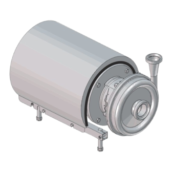
Alfa Laval LKH-5 Installation Manual
Centrifugal pump
Hide thumbs
Also See for LKH-5:
- Instruction manual (56 pages) ,
- Instruction manual (28 pages) ,
- Instruction manual (58 pages)

Subscribe to Our Youtube Channel
Related Manuals for Alfa Laval LKH-5


Summary of Contents for Alfa Laval LKH-5
- Page 1 LKH Centrifugal Pump 3000-0200 Instruction Manual Lit. Code 200007897-1-EN-GB BRITISH ENGLISH...
- Page 2 © Alfa Laval Corporate AB 2023-05 This document and its contents are subject to copyrights and other intellectual property rights owned by Alfa Laval Corporate AB. No part of this document may be copied, re-produced or transmitted in any form or by any means, or for any purpose, without Alfa Laval Corporate AB’s prior express written permission. Information and services provided in this document are made as a benefit and service to the user, and no representations or warranties are made about the accuracy or suitability of this information and these services for any purpose.
-
Page 3: Table Of Contents
Dismantling of pump/shaft seals................32 Assembly of pump/single shaft seal................ 35 Assembly of pump/flushed shaft seal..............38 Assembly of pump/double mechanical shaft seal........... 41 Adjustment of shaft (LKH-5)..................45 Adjustment of shaft (LKH-10 to -90)................ 47 6 Technical data ......................49 Technical data......................49 Relubrication intervals..................... - Page 4 Parts List and Exploded View - drawing..............55 8 Spare Parts .........................57 Ordering Spare Parts....................57 Alfa Laval Service....................57 9 General Installation Guidelines ..............59 LKH guidelines......................59 Hygienic recommendations..................59 Adapter details......................60...
-
Page 5: Declarations Of Conformity
1 Declarations of Conformity 1.1 EU Declaration of Conformity The Designated Company Alfa Laval Kolding A/S, Albuen 31, DK-6000 Kolding, Denmark, +45 79 32 22 00 Company name, address and phone number Hereby declare that Pump Designation LKH-5, LKH-10, LKH-15, LKH-20, LKH-25, LKH-35, LKH-40, LKH-45, LKH-50, LKH-60, LKH-70, LKH-85,... -
Page 6: Declaration Of Conformity
1 Declarations of Conformity 1.2 UK Declaration of Conformity UK Declaration of Conformity The Designated Company Alfa Laval Kolding A/S, Albuen 31, DK-6000 Kolding, Denmark, +45 79 32 22 00 Company name, address and phone number Hereby declare that Pump... -
Page 7: Safety
Not following the instructions can result in serious accidents. This documentation describes the authorized way to use the supplied product. Alfa Laval will take no responsibility for injury or damage if the equipment is used in any other way. This Instruction manual is designed to provide the user with the information to perform tasks safely for all phases in the lifetime of the supplied product. -
Page 8: Warning Signs
2 Safety 2.2 Warning signs Warning signs General warning: Dangerous electrical voltage: Caustic agents: 200007897-1-EN-GB... -
Page 9: Safety Precautions
Always handle lye and acid with great care. Never use the pump for products not mentioned in the Alfa Laval pump selection program. The Alfa Laval pump selection program can be acquired from your local Alfa Laval sales company. - Page 10 Always ensure that the unit is securely fixed during transportation Always use the original packaging or similar during transportation Always use suitable transport device ie. forklift or pallet lifter Storage: Ideally as a guide Alfa Laval would recommend: • Store supplied product as supplied in original packaging •...
-
Page 11: Installation
3 Installation 3.1 Unpacking/delivery CAUTION Alfa Laval cannot be held responsible for incorrect unpacking. WARNING Be aware that certain pump configurations can tilt, and therefore cause injuries to feet or fingers. The pump should be supported underneath the adaptor, when not installed in the process line. - Page 12 3 Installation Always remove the shroud, if fitted, before lifting the pump. 3000-0202 Remove the shroud before lifting! ONLY LKH-85 and LKH-90 Do NOT use eyebolt in casing to lift the pump. The eyebolt is for casing removal only. 3000-0203 200007897-1-EN-GB...
-
Page 13: Installation
- See pre-use check in section 3.3 and 3.4 Pre-use check. The large pump sizes are very heavy. Alfa Laval therefore recommends the use of a lifting crane when handling the pump. WARNING Always read the technical data thoroughly. (See chaper... - Page 14 3 Installation Check that the flow direction is correct. O: Outlet I: Inlet 3000-0205 1. Ensure that the pipelines are routed correctly. 2. Ensure that the connections are tight. 3. Remember seal rings. Few bends 3000-0206 Correct Avoid stress on the pump. Piping system must be self-supported.
- Page 15 Installation 3 Example of piping system self-supported. 3000-0208 3000-0207 Ensure correct alignment of pump inlet and outlet with piping system. Alignment can be done by adjusting the pump legs. 3000-0210 3000-0209 Centre of inlet and outlet to be aligned with centre of piping system. 3000-0211 200007897-1-EN-GB...
- Page 16 3 Installation No gaps between connections on pump inlet and inlet pipe, and pump outlet and outlet pipe. 3000-0212 Angel between connections on pump inlet and inlet pipe, pump outlet and outlet pipe not allowed. 3000-0213 200007897-1-EN-GB...
- Page 17 Installation 3 Ensure correct alignment of pump casing and pump backplate. Angle not allowed. Alignment can be done by adjusting the pump legs. 3000-0215 3000-0216 Ensure stud bolts in casing are aligned with holes in backplate. 3000-0215 3000-0216 200007897-1-EN-GB...
- Page 18 In case of shaft seal leakage, the media will drip from the slot in the bottom of the adaptor. In case of shaft seal leakage, Alfa Laval recommends putting a drip tray underneath the slot to collect the leakage. WARNING Always ensure the adaptor shield and motor fan guard are present and mounted correctly and allow no access to rotating parts before installing and starting the pump.
-
Page 19: Pre-Use Check - Pump Without Impeller Screw
Always remove the impeller before checking the direction of rotation. Never start the pump if the impeller is fitted and the pump casing is removed. 1. a. LKH-5: Remove screws (56), spring washers (56a), clamps (55+55a) and pump casing (29). -
Page 20: Pre-Use Check - Pump With Impeller Screw
3 Installation 1. Fit pump casing (29). 2. a. LKH-5: Fit clamps (55+55a), spring washers (56a) and tighten screws (56). b. LKH-10 to -60: Fit washers (24a) and tighten cap nuts (24), according to 3000-0220 torque values in chapter 6 Technical data. -
Page 21: Recycling Information
When in doubt, or in the absence of local regulations, please contact your local Alfa Laval sales company. 200007897-1-EN-GB... -
Page 23: Operation
Read the instructions carefully and pay special attention to the warnings! 4.1 Operation/Control CAUTION Always read the technical data thoroughly. See chapter 6 Technical data. Alfa Laval cannot be held responsible for incorrect operation/control. WARNING Never touch the pump or the pipelines when pumping hot liquids or when sterilising. 3000-0222... - Page 24 4 Operation Double mechanical/flushed shaft seal: 1. Connect the inlet of the flushing liquid correctly. (1/8¨. 2. Regulate the water supply correctly. For LKH-85: connect inlet/outlet of the flushing liquid directly on the flushing housing. (Ø6 tube). 3007-0146 O: Outlet I: Inlet = 70°C = 1 bar (flush...
-
Page 25: Trouble Shooting
Operation 4 4.2 Trouble shooting Pay attention to possible faults. Read the instructions carefully. NOTE Read the maintenance instructions carefully before replacing worn parts. Problem Cause/result Remedy • Pumping of viscous liquids • Larger motor or smaller impeller Motor overloaded •... -
Page 26: Recommended Cleaning
4 Operation 4.3 Recommended cleaning NOTE The supplied product is designed for cleaning in place (CIP). Study the instructions carefully and pay special attention to the warnings! NaOH = Caustic soda. = Nitric acid. The cleaning agents must be stored/disposed of in accordance with current regulations/directives. WARNING Never touch the supplied product or the pipelines when sterilizing. - Page 27 Operation 4 1. Avoid excessive concentration of the cleaning agent ⇒ Dose gradually! Always rinse! 2. Adjust the cleaning flow to the process Milk sterilization/viscous liquids ⇒ Increase the cleaning flow! Clean water CAUTION Cleaning agent Always rinse well with clean water after the cleaning.
-
Page 29: Maintenance
5 Maintenance Maintain the pump with care. Read the instructions carefully and pay special attention to the warnings! Always keep spare shaft seals and rubber seals in stock. See separate motor instructions. Check the pump for smooth operation after service. 5.1 General maintenance WARNING Always read the technical data thoroughly. - Page 30 3000-0228 Recommended spare parts: Order service kits from the service kits list. Ordering spare parts Contact your local Alfa Laval sales company. NOTE If the pump is supplied with FEP O-rings, Alfa Laval recommends that the casing O- ring is replaced during pump maintenance.
-
Page 31: Cleaning Procedure
Maintenance 5 Shaft seal Rubber seals Motor bearings Complete shaft seal • Regular inspection for Yearly inspection is rec- leakage and smooth ommended operation • Replace complete • Keep a record of the bearing if worn Replace when replacing Planned maintenance pump the shaft seal •... -
Page 32: Dismantling Of Pump/Shaft Seals
5 Maintenance 5.3 Dismantling of pump/shaft seals Read the instructions carefully. The items refer to the parts list. Handle scrap correctly. 1. a. LKH-5: Remove screws (56), spring washers (56a), clamps (55+55a) and pump casing (29). b. LKH-10 to 90: Unscrew cap nuts (24) and remove washers (24a) and pump casing (29). - Page 33 Maintenance 5 1. Remove impeller screw (36), if fitted. 2. Remove impeller (27). If necessary, loosen the impeller by knocking gently on the impeller vanes. 3. Remove the O-ring (38) from the impeller, if fitted. 3000-0232 *) Counterhold with a screwdriver! 1.
- Page 34 5 Maintenance Double mechanical shaft seal: 1. Remove screws (41) and seal housing (40a). 2. Remove rotating seal rings (14) and drive ring (52) from spring (13). 3. Remove O-rings (15) from rotating seal rings (14). 3000-0236 4. LKH-70 to 90: Remove cups (54) from rotating seal rings.
-
Page 35: Assembly Of Pump/Single Shaft Seal
If change from double mechanical shaft seal to single shaft seal the shaft needs to be adjusted. See Section 5.7 Adjustment of shaft (LKH-5) and Section 5.8 Adjustment of shaft (LKH -10 to -90). 1. Refit spring (13) on rotating seal ring (14). - Page 36 5 Maintenance 1. Fit O-ring (12) on stationary seal ring (11) and lubricate. 2. Screw the stationary seal ring into back plate (25). CAUTION 3000-0242 Only tighten by hand to avoid deforming the stationary seal ring. (Max. 7 Nm/5 lbf-ft) *) Use the tool supplied.
- Page 37 LKH-10 to -90: Fit pump casing (29), washers (24a) and cap nuts (24). 2. Adjust pump casing to the right position. 3. a. LKH-5: Tighten nuts (20) for back plate 3000-0247 (25) and tighten screws (56). b. LKH-10 to -90: Tighten nuts (20) for...
-
Page 38: Assembly Of Pump/Flushed Shaft Seal
5.5 Assembly of pump/flushed shaft seal Read the instructions carefully. The items refer to the parts list. Handle scrap correctly. Flushed shaft seal: LKH-5 to -60 use Ø63mm tube LKH-70 to -90 press in lip seal by hand 3000-0248 1. Fit lip seal (43) in seal housing (40). - Page 39 Maintenance 5 1. Carefully guide back plate (25) onto adaptor (16). 2. Fit washers (21) and nuts (20). 3000-0243 Lubricate O-ring (26) and slide it onto back plate (25). 3000-0244 1. Lubricate O-ring (38) and fit it in impeller (37), if impeller screw is used. 2.
- Page 40 (56). b. LKH-10 to-90: Fit pump casing (29). 2. Tighten nuts (20) for back plate (25). 3. a. LKH-5: Tighten nuts (20) for back plate (25) and tighten screws (56). 3000-0247 b. LKH-10 to -90: Fit washers (24a) and...
-
Page 41: Assembly Of Pump/Double Mechanical Shaft Seal
Maintenance 5 5.6 Assembly of pump/double mechanical shaft seal Read the instructions carefully. The items refer to the parts list. Lubricate the rubber seals before fitting them. NOTE If changed from single shaft seal to double mechanical shaft seal the shaft needs to be adjusted. See Section 5.7 Adjustment of shaft (LKH5) and Section 5.8 Adjustment of shaft (LKH10-90). - Page 42 5 Maintenance 1. Fit the second rotating seal ring (14) on the other end of the spring. 2. Place the parts on the stationary seal ring fitted in the back plate (25). NOTE Ensure that both drive pin/pins on the drive ring enter the notches in the rotating seal rings.
- Page 43 Maintenance 5 1. To enable fitting of back plate (25) with the shaft seal, remove Connex pin (8) from stub shaft (7) (if fitted). 2. Carefully guide the back plate onto adaptor (16). 3. Fit washers (21) and nuts (20). 3000-0243 Lubricate O-ring (26) and slide it onto back plate (25).
- Page 44 3000-0246 1. Fit pump casing (29). 2. Tighten nuts (20) for back plate (25). 3. a. LKH-5: Fit clamps (55+55a), spring washers (56a) and screws (56) and tighten. b. LKH-10 to -90: Fit washers (24a) and cap nuts (24) and tighten, according to...
-
Page 45: Adjustment Of Shaft (Lkh-5)
Maintenance 5 5.7 Adjustment of shaft (LKH-5) Read the instructions carefully. The items refer to the parts list and service kits section. Lubricate the rubber seals before fitting them. 1. Loosen screws (6). 2. Pull off stub shaft (7). 3000-0253 1. - Page 46 (0.02 inch) for LKH-5. NOTE The clearance can be adjusted by knocking 3000-0257 gently with a plastic hammer. *) LKH-5 = 0.5 mm (0.02 inch) Tighten screws (4) evenly to 15 Nm (11 lbf-ft). Tighten screws diagonally. 3000-0258 200007897-1-EN-GB...
-
Page 47: Adjustment Of Shaft (Lkh-10 To -90)
Maintenance 5 5.8 Adjustment of shaft (LKH-10 to -90) Read the instructions carefully. The items refer to the parts list and service kits section. Lubricate the rubber seals before fitting them. For securing the best fixture to the motor shaft ensure the following: •... - Page 48 5 Maintenance 1. For the double mechanical shaft seal: Fit drive ring (52) on stub shaft (7). 2. Fit back plate (25), washers (21) and nuts (20) and tighten. 3000-0256 1. Fit impeller (27) on stub shaft (7). 2. Ensure that the clearance between the impeller and back plate (25) is correct: 0.5 mm (0.02 inch) for LKH10, 15, 20, 25, 35, 45, 50 and 60 and 1.0 mm (0.039 inch) for...
-
Page 49: Technical Data
LKH is available in the following sizes LKH-5, -10, -15, -20, -25, -35, -40, -50, -60, -70, -75, -85 and -90. The instruction manual is part of the delivery. Read the instructions carefully. -
Page 50: Relubrication Intervals
For recommended grease types and general maintenance follow the recommendations in the motor instruction manual. For relubrication intervals see motor name plate. For further information contact your local Alfa Laval Technical Support. CAUTION Polyurea based grease (used on eg. LKH85 motors) must not be mixed with Lithium based grease or vice versa. -
Page 51: Weight (Kg)
Technical data 6 6.4 Weight (kg) Pump Type: LKH Motor Size 100 112 0.75 1.1 1.5 2.2 15 18.5 22 42 49 51 53 55 55 57 112 171 185 112 171 185 115 174 188 206 225 113 172 186 101 115 174 188 206 225 102 116 175 189 207 226 334 138 152 196 210 228 259 365 380 396 522 557... -
Page 52: Noise Emission
6 Technical data 6.5 Noise emission It is important to observe the technical data during installation, operation and maintenance. Inform personnel about the technical data. Pump Type Sound pressure level (dBA) LKH-5 LKH-10 LKH-15 LKH-20 LKH-25 LKH-35 LKH-40 LKH-45 LKH-50... -
Page 53: Parts List And Exploded View
7 Parts List and Exploded view 7.1 LKH-5 Sanitary version The drawings shows LKH pump, sanitary version. 3000-0263 US legs are different to the ones shown. For further information see US spare parts 3000-0111_1 3000-0112_1 3000-0113_1 Impeller screw Fitting of legs Fitting of back plate 0.75–1.1 kW... -
Page 54: Lkh-10, -15, -20, -25, -35, -40, -50, -60, -70, -75, -85, -90 Sanitary Version
7 Parts List and Exploded view 7.2 LKH-10, -15, -20, -25, -35, -40, -50, -60, -70, -75, -85, -90 sanitary version 3000-0264 LKH10–75 LKH-85 and LKH-90 US legs are different to the ones shown. For further information see US spare parts 3000-0120 TD 200-379_1 3000-0112_1... -
Page 55: Parts List And Exploded View - Drawing
Parts List and Exploded view 7 7.3 Parts List and Exploded View - drawing 50 51 15 52 3000-0265 * If reducer (57) is retrofitted. Pump inlet may have to be slightly ground. 200007897-1-EN-GB... - Page 56 7 Parts List and Exploded view Pos. Qty Denomination Pos. Qty Denomination Motor ABB Legs Shroud Screw Screw Screw Spring washer Compression ring with thread Screw Compression ring without thread Washer Screw Impeller screw Shaft incl. pin Impeller for impeller screw Connex pin O-ring Retaining ring...
-
Page 57: Spare Parts
Alfa Laval representative for availability. You can find our spare part catalogue at https://hygienicfluidhandling-catalogue.alfalaval.com/ Always use Alfa Laval genuine spare parts. The warranty of Alfa Laval products is dependent on use of Alfa Laval genuine spare parts. 8.1 Ordering Spare Parts When ordering spare parts, please always state: 1. -
Page 59: General Installation Guidelines
9 General Installation Guidelines NOTE When mounting the CM, it is important to achieve a solid mechanical connection between the equipment and the CM adapter plate. The CM can be mounted on surfaces up to 80° C (176° F). 9.1 LKH guidelines The CM is assembled on the top of the adapter. -
Page 60: Adapter Details
9 General Installation Guidelines 9.3 Adapter details 2067-0019 Adapter Apapter Adapter Adapter Screw Dimensions Weight [Type / Article No.]* Hex screw [Ø/H] 58mm / 11mm 0.13 kg 8010008558 M5 x 16 2.3 inch / 0.43 inch 0.29 lbs * All adapters are made of stainless steel EN 1.4301 (AISI 304). * The CM is included.
Need help?
Do you have a question about the LKH-5 and is the answer not in the manual?
Questions and answers