Table of Contents
Advertisement
Quick Links
Advertisement
Table of Contents

Related Manuals for GGMgastro HLP-15


Summary of Contents for GGMgastro HLP-15
- Page 1 GGM Gastro International GmbH Weinerpark 16 48607 Ochtrup Tel: +49 2553 72 20 0 Fax: +49 2553 72 20 20 0 info@ggmgastro.com www.ggmgastro.com Geschäftsführer: Ferit Inan & Ömer Elma Es gelten unsere auf der Website www.ggmgastro.com ausgewiesenen AGB‘s.
- Page 2 INTRODUCTION This manual has been written to provide the client with all information concerning the machine and the norms pertaining to it, apart from the use and maintenance instructions which enable it to be used in the best way possible, therefore maintaining its efficiency through time.
- Page 3 CHAP.7-MAINTENANCE 7.1—GENERALITIES 7.2—BELT 7.3—FEET 7.4—FEEDING CABLE CHAP.8-DISMANTLING 8.1—PUTTING IT OUT OF WORK 8.2—DISPOSAL 8.3—WEEE Waste of Electric and Electronic Equipment CHAP.9- RESOLUTION TO ACCIDENT OR BREAKDOWN OF THE MACHINE...
-
Page 4: General Precautions
CHAP.1 - MACHINE INFORMATION 1.1-GENERAL PRECAUTIONS The machine must only be used by trained personnel who are perfectly aware of the safety norms contained in this manual. If there is a turnover of staff, promptly provide proper training for new personnel. Even if safety devices are installed on the machine do not place hands near moving parts and avoid touching the machine with wet or damp hands. -
Page 5: Safety Devices Installed On The Machine
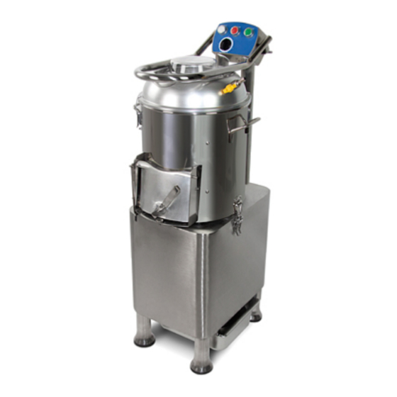
1.2–SAFETY DEVICES INSTALLED ON THE MACHINE The safety devices against risks of electrical nature conform with the norms EN60335-1,EN 55014 and the directives 2006/95/CEE, 2004/108/CEE ,while the mechanical safety devices conform with the directives2006/42 CEE. The machine is equipped with: a starting device consisting of a control card insulated in IP 34,24 Volts, which enables: —turning the machine on and off;... - Page 6 KEY: 1. pushbutton strip 2. hopper 3. cover block hinge 4. pan 5. pan block hinge 6. maintenance door 7. feet 8. structure 9. discharge door 10. cover 11. feeding tap 12. hangdle 13. stand NB: there is the possibility of adding the sieve to the stand to collect waste.
- Page 7 If the details provided in your instruction manual instructions are not followed, the residual risks can occur because of improper use CHAP.2 – TECHNICAL DATA 2.1 – DIMENSIONS, WEIGHT, CHARACTERISTICS... ° — FIG.n Drawings of dimensions TAB.n°1-MEASUREMENTS AND TECHNICAL FEATURES Model HLP-15 HLP-20 220-240V/50HZ Power source 245*360 290*370 C*D*E 410*550*1060 460*590*1100 1490...
- Page 8 CHAP.3 – RECEIVING THE MACHINE ° 3.1--SHIPPING THE MACHINE (see FIG.n The machine leaves our warehouses correctly packaged, such a package consists of: An external box in robust cardboard and a wooden pallet; The machine; This manual; Stand with sieve. d)...
-
Page 9: Machine Placement
must be made aware of the damage within 3 days of the delivery date indicated on the documents, and a detailed report must be written on the damage to the machine. Do not overturn the package!! when the package is being moved make sure that it is firmly held in the four fundamental points(keeping it parallel to the floor). - Page 10 FIG.n°5-Serial number-technical plate Before finally connecting the machine to the three-phase feeder line ,check the direction of ° rotation of the cap by pressing the START pushbutton(see FIG.n 8)then immediately stop it by pressing the STOP pushbutton. The direction of rotation of the cap seen from the discharge outlet must be counterclockwise;if the direction of rotation is not exact, invert two of the three feeding wires in the plug or outlet(see °...
-
Page 11: Electrical Diagrams
4.3- ELECTRICAL DIAGRAMS ° FIG.n 6-1ph electrical diagram Note: SQ1 and SQ2 is the interlocking switch provided on the feeding opening and output opening guards. When open the feeding lid or output door, interlock switch will be on OFF position and cut off the power. -
Page 12: Operational Check
4.4-OPERATIONAL CHECK Before proceeding to testing make sure the upper cover and the discharge door are well-blocked, then check the running of the machine with the following procedure: check that the upper cover and the discharge door are closed well; press the START pushbutton and then the STOP one;... - Page 13 5.2-LOARDING AND WORKING ° THE PRODUCT (see FIG.n NB: The goods to be worked are loaded gradually on the cap from the upper cover when the motor is off. Adhere to the following procedure: load the product from the up per cover, making sure that the discharge door is closed well;...
- Page 14 will stop by releasing the pushbuttons and the discharge door; Avoid making an empty machine turn. HAP.6-ROUTINE CLEANING TTENTION: never put hands inside the moving machine. leaning and maintenance operations are carried out only when the machine is off and the feeding cable is unplugged. .1-GENERALITIES Before cleaning the mac hine the feeding plug must be disconnected...
-
Page 15: Feeding Cable
7.3-FEET The feet could deteriorate with time, thus reducing the stability of the machine. therefore they must be replaced. .4-FEEDING CABLE Periodically check the we ar of the cable and call the “ASSISTANCE CENTER” to replace it. HAP.8-DISMANTLING 8.1-PUTTING I T OUT OF WORK If for some reason it is decided to put th e machine out of work make sure that it cannot be used by... - Page 16 15 15...
- Page 17 Name Name Fixed Guard 203 Bearing Timer Sleeving Arm Spacer O Type Sealing Arm Shaft Belt Wheel Electric Box Limited Pad B-Ribbed Belt Arm Switch Motor Arm Tubing Motor Bracket Glass Lid Transmission Base Switch Box Adjust. Foot Mat Button(White) Supporting Bar Button(Red)...
Need help?
Do you have a question about the HLP-15 and is the answer not in the manual?
Questions and answers