Advertisement
Quick Links
Practical Tips For Getting the Most
Out of Keysight's E36300 Series
Bench Power Supplies
Introduction
Keysight has more than 50 years of experience designing and manufacturing
all types of power products. The next generation of bench power supplies
incorporates your feedback, our engineering knowledge, and design practices to
bring you one of the most versatile bench power product families. This application
note provides practical tips to help you get the most out of Keysight's E36300A
Series bench power supplies. It also introduces you to several convenient features
that are now available in E36311A, E36312A, and E36313A bench power supplies.
Please note that some of features are not available on the E36311A model.
We will cover the following topics:
• Connecting to your bench DC power supply
• Achieving accurate voltage with remote sense
• Measuring current in amps
• Tracking DC outputs
• Enabling high voltage capability
• Enabling high current capability
• Documenting test setups and measurements
• Keeping power supplies secure
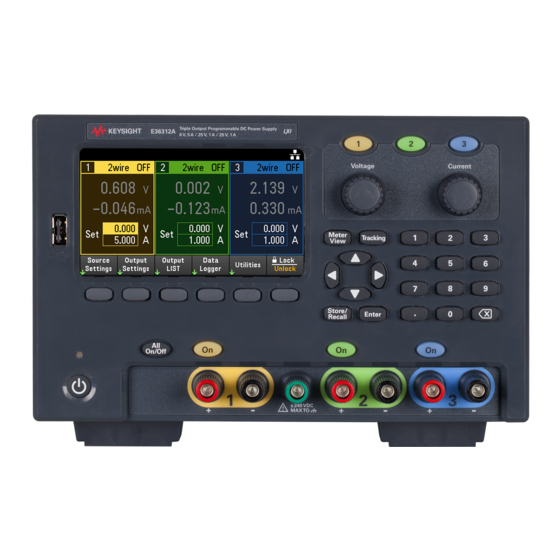
Connecting to your DC bench power supply
To start, connect to the outputs of a E36300 Series DC bench power supply
in two ways – through convenient front panel binding posts (optional recessed
binding posts are available), and through rear panel screw type output connectors.
See Figures 1 and 2.
Find us at www.keysight.com
A P P L I C AT I O N N O T E
The next generation of
bench power supplies
offers new features that
will help you increase
measurement accuracy,
and keep power supplies
consistent and secure.
Page 1
Advertisement

Subscribe to Our Youtube Channel
Related Manuals for Keysight Technologies E36300 Series


Summary of Contents for Keysight Technologies E36300 Series
- Page 1 • Keeping power supplies secure Connecting to your DC bench power supply To start, connect to the outputs of a E36300 Series DC bench power supply in two ways – through convenient front panel binding posts (optional recessed binding posts are available), and through rear panel screw type output connectors.
- Page 2 Tighten screw Locking 12 A screw connector – –S Insert wires Figure 1. Front panel binding posts (max size 14 American Wire Gauge (AWG). A = 20A max current, Twist leads B = 15A max current – Load Figure 2. Rear panel (Channel 1 example) 12A max current (accepts wire sizes from 12 to 30 AWG) Achieving accurate voltage with remote sense...
- Page 3 Wiring tips for remote sense applications We recommend that you use a single twisted pair for the output leads and a separate twisted pair for the sense leads (see Figure 3). Since the sense leads carry very small currents, you may use a lighter gauge wire. Try to keep the sense leads less than 0.5 ohm per wire (a 20 gauge wire works well).
- Page 4 To change the measurement range press Utilities > Test Setup > Lower Range (On/Off). Figure 6. Current measurement using a bench power supply For measurement specifications please see the E36300 Series Data Sheet, literature number 5992-2124EN. Find us at www.keysight.com...
- Page 5 Tracking power supply outputs The E36300A series provides 0 to ± 25 V tracking outputs. In track mode, voltages from Channel 2 and Channel 3 track each other by varying the symmetrical voltages required by operational amps and other circuits that need positive and negative voltages. For example, you can configure your bench power supply for + 5 V and +5 V tracking DC outputs by enabling track mode.
- Page 6 – – Twist leads – Load Figure 8. Wire connections enable higher voltage Enable auto-series operation by pressing Output Settings > Operation Mode > Mode Series. The large display indicates a series connection as shown in Figure 9. Figure 9. Channel 2 controls the series combination Enabling high current capability in two easy steps You may enable higher current capability using the built-in auto-parallel mode with the E36312A or E36313A in two easy steps, with no external connectors or jumpers.
- Page 7 – – Twist leads – Load Figure 10. Set-up that enables higher current capability Enable auto-series operation by pressing Output Settings > Operation Mode > Mode Series. The large display indicates a series connection as shown in Figure 9 Figure 11. Channel 2 is the “master” that controls the parallel combination Documenting your test setup and measurements With the E36300A series bench power supplies, you can easily capture screenshots, save them using the default screenshot filename (screenshot.bmp - date/time stamped), or...
- Page 8 Keysight office. The complete list is available at: www.keysight.com/find/contactus Find us at www.keysight.com Page 8 This information is subject to change without notice. © Keysight Technologies, 2019 - 2021, Published in USA, December 3, 2021, 5992-2472EN...
Need help?
Do you have a question about the E36300 Series and is the answer not in the manual?
Questions and answers