Advertisement
Quick Links
Advertisement

Related Manuals for Keysight Technologies RP7970 Series


Summary of Contents for Keysight Technologies RP7970 Series
- Page 1 Keysight Regenerative Power System RP7970 Series Operating and Service Guide...
- Page 3 Moving Instruments Stacking Instruments Rack Mounting Accessories Outline Diagram for 20 kW Models Single Unit Connections AC Mains Considerations Power Cable Connections Output Connections Single Load Connections Multiple Load Connections Remote Sense Connections Keysight RP7970 Series Operating and Service Guide...
- Page 4 Set the Slew Rate Set the Output Resistance Set the Output Bandwidth Set the Output Turn-On/Turn-Off Mode Enable the Output Parallel Operation Introduction Master/Slave Configuration Front Panel Display Master/Slave Programming Considerations Master/Slave Command Details Troubleshooting Keysight RP7970 Series Operating and Service Guide...
- Page 5 Terminate the Elog Programming the Digital Port Digital Control Port Bi-Directional Digital I/O Digital Input External Trigger I/O Fault Output Inhibit Input Fault/Inhibit System Protection Output Couple Control System-Related Operations Instrument Identification Instrument State Storage Keysight RP7970 Series Operating and Service Guide...
- Page 6 CURRent Subsystem DIGital Subsystem DISPlay Subsystem FETCh Subsystem FORMat Subsystem FUNCtion Command HCOPy Subsystem IEEE-488 Common Commands INITiate Subsystem INSTrument Subsystem LIST Subsystem LXI Subsystem MEASure Subsystem OUTPut Subsystem POWer Query SASimulator Subsystem Keysight RP7970 Series Operating and Service Guide...
- Page 7 Calibration Setups Test Considerations Calibration Procedure Test Record Forms - RPS family 7 Service and Maintenance Introduction Repair Service Available Before Returning the Unit Repackaging for Shipment Cleaning Self-Test Procedure Power-On Self-Test User-Initiated Self-Test Keysight RP7970 Series Operating and Service Guide...
- Page 8 Turn-on after Sanitization Sanitizing an Inoperative Instrument Calibration Switches Accessing the Calibration Switch Switch Functions Battery Replacement Disassembly Electrostatic Discharge (ESD) Precautions Tools Required Cover Disassembly Control Board Disassembly Constellation Board Disassembly Index Keysight RP7970 Series Operating and Service Guide...
- Page 9 No part of this manual may be reproduced in any form or by any means (including electronic storage and retrieval or translation into a foreign language) without prior agreement and written consent from Keysight Technologies as governed by United States and international copyright laws. Keysight Technologies...
- Page 10 Certification Keysight Technologies certifies that this product met its published specifications at time of shipment from the factory. Keysight Technologies further certifies that its calibration measurements are traceable to the United States National Institute of Standards and Technology, to the extent allowed...
- Page 11 This equipment has been conformity assessed for use in business environments. In a residential environment this equipment may cause radio interference. This EMC statement applies to the equipment only for use in business environments. Keysight RP7970 Series Operating and Service Guide...
- Page 12 Failure to comply with these precautions or with specific warnings or instructions elsewhere in this manual violates safety standards of design, manufacture, and intended use of the instrument. Keysight Technologies assumes no liability of the customer’s failure to comply with the requirements.
- Page 13 To prevent electric shock, always disconnect the AC mains before cleaning. Use a dry cloth or one slightly dampened with water to clean the external case parts. Do not use detergent or chemical solvents. Do not attempt to clean internally. Keysight RP7970 Series Operating and Service Guide...
- Page 14 Legal and Safety Information In Case of Damage Instruments that are not functioning correctly, appear damaged or defective should be made inoperative and secured against unintended operation until they can be repaired by qualified service personnel. Keysight RP7970 Series Operating and Service Guide...
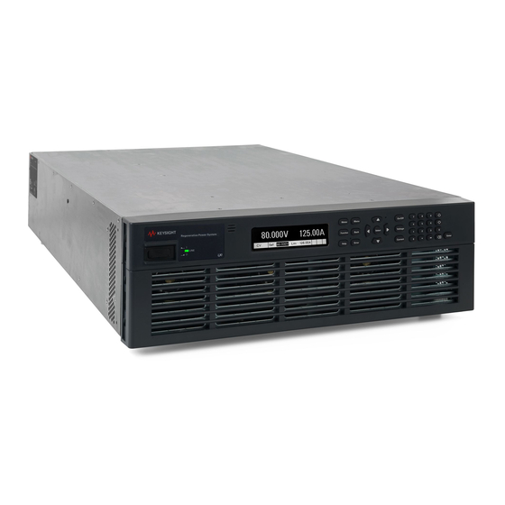
- Page 15 Keysight RP7970 Series Operating and Service Guide Quick Reference Legal and Safety Information Introduction to the Instrument Front Panel Menu Reference Command Quick Reference Model Features and Options Specifications and Characteristics This document includes user, service, and programming information for the Keysight Regenerative Power System (RPS) family.
- Page 16 Solid-state output disconnect switch for fast protection and smooth turn on/off transitions Two-quadrant operation provides current sourcing and sinking capability 20 kW rated models Measurement features 5.12 microsecond sample rate Real-time power measurements Amp-hour & Watt-hour measurement Digitized measurement capability Keysight RP7970 Series Operating and Service Guide...
- Page 17 2. Display - Turns off after 1 hour of inactivity. Press any key to restore the display. 3. System keys - Select metering function. Access front panel command, help, and error menus. Keysight RP7970 Series Operating and Service Guide...
- Page 18 7. LAN - 10/100/1000 Base-T Left LED indicates activity. Right LED indicates link integrity. 8. Master/slave - Master/slave connectors - for grouping paralleled units. 9. Termination switches - Specifies master/slave termination types. 10. Safety disconnect - Not available for use. Keysight RP7970 Series Operating and Service Guide...
- Page 19 Err = an error has occurred (press Error key to display error message) Lan = the LAN is connected and has been configured IO = there is activity on one of the remote interfaces Keysight RP7970 Series Operating and Service Guide...
- Page 20 The Backspace key deletes digits as it backspaces over them. The Enter key enters a value. If you exit a field without pressing the Enter key, the value is ignored. Press the Help key to get context sensitive help. Keysight RP7970 Series Operating and Service Guide...
- Page 21 Mode Selects voltage and current transient modes Step Configures voltage or current steps and trigger signals List Pace Specifies Dwell or Trigger paced list Repeat Specifies number of list repetitions, or continuous list Keysight RP7970 Series Operating and Service Guide...
- Page 22 DigPort Pins Configures the individual digital port pins Data Reads/writes data to the digital port Groups Function Specifies the master or slave function Master Discovers and connects the master to the slave units Keysight RP7970 Series Operating and Service Guide...
- Page 23 Enables/disables USB, GPIB, and LAN services Sanitize Performs NISPOM secure erase of all user data Update Password protected firmware update Password Changes the admin password About Displays model, options, serial number, and firmware version Keysight RP7970 Series Operating and Service Guide...
- Page 24 Returns the Low level of a pulse waveform. :MAXimum? Returns the maximum value :MINimum? Returns the minimum value :POWer [:DC]? Returns the averaged measurement. :MAXimum? Returns the maximum value :MINimum? Returns the minimum value Keysight RP7970 Series Operating and Service Guide...
- Page 25 Saves the instrument state to one of ten non-volatile memory locations. *SRE <value> Service request enable command and query. *STB? Status byte query. *TRG Trigger command. *TST? Self-test query. *WAI Pauses additional command processing until all pending operations are complete. Keysight RP7970 Series Operating and Service Guide...
- Page 26 Takes a measurement; returns the maximum power. :MINimum? Takes a measurement; returns the minimum power. :VOLTage [:DC]? Takes a measurement; returns the averaged voltage. :ACDC? Takes a measurement; returns the RMS voltage (AC + DC). Keysight RP7970 Series Operating and Service Guide...
- Page 27 Resets the amp-hour or watt-hour measurement to zero. :ELOG :FUNCtion :CURRent 0|OFF|1|ON Enables/disables external current logging. :MINMax 0|OFF|1|ON Enables/disables external min/max current logging. :VOLTage 0|OFF|1|ON Enables/disables external voltage logging. :MINMax 0|OFF|1|ON Enables/disables external min/max voltage logging. Keysight RP7970 Series Operating and Service Guide...
- Page 28 [SOURce:] CURRent [:LEVel] [:IMMediate] [:AMPLitude] <value> Sets the output current when in current priority mode. :TRIGgered [:AMPLitude] <value> Sets the triggered output current. :BWIDth :LEVel 0, <value> Sets the compensation frequency. :LIMit [:POSitive] Keysight RP7970 Series Operating and Service Guide...
- Page 29 Specifies the dwell time for each list step. :POINts? Returns the number of dwell points. :STEP ONCE|AUTO Specifies trigger or dwell pacing. :TERMinate :LAST 0|OFF|1|ON Determines the output value when the list terminates. :TOUTput :BOSTep Keysight RP7970 Series Operating and Service Guide...
- Page 30 Returns the number of current points in the current table. :VOLTage [:AMPLitude] <value>{,<value>} Programs a list of voltage points in Table mode. :POINts? Returns the number of current points in the voltage table. Keysight RP7970 Series Operating and Service Guide...
- Page 31 Queries the operation condition register. :ENABle <value> Sets the operation enable register. :NTRansiton <value> Sets the Negative transition filter. :PTRansiton <value> Sets the Positive transition filter. :PRESet Presets all Enable, PTR, and NTR registers. Keysight RP7970 Series Operating and Service Guide...
- Page 32 :SOURce <source> Selects the trigger source for arbitrary waveforms: BUS |EXTernal |IMMediate |PIN<1-7> :ELOG [:IMMediate] Generates an immediate trigger. :SOURce <source> Selects the trigger source for external data logging: BUS |EXTernal |IMMediate |PIN<1-7> :TRANsient Keysight RP7970 Series Operating and Service Guide...
- Page 33 1 Quick Reference [:IMMediate] Generates an immediate trigger. :SOURce <source> Selects the transient trigger source: BUS |EXTernal |IMMediate |PIN<1-7> Keysight RP7970 Series Operating and Service Guide...
- Page 34 Basic rail kit for system II Keysight instrument racks Keysight Advanced/multi-input PV inverter test software for up to 12 instruments DG9000 Keysight Advanced sourcing and measurement functionality for a single or up to four instruments BV9201B/BV9200B Keysight RP7970 Series Operating and Service Guide...
- Page 35 5 Time to recover to within the settling band following a step change from 40% to 90% and 90% to 40% of full load at Comp 0, with a 40 μs current rise and fall time Keysight RP7970 Series Operating and Service Guide...
- Page 36 Output on delay time 5 Voltage priority - high impedance: 8.1 ms 8.1 ms Voltage priority - low impedance: 8.1 ms 8.1 ms Current priority: 7.1 ms 7.1 ms Maximum load inductance: 6 185 µH 740 µH Keysight RP7970 Series Operating and Service Guide...
- Page 37 Acoustic statement Acoustic noise emission LpA 80.92 dB at Operator position: 1 (European Machinery Directive) LpA 75.57 dB at Bystander position LpA 62.04 at Idle fan speed Normal operation mode per ISO 7779 Keysight RP7970 Series Operating and Service Guide...
- Page 38 1 A sound pressure level of 80 dBA above a reference sound pressure of 20 μPa is at present regarded by man authorities as the threshold at which a hazard may be caused. Special means, such as the use of protective earpieces, can make a higher level non-hazardous to an operator. Keysight RP7970 Series Operating and Service Guide...
- Page 39 Source/Sink Efficiency (1 kV units, 380V=lowline, 480V=highline) Power Factor (2 kV units, 380V=lowline, 480V=highline) Power Factor (1 kV units, 380V=lowline, 480V=highline) Total Harmonic Distortion (2 kV units, 380V=lowline, 480V=highline) Total Harmonic Distortion (1 kV units, 380V=lowline, 480V=highline) Keysight RP7970 Series Operating and Service Guide...
- Page 40 Output Impedance Amplitude (2 kV units) Output Impedance Phase (2 kV units) Voltage Priority Voltage Priority Current Priority Current Priority Output Impedance Amplitude (1 kV units) Output Impedance Phase (1 kV units) Voltage Priority Voltage Priority Keysight RP7970 Series Operating and Service Guide...
- Page 41 Inductive Load Boundary (2 kV units) Inductive Load Boundary (1 kV units) 1. The output is stable in this region 2. The output may overshoot in this region 3. The output may be unstable in this region Keysight RP7970 Series Operating and Service Guide...
- Page 42 Capacitive Load Boundary (2 kV units) Capacitive Load Boundary (1 kV units) 1. The output is stable in this region 2. The output may overshoot in this region 3. The output may be unstable in this region Keysight RP7970 Series Operating and Service Guide...
- Page 43 DUT is a low AC impedance. The characteristic is valid when operating above 10% of the rated output of the unit. Programming Bandwidth Amplitude (2 kV & 1 kV units) Programming Bandwidth Phase (2 kV & 1 kV units) Keysight RP7970 Series Operating and Service Guide...
- Page 44 The following graph plots the maximum permissible output peak-to-peak voltage that can safely be generated by the arbitrary waveform system at a specific frequency. The values are normalized in terms of full scale peak to peak voltage; therefore all models are represented. Keysight RP7970 Series Operating and Service Guide...
- Page 45 C. The unit will not operate in this region. This region is bounded by the sinking resistance limit. The border lines between A, B, and C are approximate. Keysight RP7970 Series Operating and Service Guide...
- Page 47 Keysight RP7970 Series Operating and Service Guide Installing the Instrument Before Installation or Use Single Unit Connections Multiple Unit Connections Interface Connections Heavy Weight Danger to hands and feet. To avoid personal injury and damage to the instrument, always use a sturdy cart or other suitable device to move the instrument.
- Page 48 2,000 VDC! Ensure that all instrument connections, load wiring, load and sense connections are insulated using high-voltage wire. Always attach the safety cover provided, so that no accidental contact with lethal voltages can occur. Keysight RP7970 Series Operating and Service Guide...
- Page 49 Rack mount kit for Keysight racks or similar design. Includes all necessary hard- ware to allow units to be mounted in a 19-inch EIA rack cabinet. Always observe caution when extending the unit from the rack to avoid tipping. Keysight RP7970 Series Operating and Service Guide...
- Page 50 2 Installing the Instrument Outline Diagram for 20 kW Models Keysight RP7970 Series Operating and Service Guide...
- Page 51 A gas-discharge tube is installed between the neutral connection and chassis ground. Several internal protection functions are used to safeguard the instrument against abnormal line conditions while also preventing AC mains islanding. The following conditions cause the instrument to shut down: Keysight RP7970 Series Operating and Service Guide...
- Page 52 20 kW, 380-480 VAC 36 A 36 A 36 A The cable cross-section must be suitable for the maximum input current of the instrument. The ground cable must have the same cross-section as the phase cable. Keysight RP7970 Series Operating and Service Guide...
- Page 53 For 10 AWG: WAGO 216-288 (Refer to manufacturer for details.) Connect the ground wire to the chassis stud located below the AC connector. The stud diameter is M5. Torque the M5 combination nut to 20 in-lbs. Keysight RP7970 Series Operating and Service Guide...
- Page 54 Paralleled load wires may be required for larger-ampacity models. The following table lists the characteristics of AWG (American Wire Gauge) copper wire. Keysight RP7970 Series Operating and Service Guide...
- Page 55 Tightening torque for the 8.8 mm opening cannot exceed 10.8 Nm (8 lb-ft). Tightening torque for the 5.5 mm opening cannot exceed 4.8 Nm (3.5 lb-ft). Keysight RP7970 Series Operating and Service Guide...
- Page 56 If you are using local sensing and are connecting multiple loads to one output, connect each load to the output terminals using separate connecting wires as shown in the following figure. This minimizes mutual coupling effects and takes full advantage of the power supply's low output impedance. Keep Keysight RP7970 Series Operating and Service Guide...
- Page 57 Connect the unit for remote sensing by first removing the local sense cable between the sense and load terminals. Then make your sense and load connections as shown in the following figure. Note that the two center terminals of the sense connector are not used. Keysight RP7970 Series Operating and Service Guide...
- Page 58 If the remote sense wires open during normal CV operation (with output current present), the change in output voltage at the load will depend on the load current and the load wire resistances involved. Keysight RP7970 Series Operating and Service Guide...
- Page 59 By setting the proper voltage slew rate when using an external capacitor, it may be possible to prevent mode crossover into constant current. Use the following formula to estimate the additional programming response time: Keysight RP7970 Series Operating and Service Guide...
- Page 60 DUT is of a resistive or high impedance nature and may have some local bypass capacitance near its own terminals. Remote sensing at the DUT terminals is recommended if accurate DC voltage regulation is required. RP797xA Keysight RP7970 Series Operating and Service Guide...
- Page 61 For operation of the units in current priority mode, the setup typically resembles that in the following figure where the DUT is of a low impedance or voltage source nature. Sense lead measurements are still utilized to detect over/under voltage protection events and when cross-over into CV operation occurs. Keysight RP7970 Series Operating and Service Guide...
- Page 62 DUT. After a short delay, the excessive current flow will cause over-current protection to engage - thereby disabling the output of the unit. Keysight RP7970 Series Operating and Service Guide...
- Page 63 Exposed bus bar surfaces must either be enclosed in a cabinet or insulated so that no accidental contact with lethal voltages can occur. Keysight RP7970 Series Operating and Service Guide...
- Page 64 2,000 VDC! Ensure that all instrument connections, load wiring, load and sense connections are insulated using high-voltage wire. Always attach the safety cover provided, so that no accidental contact with lethal voltages can occur. Keysight RP7970 Series Operating and Service Guide...
- Page 65 One reason is that exceeding the maximum float voltages ratings given in the characteristics tables is extremely dangerous and it is impossible to guarantee safe voltage balance when using bidirectional instruments in series. Keysight RP7970 Series Operating and Service Guide...
- Page 66 3. You can now use Interactive IO within the Connection Expert to communicate with your instru- ment, or you can program your instrument using the various programming environments. USB Connections The following figure illustrates a typical USB interface system. Keysight RP7970 Series Operating and Service Guide...
- Page 67 A private LAN is a network in which LAN-enabled instruments and computers are directly connected, and not connected to a site LAN. They are typically small, with no centrally-managed resources. The following figure illustrates a typical private LAN system. Keysight RP7970 Series Operating and Service Guide...
- Page 68 4. Output Couple configurable pins 5. Digital IO-configurable pins 6. Signal common Information on using the digital port is found under Programming the Digital Port. The electrical characteristics are described in the Common Characteristics tables. Keysight RP7970 Series Operating and Service Guide...
- Page 69 2. Connect the LAN, USB, GPIB cable, and digital IO wires (GPIB shown) to the appropriate rear panel connector. 3. Insert the cover tabs into the flange. Attach the ESD cover to the back of the unit using the two cap- tive cover screws. Keysight RP7970 Series Operating and Service Guide...
- Page 71 Keysight RP7970 Series Operating and Service Guide Getting Started Using the Front Panel Remote Interface Configuration...
- Page 72 AC power connected, and if it is green, the instrument is on. If a self-test error occurs, a message is displayed on the front panel. For other self- test errors, see Service and Maintenance for instructions on returning the instrument for service. Keysight RP7970 Series Operating and Service Guide...
- Page 73 Enter the desired setting using the numeric keypad. Then press Enter. If you make a mistake, either use the backspace key to delete the number, press Back to back out of the menu, or press Meter to return to meter mode. Keysight RP7970 Series Operating and Service Guide...
- Page 74 Enter. If you make a mistake, either use the backspace key to delete the number, press Back to back out of the menu, or press Meter to return to meter mode. Keysight RP7970 Series Operating and Service Guide...
- Page 75 Press the right arrow navigation key > to traverse the menu until the Protect command is highlighted. Press the Select key to access the Protect commands. Since the OVP command is already highlighted, press the Select key to access the OVP dialog. Keysight RP7970 Series Operating and Service Guide...
- Page 76 Press the Help key at the lowest menu level to display help information about the menu function controls. Whenever a limit is exceeded or any other invalid configuration is found, the instrument will display a message, including Error code information. Press Meter or Back to exit Help. Keysight RP7970 Series Operating and Service Guide...
- Page 77 This setting is non-volatile; it will not be changed by power cycling or *RST. Use the front panel menu to change the GPIB address: Keysight RP7970 Series Operating and Service Guide...
- Page 78 You can also reset the LAN to the as-shipped (default) settings. This returns ALL LAN settings to the as-shipped values and restarts networking. All default LAN settings are listed under Non-volatile Settings. Keysight RP7970 Series Operating and Service Guide...
- Page 79 "192.168.020.011" is actually equivalent to decimal "192.168.16.9" because ".020" is interpreted as "16" expressed in octal, and ".011" as "9". To avoid confusion, use only decimal values from 0 to 255, with no leading zeros. Keysight RP7970 Series Operating and Service Guide...
- Page 80 "192.168.020.011" is actually equivalent to decimal "192.168.16.9" because ".020" is interpreted as "16" expressed in octal, and ".011" as "9". To avoid confusion, use only decimal values from 0 to 255, with no leading zeros. Keysight RP7970 Series Operating and Service Guide...
- Page 81 The built-in Web interface only operates over the LAN. A Web browser is required to use the Web Interface. The Web interface is enabled when shipped. To launch the Web interface: Keysight RP7970 Series Operating and Service Guide...
- Page 82 IP address, and 5024 is the instrument’s telnet port. You should get a Telnet session box with a title indicating that you are connected to the power supply. Type the SCPI commands at the prompt. Keysight RP7970 Series Operating and Service Guide...
- Page 83 Not available Enable or disable the interfaces by checking or unchecking the following items: Enable LAN, Enable GPIB, and Enable USB If you cannot access the Admin menu, it may be password protected. Keysight RP7970 Series Operating and Service Guide...
- Page 85 Keysight RP7970 Series Operating and Service Guide Using the Regenerative Power System Programming the Output Parallel Operation Current Sinking Operation Programming Output Protection Programming Output Transients Sequencing the Output Making Measurements External Data Logging Programming the Digital Port System-Related Operations...
- Page 86 To specify current or voltage priority mode: FUNC CURR|VOLT Select Voltage or Current priority. Then press Select. When switching between modes, the output is turned off and the output settings revert to their power-on or RST values. Keysight RP7970 Series Operating and Service Guide...
- Page 87 Front Panel Menu Reference SCPI Command Press the Current key. To set the positive current limit: CURR:LIM 12 Specify a positive or negative Current limit. To set the negative current limit: CURR:LIM:NEG -3 Then press Select. Keysight RP7970 Series Operating and Service Guide...
- Page 88 Front Panel Menu Reference SCPI Command Select Output\Advanced\Resistance. To select a resistance of 0.5 ohms: VOLT:RES 0.5 Specify an Output Resistance value. Then check the Enable box. Then press Select. To enable output resistance: VOLT:RES:STAT ON Keysight RP7970 Series Operating and Service Guide...
- Page 89 0.1%-100% of rating 100 kHz 0.5 ms 2.5 ms 2 Slow no load, 0.1%-100% of rating 100 kHz 8 ms 90 ms The following table describes the CV small signal bandwidth characteristics for all models Keysight RP7970 Series Operating and Service Guide...
- Page 90 The turn-on/turn-off setting only applies when the unit is operating in voltage priority mode. In current priority mode, the turn-on/turn-off behavior is set to High impedance. The voltage priority turn-on and turn-off behavior can be set to either high or low impedance mode. Keysight RP7970 Series Operating and Service Guide...
- Page 91 During a 1-cycle AC line dropout the unit may reboot. The output will remain off after reboot until the operator reinstates the previous settings, either by the front panel controls or using a computer program. This behavior is consistent with safe operating procedures. Keysight RP7970 Series Operating and Service Guide...
- Page 92 Configure one unit as the master Configure the other units as slaves with unique bus addresses Select the connection mode and auto-connect delay time Perform a one-time discovery on the master - it saves the master/slave configuration Keysight RP7970 Series Operating and Service Guide...
- Page 93 After initial discovery, the discovery process does not need to be run again unless the master/slave configuration changes. Front Panel Menu Reference SCPI Command Select System\Group\Discover To discover the slave units: In the dialog box select Discover to discover all slave INST:GRO:MAST:DISC units. Then press Select. Keysight RP7970 Series Operating and Service Guide...
- Page 94 In current priority mode, set the output current of the master unit to the desired value. Set the voltage limit to a higher value than the expected operating voltage of the unit. Keysight RP7970 Series Operating and Service Guide...
- Page 95 When using the Fault Inhibit functions on the rear panel digital connector, connect the Fault/Inhibit pins only on the master unit. You do not need to connect the Fault/Inhibit pins of the slave units. Keysight RP7970 Series Operating and Service Guide...
- Page 96 MSP. Check that the master/slave CAT6A cables are installed correctly. This can also occur when changing the master slave configuration. Always set the master unit to None when changing master/slave configurations. Keysight RP7970 Series Operating and Service Guide...
- Page 97 AC mains. Refer to AC Mains Considerations for additional information. Keysight RP7970 Series Operating and Service Guide...
- Page 98 If an internal temperature exceeds the pre-defined limit, the unit goes into a latched protection state. The OUTP:PROT:TEMP:MARG? query can be used to return the margin remaining between the temperature sensor reading and the over-temperature trip level. OT Keysight RP7970 Series Operating and Service Guide...
- Page 99 1 volt plus 10% of rating above the user-programmed positive OVP level. If the output voltage exceeds this level the unit goes into a latched protection state. LOV is always enabled. LOV- Negative local over-voltage protection is not available on two-quadrant models. Keysight RP7970 Series Operating and Service Guide...
- Page 100 Arb output change. It also includes voltage and current slew changes, so that the timer is restarted throughout the entire slew time. Current limit - starts the over-current delay timer by any transition of the output into current limit. Keysight RP7970 Series Operating and Service Guide...
- Page 101 The Prot bit in the status questionable register as well as the Prot indicator on the front panel will be set. A watchdog protect can be cleared as described under Clear Output Protection. Keysight RP7970 Series Operating and Service Guide...
- Page 102 Enter a value in the UVP level box. Then check Enable UVP To enable low-voltage protection: VOLT:PROT:LOW:STAT ON Enter a value in the UVP Delay box. Then press Select. To specify a protection delay of 5 seconds: VOLT:PROT:LOW:DEL 5 Keysight RP7970 Series Operating and Service Guide...
- Page 103 Then, clear the protection function as follows: Front Panel Menu Reference SCPI Command Select Protect\Clear To clear a protection fault: OUTP:PROT:CLE Select Clear. The output is re-enabled once the output protection function is cleared. Keysight RP7970 Series Operating and Service Guide...
- Page 104 The transient trigger process is illustrated below. This applies to all transient types. The arrows on the right are specific to List transients. For an overview of the trigger system, refer to Trigger Overview. Keysight RP7970 Series Operating and Service Guide...
- Page 105 Triggers the transient as soon as it is INITiated. Pin<1-7> Selects a specific pin<n> that is configured as a Trigger Input on the digital control port. Use the following commands to select a trigger source: Keysight RP7970 Series Operating and Service Guide...
- Page 106 TRIG:TRAN Select Trigger to generate an immediate trigger signal regardless of the trigger source setting. Alternatively, if the trigger source is BUS, you can also program a *TRG or an IEEE-488 <get> command. Keysight RP7970 Series Operating and Service Guide...
- Page 107 In the front panel menu, you can only program the step level based on the priority mode that you are operating in - voltage or current priority. Keysight RP7970 Series Operating and Service Guide...
- Page 108 With a trigger-paced list, triggers that are received during the dwell period are ignored. You can set the list dwell time to zero ensure that no triggers are lost. Keysight RP7970 Series Operating and Service Guide...
- Page 109 To generate the voltage list shown in the figure, a list may include the following values: 9, 0, 6, 0, 3, 0: Keysight RP7970 Series Operating and Service Guide...
- Page 110 The number of dwell steps must equal the number of voltage steps. If a dwell list has only one value, that value will be applied to all steps in the list. Keysight RP7970 Series Operating and Service Guide...
- Page 111 Sending the INFinity parameter in the SCPI command makes the list repeat indefinitely. Front Panel Menu Reference SCPI Command Select Transient\List\Repeat. To program the list to repeat twice: LIST:COUN 2 Enter the number of list repetitions (2) and press Select. Keysight RP7970 Series Operating and Service Guide...
- Page 112 To enable the transient function, use: VOLT:MODE ARB In voltage priority mode select Voltage mode. In current priority mode select Current mode. In the CURR:MODE ARB dropdown list, select Arb. Then press Select. Keysight RP7970 Series Operating and Service Guide...
- Page 113 To return the output to the pre-Arb state: ARB:TERM:LAST OFF Select either Return to Start, or Stop at Last Step and press Select. To keep the output at the Arb end point: ARB:TERM:LAST ON Keysight RP7970 Series Operating and Service Guide...
- Page 114 OnCouple and OffCouple signals to enable and disable the output. These signals provide an additional level of control when sequencing the output on individual and multiple units. The following figure illustrates the programming path when using the OnCouple and OffCouple signals to control the output. Keysight RP7970 Series Operating and Service Guide...
- Page 115 Front Panel Menu Reference SCPI Command Select Output\Sequence\Couple. Program a turn-on delay: OUTP:DEL:RISE .02 Specify the Turn-on delay in seconds. Repeat for each instrument. Repeat for each additional unit. Keysight RP7970 Series Operating and Service Guide...
- Page 116 Enter the delay offset value of the Use the delay offset of the slowest unit to specify slowest unit in the Delay offset field in milliseconds. Then the common delay offset press Select. OUTP:COUP:DOFF <value> Keysight RP7970 Series Operating and Service Guide...
- Page 117 If you wish to program a voltage turn-off slew rate, you must set the slew rate and program the output voltage to zero before you send the output off command. Keysight RP7970 Series Operating and Service Guide...
- Page 118 When a protection event is detected, the power supply immediately opens the solid-state output switch. This typically takes less than 50 μs following the initial detection. Turn-On/Turn-Off Flowchart Keysight RP7970 Series Operating and Service Guide...
- Page 119 To set the number of power line cycles to 10: SENS:SWE:NPLC 10 Enter the number of power line cycles in the NPLC field. Then press Select. The AC line frequency is detected automatically for SENSe:SWEep:NPLC. Keysight RP7970 Series Operating and Service Guide...
- Page 120 To return Amp-hours and Watt-hours measurements: Front Panel Menu Reference SCPI Command Select Measure\AHWH. To return the Amp-hours and Watt hours: FETC:AHO? Displays the accumulated Amp-hours and Watt-hours. FETC:WHO? To reset the Amp-hours and Watt-hours measurements: Keysight RP7970 Series Operating and Service Guide...
- Page 121 Front Panel Menu Reference SCPI Command Not available To measure RMS voltage & current: MEAS:VOLT:ACDC? MEAS:CURR:ACDC? To measure the high level of a pulse: MEAS:VOLT:HIGH? MEAS:CURR:HIGH? To measure the low level of a pulse: MEAS:VOLT:LOW? MEAS:CURR:LOW? Keysight RP7970 Series Operating and Service Guide...
- Page 122 The NPLC command automatically increases the number of points to maintain the shortest possible time interval. If the maximum number of points for that time interval is reached, it increases the time interval. Keysight RP7970 Series Operating and Service Guide...
- Page 123 The measurement system lets you capture data before, after, or at the trigger signal. As shown in the following figure, you can move the block of data being read into the acquisition buffer with reference to the trigger. This allows pre- or post-trigger data sampling. Keysight RP7970 Series Operating and Service Guide...
- Page 124 Selects the unit’s transient system. You must also set up the transient system to generate a trigger out signal. Programming Output Transients. Voltage Selects an output voltage level. Use the following commands to select a trigger source: Keysight RP7970 Series Operating and Service Guide...
- Page 125 Front Panel Menu Reference SCPI Command Not available To generate a measurement trigger: TRIG:ACQ Alternatively, if the trigger source is BUS, you can also program a *TRG or an IEEE-488 <get> command. Keysight RP7970 Series Operating and Service Guide...
- Page 126 MEAS_active bit after the measurement is initiated to determine when the measurement is complete and then send the FETCh query. You can test the MEAS_active bit in the operation status register to know when the trigger system has returned to the idle state. Keysight RP7970 Series Operating and Service Guide...
- Page 127 To return DC voltage or current calculated after the trigger indcies: FETC:VOLT? [<start_index>, <points>] FETC:CURR? [<start_index>, <points>] To return instantaneous voltage or current data after the trigger indices: FETC:ARR:VOLT? [<start_index>, <points>] FETC:ARR:CURR? [<start_index>, <points>] Keysight RP7970 Series Operating and Service Guide...
- Page 128 The following commands select a measurement function: Front Panel Menu Reference SCPI Command Not available To enable voltage or current measurements: SENS:ELOG:FUNC:VOLT ON SENS:ELOG:FUNC:CURR ON To enable min/max measurements: SENS:ELOG:FUNC:VOLT:MINM ON SENS:ELOG:FUNC:CURR:MINM ON Keysight RP7970 Series Operating and Service Guide...
- Page 129 Triggers the measurement as soon as it is INITiated. Pin<1-7> Selects a specific pin<n> that is configured as a Trigger Input on the digital control port. Use the following commands to select one of the available trigger sources: Keysight RP7970 Series Operating and Service Guide...
- Page 130 Elog sensing. If all functions are enabled, then one record will contain the following data in the specified order: Current average Current minimum Current maximum Voltage average Voltage minimum Voltage maximum Keysight RP7970 Series Operating and Service Guide...
- Page 131 REAL data is returned as a definite length block, with the byte order specified by the FORMat:BORDer command. Terminate the Elog Front Panel Menu Reference SCPI Command Not available To abort the Elog: ABOR:ELOG Keysight RP7970 Series Operating and Service Guide...
- Page 132 A trigger input pin can be selected as the source for measurement and transient trigger signals. See TRIGger- :ACQuire:SOURce TRIGger:TRANsient:SOURce TOUTput A trigger output pin will generate output triggers from any subsystem that has been configured to output trigger signals. Common Applies only to pin 8. Connected to ground. Keysight RP7970 Series Operating and Service Guide...
- Page 133 In the Polarity field, select either Positive or Negative. To configure pins 1 through 7 as “0000111”: To send data to the pins, select DIG:OUTP:DATA 7 System\IO\DigPort\Data. Select the Data Out field and enter the binary word. Keysight RP7970 Series Operating and Service Guide...
- Page 134 In the Function field, select either the Trig In or Trig Out DIG:PIN2:FUNC TINP function. To select the pin polarity: In the Polarity field, select either Positive or Negative. DIG:PIN1:POL POS DIG:PIN2:POL POS Keysight RP7970 Series Operating and Service Guide...
- Page 135 In the Polarity field, select either Positive or Negative. DIG:PIN3:POL POS Select Protect\Inhibit. To specify the Inhibit mode: Select either Latching or Live. OUTP:INH:MODE LATC OUTP:INH:MODE LIVE To disable the Inhibit signal, select Off. OUTP:INH:MODE OFF Keysight RP7970 Series Operating and Service Guide...
- Page 136 2. Set the delay offset of each individual unit to match the longest delay offset of the group. 3. Connect and configure the digital connector pins of the sequenced units as shown below. Keysight RP7970 Series Operating and Service Guide...
- Page 137 Repeat commands for units 2 and 3. Once configured and enabled, turning the output on or off on any coupled unit will cause all coupled units to turn on or off according to their user-programmed delays. Keysight RP7970 Series Operating and Service Guide...
- Page 138 However, you can configure the power supply to use the settings you have stored in memory location 0 at power-on. Front Panel Menu Reference SCPI Command Select States\PowerOn. OUTP:PON:STAT RCL0 Select Recall State 0. Then press Select. Keysight RP7970 Series Operating and Service Guide...
- Page 139 This parameter is saved in non-volatile memory. Therefore, the front panel remains locked even after AC power is cycled. Front Panel Menu Reference SCPI Command Select System\Preferences\Lock Not available In the dialog box, enter the password to unlock the front panel. Then select Lock. Keysight RP7970 Series Operating and Service Guide...
- Page 140 Enter the date in the Month, Day and Year fields. Enter the time in the Hour, Minute, and Second fields. To set the time: Press Select to set the date and time. SYSTem:TIME 20,30,0 Keysight RP7970 Series Operating and Service Guide...
- Page 141 The output is turned off when switching between Fixed mode and Curve or Table modes. When switching between Fixed and Curve/Table modes, all settings will be returned to their *RST values. When switching between Curve and Table modes, solar array settings will be preserved. Keysight RP7970 Series Operating and Service Guide...
- Page 142 1024 I-V points per table. Table values are not saved as part of the instrument state. You can load up to two tables into instrument memory. The table lists must satisfy the following requirements. Keysight RP7970 Series Operating and Service Guide...
- Page 143 To use a table once it has been loaded into memory, it must be transferred Into the SAS system location. The SAS:TABLe:ACTivate command moves (updates) the data into the SAS system and selects the table for the power stage. Keysight RP7970 Series Operating and Service Guide...
- Page 144 You can also use this command to switch between the two tables in the SAS system location without turning off the output. Front Panel Menu Reference SCPI Command Not available To select and run table 1 in the SAS system: SAS:TABL:SEL 1 to switch and run table 2 SAS:TABL:SEL 2 Keysight RP7970 Series Operating and Service Guide...
- Page 145 CURRent[:LEVel] all CURR[:LEV] commands CURRent:LIMit all CURR:LIM commands CURRent:MODE STEP|LIST|ARB all CURR:MODE commands except FIXed CURRent:PROTection:STATe Enable current protection state CURRent:SLEW Current slew setting FUNCtion CURR|VOLT Priority mode setting OUTput[:STATe]:TMODe Output turn-on mode Keysight RP7970 Series Operating and Service Guide...
- Page 146 Space Curve Shape The following equations describe the solar array simulator space model using the parameters Rs, N, and a, which are defined as functions of the four input parameters Voc, Vmp, Isc, and Imp. Keysight RP7970 Series Operating and Service Guide...
- Page 147 Performance Test Protocol, “Performance Test Protocol for Evaluating Inverters Used in Grid- Connected Photovoltaic Systems”. To establish this equivalence, the following variable substitutions must be made: EN 50530 Sandia I sc *C 1 C aq Keysight RP7970 Series Operating and Service Guide...
- Page 148 Instead, the power supply will now regulate the output current at its current limit setting. A LIM+ (positive current Keysight RP7970 Series Operating and Service Guide...
- Page 149 A CC (constant current) status indicates that the output current is being regulated and the output voltage is within its limit settings. Keysight RP7970 Series Operating and Service Guide...
- Page 150 For additional information on priority mode operation during output turn-on/turn- off, refer to Turn-On Turn-Off Behavior. Keysight RP7970 Series Operating and Service Guide...
- Page 151 Keysight RP7970 Series Operating and Service Guide SCPI Programming Reference Related Software SCPI Introduction Commands by Subsystem Status Tutorial Trigger Tutorial Reset State SCPI Error Messages Compatibility Commands...
- Page 152 Keysight Developer Network at www.keysight.com/find/adn. Interface Documentation For detailed information about interface connections, refer to the Keysight Technologies USB/LAN/GPIB Interfaces Connectivity Guide, included with the Keysight IO Libraries Suite. Or you can download the guide from the Web at www.keysight.com/find/connectivity.
- Page 153 A portion of the OUTPut subsystem is shown below to illustrate the tree system. Note that some [optional] commands have been included for clarity. OUTPut [:STATe] OFF|0|ON|1 :DELay :FALL <value>|MIN|MAX :RISE <value>|MIN|MAX :INHibit :MODE LATChing|LIVE|OFF Keysight RP7970 Series Operating and Service Guide...
- Page 154 In the following example, the optional startindex and points parameters must be separated with a comma. Note the space between CURRent? and the first parameter. FETCh:CURRent? [< start_index >, < points >] Keysight RP7970 Series Operating and Service Guide...
- Page 155 A vertical bar ( | ) separates multiple parameter choices for a given command string. For example, LATChing|LIVE|OFF in the OUTPut:INHibit command indicates that you can specify "LATChing", "LIVE", or "OFF". The bar is not sent with the command string. Keysight RP7970 Series Operating and Service Guide...
- Page 156 "OFF" or "0". For a true condition, the instrument will accept "ON" or "1". When you query a Boolean setting, the instrument will always return "0" or "1". The following command requires a Boolean parameter: DISPlay OFF|0|ON|1 Keysight RP7970 Series Operating and Service Guide...
- Page 157 (like the output voltage to finish changing or output state completing turn on). Query command times apply from when the command was sent to the instrument until the response is received. Keysight RP7970 Series Operating and Service Guide...
- Page 158 Return 25 k point fetch: FETC:VOLT? 5.07 ms 7.01 ms Return 25 k point ASCII array fetch: FETC:ARR:VOLT? 4009.5 ms 1010.8 ms Return 25 k point binary array fetch: FETC:ARR:VOLT? 694.25 ms 30.39 ms Keysight RP7970 Series Operating and Service Guide...
- Page 159 5 SCPI Programming Reference Commands by Subsystem ABORt CALibrate DISPlay FETCh FORMat HCOPy IEEE-488 Common INITiate INSTrument MEASure OUTPut SENSe [SOURce:] CURRent DIGital FUNCtion LIST POWer SASimulator (photovoltaic) STEP VOLTage STATus SYSTem TRIGger Keysight RP7970 Series Operating and Service Guide...
- Page 160 Operation Status registers. Note that this command does not turn off continuous triggers if INITiate:CONTinuous:TRANsient ON has been programmed. In this case, first turn off continuous triggers before sending the ABORt command. Parameter Typical Return (none) (none) Aborts the triggered measurement: ABOR:ACQ Keysight RP7970 Series Operating and Service Guide...
- Page 161 Specifies the dwell time of each point in the Arb. Values are in seconds and are rounded to the nearest 10.24-microsecond increment. Current and voltage Arbs share settings, so setting this parameter for a current Arb changes the voltage dwell value and vice versa. Keysight RP7970 Series Operating and Service Guide...
- Page 162 When OFF (0), and also when the Arb is aborted, the output returns to the settings that were in effect before the Arb started. Parameter Typical Return 0|OFF|1|ON, *RST OFF 0 or 1 Terminate with the output at the last Arb value: ARB:TERM:LAST ON Keysight RP7970 Series Operating and Service Guide...
- Page 163 Data values are expressed in base units - either volts or amperes, depending on which function is being calibrated. Parameter Typical Return Numeric value (none) Specify calibration value 0.0237: CAL:DATA 2.37E-2 Keysight RP7970 Series Operating and Service Guide...
- Page 164 To change the password: unsecure calibration memory with old code, then set the new code. If you forget your password, refer to Calibration Switches. This setting is non-volatile; it will not be changed by power cycling or *RST. Keysight RP7970 Series Operating and Service Guide...
- Page 165 Calibrates the local voltage programming and measurement. The value selects the range to calibrate. Parameter Typical Return The maximum voltage of the output range. (none) Calibrates the voltage of the 20 V range: CAL:VOLT 20 Keysight RP7970 Series Operating and Service Guide...
- Page 166 <+current limit> Negative: -102% of rating to 0, *RST -1.02% of rating <–current limit> Sets the positive current limit to 2 A: CURR:LIM 2 Sets the negative current limit to -2 A: CURR:LIM:NEG -2 Keysight RP7970 Series Operating and Service Guide...
- Page 167 CCTRans starts the over-current delay timer by any transition of the output into current limit mode. Parameter Typical Return SCHange|CCTRans, *RST SCHange SCH or CCTR Selects the CCTRans delay mode: CURR:PROT:DEL:STAR CCTR Keysight RP7970 Series Operating and Service Guide...
- Page 168 The CURRent:SLEW:MAX command is coupled to the CURRent:SLEW command. If CURRent:SLEW sets the rate to MAX or INFinity, CURRent:SLEW:MAX is enabled. If the slew rate is set to any other value, CURRent:SLEW:MAX is disabled. Keysight RP7970 Series Operating and Service Guide...
- Page 169 Pin 3 functions as an inhibit input. ONCouple Pins 4 -7 synchronize the output On state. OFFCouple Pins 4 -7 synchronize the output Off state. TINPut A trigger input function. TOUTput A trigger output function Keysight RP7970 Series Operating and Service Guide...
- Page 170 Enable BUS triggered signals on the digital pins: DIG:TOUT:BUS ON The query returns 0 (OFF) if the trigger signal will NOT be generated with a BUS trigger command, and 1(ON) if a trigger signal will be generated with a BUS trigger command. Keysight RP7970 Series Operating and Service Guide...
- Page 171 To display voltage and power: DISP:VIEW METER_VP DISPlay:SAVer[:STATe] 0|OFF|1|ON DISPlay:SAVer[:STATe]? Turns the front panel screen saver on or off. Parameter Typical Return 0|OFF|1|ON, *RST OFF 0 or 1 Turns the front panel screen saver on: DISP:SAV ON Keysight RP7970 Series Operating and Service Guide...
- Page 172 FETCh[:SCALar]:VOLTage:HIGH? Returns the High level of a pulse waveform. Values returned are either in amperes, or volts. See Measurement Types. Parameter Typical Return (none) <HIGH value> Returns the measured high level current FETC:CURR:HIGH? Keysight RP7970 Series Operating and Service Guide...
- Page 173 IGNORE_OVLD parameter is sent, the accumulated measurement will be returned even if some samples were outside of the measurement range. Parameter Typical Return IGNORE_OVLD ignore overload measurements <amp-hours> <watt-hours> Returns the amp-hour measurement FETC:AHO? Returns the watt-hour measurement FETC:WHO? Keysight RP7970 Series Operating and Service Guide...
- Page 174 REAL, data is returned as single precision floating point values in definite length arbitrary block response format. Parameter Typical Return [<maxrecords>] the number of records returned (1 to <value> [,<value>] 16,384) or <Block> Returns up to 100 data records FETC:ELOG? 100 Keysight RP7970 Series Operating and Service Guide...
- Page 175 (little-endian). Parameter Typical Return NORMal|SWAPped, *RST NORMal NORM or SWAP Sets the data transfer to Swapped: FORM:BORD SWAP The byte order is used when fetching real data from SCPI measurements. Keysight RP7970 Series Operating and Service Guide...
- Page 176 Refer to Priority Mode Tutorial for more information. Parameter Typical Return CURRent|VOLTage, *RST VOLTage CURR or VOLT Sets the output regulation to current priority: FUNC CURR Keysight RP7970 Series Operating and Service Guide...
- Page 177 Returns the image in GIF format: HCOP:SDUM:DATA? GIF HCOPy:SDUMp:DATA:FORMat BMP|GIF|PNG HCOPy:SDUMp:DATA:FORMat? Specifies the format for front panel images returned. Parameter Typical Return BMP|GIF|PNG, *RST PNG BMP, GIF, or PNG Specify GIF as the image format: HCOP:SDUM:DATA:FORM GIF Keysight RP7970 Series Operating and Service Guide...
- Page 178 Event status event query. Reads and clears the event register for the Standard Event Status group. The event register is a read-only register, which latches all standard events. Refer to Status Tutorial for more information. Keysight RP7970 Series Operating and Service Guide...
- Page 179 The difference between *OPC and *OPC? is that *OPC? returns "1" to the output buffer when the current operation completes. *OPC? Returns a 1 to the output buffer when all pending operations complete. The response is delayed until all pending operations complete. Keysight RP7970 Series Operating and Service Guide...
- Page 180 Reset the instrument: *RST *RST forces the ABORt commands. This cancels any measurement or transient actions presently in process. It resets the WTG-meas, MEAS-active, WTG-tran, and TRAN-active bits in the Oper- ation Status registers. Keysight RP7970 Series Operating and Service Guide...
- Page 181 Output Queue MAV bit. The Status Byte is a read-only register and the bits are not cleared when it is read. Refer to Status Tutorial for more information. Parameter Typical Return (none) <bit value> Read status byte: *STB? Keysight RP7970 Series Operating and Service Guide...
- Page 182 Pauses additional command processing until all pending operations are complete. See for more information. Parameter Typical Return (none) (none) Wait until all pending operations complete. *WAI *WAI can only be aborted by sending the instrument a Device Clear command. Keysight RP7970 Series Operating and Service Guide...
- Page 183 With initiate continuous disabled, the output trigger system must be initiated for each trigger using the INITiate:TRANsient command. ABORt:TRANsient does not turn off continuous triggers if INITiate:CONTinuous:TRANsient ON has been programmed. In this case, first turn off continuous triggers before sending the ABORt com- mand. Keysight RP7970 Series Operating and Service Guide...
- Page 184 Set the delay after power-on before the master units attempts to connect to slave units. This only applies if the connect mode is set to AUTO. This setting is saved in-volatile memory. Parameter Typical Return 0 to 120 seconds Configures the connection delay for 10 seconds INST:GRO:MAST:CONN:DEL 10 Keysight RP7970 Series Operating and Service Guide...
- Page 185 Sets the slave unit's bus address. Each slave unit in a master/slave group must have a unique bus address or bus communication will fail. This setting is saved in non-volatile memory. Parameter Typical Return 1 - 9 Set the slave unit's address to 1 INST:GRO:SLAV:ADDR 1 Keysight RP7970 Series Operating and Service Guide...
- Page 186 Dwell times can be programmed from 0 through 262.144 seconds with the following resolution: Range in seconds Resolution 0 - 0.262144 1 microsecond 0.262144 - 2.62144 10 microseconds 2.62144 - 26.2144 100 microseconds 26.2144 - 262.144 1 millisecond Keysight RP7970 Series Operating and Service Guide...
- Page 187 When OFF (0), and also when the list is aborted, the output returns to the settings that were in effect before the list started. Parameter Typical Return 0|OFF|1|ON, *RST OFF 0 or 1 Terminate with the output at the last step value: LIST:TERM:LAST ON Keysight RP7970 Series Operating and Service Guide...
- Page 188 Parameter Typical Return 0|OFF|1|ON 0 or 1 To generate triggers at the beginning of the second step of a 3-step list: LIST:TOUT:BOST OFF,ON,OFF Keysight RP7970 Series Operating and Service Guide...
- Page 189 To blink the front panel LXI indicator: LXI:IDENT ON LXI:MDNS[:STATe] 0|OFF|1|ON LXI:MDNS[:STATe]? Sets the MDNS state on or off. Parameter Typical Return 0|OFF|1|ON, *RST OFF 0 or 1 To set the MDNS state on: LXI:MDNS ON Keysight RP7970 Series Operating and Service Guide...
- Page 190 Initiates, triggers, and returns the High level of a pulse waveform. Values returned are either in amperes, or volts. See Measurement Types. Parameter Typical Return (none) <HIGH value> Returns the measured high level current MEAS:CURR:HIGH? Keysight RP7970 Series Operating and Service Guide...
- Page 191 REAL, data is returned as single precision floating point values in definite length arbitrary block response format. Parameter Typical Return (none) <value> [,<value>] or <Block> Returns the measured current array MEAS:ARR:CURR? Keysight RP7970 Series Operating and Service Guide...
- Page 192 This value must be the largest delay offset of the synchronized group. Use OUTPut:COUPle:MAX:DOFFset? to query the delay offset for each unit. The largest value returned must be specified as the common delay offset for each unit. Keysight RP7970 Series Operating and Service Guide...
- Page 193 1.03E–2 to 1.023E–1 100 microseconds 1.03E+2 to 1.023E+3 1 second Note that both Rise and Fall commands use the same resolution; which is determined by whichever delay time (fall or rise) is the longest. Keysight RP7970 Series Operating and Service Guide...
- Page 194 Sets the turn-off state to low impedance: OUTP:TMOD:OFF LOWZ The turn-on/turn-off setting only applies when the instrument is operating in voltage priority mode. In current priority mode, the turn-on/turn-off behavior is always high impedance. Keysight RP7970 Series Operating and Service Guide...
- Page 195 Resets the latched protection. This clears the latched protection status that disables the output when a protection condition occurs (see Programming Output Protection). Parameter Typical Return (none) (none) Clears the latched protection status: OUTP:PROT:CLE Keysight RP7970 Series Operating and Service Guide...
- Page 196 Programmed values can range from 1 to 3600 seconds in 1 second increments. Parameter Typical Return 0 - 3600, *RST 60 seconds <delay value> Sets a watchdog delay for 600 seconds: OUTP:PROT:WDOG:DEL 600 Keysight RP7970 Series Operating and Service Guide...
- Page 197 5 SCPI Programming Reference POWer Query [SOURce:]POWer:LIMit? Returns the power limit of the instrument in Watts, either 5 kW or 10 kW. Parameter Typical Return None 20,000 Return the power limit: POWer:LIMit? Keysight RP7970 Series Operating and Service Guide...
- Page 198 0 to 102% of rating | MIN | MAX; *RST: 0.8% of rating <Imp setting> Sets the current of the maximum power point: SAS:CURV:IMP 10 This sets all four parameters at once: SAS:CURV:IMP 10; ISC 12; VMP 100; VOC 120 Keysight RP7970 Series Operating and Service Guide...
- Page 199 0 to 102% of rating | MIN | MAX; *RST: 1% of rating <Voc setting> Sets the open-circuit voltage: SAS:CURV:VOC 120 This sets all four parameters at once: SAS:CURV:IMP 10; ISC 12; VMP 100; VOC 120 Keysight RP7970 Series Operating and Service Guide...
- Page 200 When on, the output will respond immediately to any change in this setting. [SOURce:]SASimulator:TABLe:ACTivate 1|2 This command activates the table points entered using SAS:TABL:CURR and SAS:TABL:VOLT. Parameter Typical Return 1 | 2 1 or 2 Activates table1: SAS:TABL:ACT 1 Keysight RP7970 Series Operating and Service Guide...
- Page 201 The last value must be zero (a range of ±0.3 mA is allowed). The voltage point values must be strictly monotonically increasing. Adjacent values are NOT per- mitted to be equal. The first value must be zero (a range of ±15 mV is allowed). Keysight RP7970 Series Operating and Service Guide...
- Page 202 Return the number of data points in a current table: SAS:TABL1:CURR:POIN? Return the number of data points in a voltage table: SAS:TABL1:VOLT:POIN? If no table number is specified [1 or 2], the commands default to TABLe 1. Keysight RP7970 Series Operating and Service Guide...
- Page 203 Parameter Typical Return 0|OFF|1|ON, *RST OFF 0 or 1 Enables current MIN/MAX logging values: SENS:ELOG:FUNC:CURR:MINM ON Enables voltage MIN/MAX logging values: SENS:ELOG:FUNC:VOLT:MINM ON SENSe:ELOG:PERiod <value>|MIN|MAX SENSe:ELOG:PERiod? [MIN|MAX] Sets the integration time of an Elog measurement. Keysight RP7970 Series Operating and Service Guide...
- Page 204 Negative values represent data samples taken prior to the trigger. Parameter Typical Return –524,287 to 2,000,000,000, *RST 0 <offset points> Specifies -2048 offset points: SENS:SWE:OFFS:POIN -2048 Keysight RP7970 Series Operating and Service Guide...
- Page 205 4883 measurement points. The instrument will revert to a rectangular window when the points exceed 4883. Rectangular window returns measurement calculations with no signal conditioning. Parameter Typical Return HANNing|RECTangular, *RST RECTangular RECT or HANN Specifies a Hanning window function: SENS:WIND HANN Keysight RP7970 Series Operating and Service Guide...
- Page 206 Because SOURce subsystem commands are often used without the optional SOURce keyword, these commands are listed by their individual subsystems, below: Subsystems and Commands Using the Optional [SOURce:] Keyword CURRent DIGital FUNCtion LIST POWer:LIMit SASimulator (photovoltaic) STEP:TOUTput VOLTage Keysight RP7970 Series Operating and Service Guide...
- Page 207 The condition register bits reflect the current condition. If a condition goes away, the cor- responding bit is cleared. *RST clears this register, other than those bits where the condition still exists after *RST. Keysight RP7970 Series Operating and Service Guide...
- Page 208 If the same bits in both NTR and PTR registers are set to 0, then no transition of that bit at the Oper- ation Condition register can set the corresponding bit in the Operation Event register. The value returned is the binary-weighted sum of all enabled bits in the register. Keysight RP7970 Series Operating and Service Guide...
- Page 209 The condition register bits reflect the current condition. If a condition goes away, the cor- responding bit is cleared. *RST clears this register, other than those bits where the condition still exists after *RST. Keysight RP7970 Series Operating and Service Guide...
- Page 210 If the same bits in both NTR and PTR registers are set to 0, then no transition of that bit at the Ques- tionable Condition register can set the corresponding bit in the Questionable Event register. The value returned is the binary-weighted sum of all enabled bits in the register. Keysight RP7970 Series Operating and Service Guide...
- Page 211 Specifies whether a trigger out is generated when a transient step occurs. A trigger is generated when the state is on (true). Parameter Typical Return 0|OFF|1|ON, *RST OFF 0 or 1 Sets the step trigger signal to ON: STEP:TOUT ON Keysight RP7970 Series Operating and Service Guide...
- Page 212 The remote/local instrument state can also be set by other interface commands over the GPIB and some other I/O interface. When multiple remote programming interfaces are active, the interface with the most recently changed remote/local state determines the instrument’s remote/local state. Keysight RP7970 Series Operating and Service Guide...
- Page 213 255 characters. For a list of error codes and message strings, see SCPI Error Messages. SYSTem:PASSword:FPANel:RESet Resets the front panel lockout password to zero. This command does not reset the calibration password. Parameter Typical Return (none) <+0,"No error"> Resets the front panel password: SYST:PASS:FPAN:RES Keysight RP7970 Series Operating and Service Guide...
- Page 214 Sets the time of the system clock. Specify hours (0 to 23), minutes (0 to 59), and seconds (0 to 59). The real time clock is only used in conjunction with the BenchVue Power Control and Analysis software. Parameter Typical Return <hh>,<mm>,<ss> <hh,mm,ss> Set the clock to 8:30 PM: SYST:TIME2018,06,30 Keysight RP7970 Series Operating and Service Guide...
- Page 215 Typical Return (none) <"version"> Return the SCPI version: SYST:VERS? The command returns a string in the form "YYYY.V", where YYYY represents the year of the version and V represents a version for that year. Keysight RP7970 Series Operating and Service Guide...
- Page 216 Sets the slope of the signal. Applies when the measurement trigger source is set to a level. POSitive specifies a rising slope of the output signal. NEGative specifies a falling slope of the output signal. Keysight RP7970 Series Operating and Service Guide...
- Page 217 Parameter Typical Return BUS|CURRent1 | EXTernal | PIN<1-7> | TRANsient1 BUS, CURR1, EXT, PIN<n>, TRAN1, or VOLT1 | VOLTage1, *RST BUS Select digital port pin 1 as the measurement trigger source: TRIG:ACQ:SOUR PIN1 Keysight RP7970 Series Operating and Service Guide...
- Page 218 BUS | EXTernal | IMMediate | PIN<1-7> *RST BUS BUS, EXT, IMM, PIN<n> Select digital port pin 1 as the Arb trigger source: TRIG:ARB:SOUR PIN1 Select digital port pin 1 as the transient trigger source: TRIG:TRAN:SOUR PIN1 Keysight RP7970 Series Operating and Service Guide...
- Page 219 2 (Slow speed/Large capacitive load) – best suited for DUTs with high capacitance/low ESR with the trade-off of a slower programming speed and transient response. Keysight RP7970 Series Operating and Service Guide...
- Page 220 The low voltage limit also prevents the output from turning on when the output voltage is below the programmed low voltage limit. Refer to VOLTage:PROTection:LOW:DELay. [SOURce:]VOLTage:LIMit:LOW:STATe 0|OFF|1|ON [SOURce:]VOLTage:LIMit:LOW:STATe? Enables or disables the low-voltage limit. Parameter Typical Return 0|OFF|1|ON, *RST OFF 0 or 1 Enable the low voltage limit state: VOLT:LIM:LOW:STAT ON Keysight RP7970 Series Operating and Service Guide...
- Page 221 After the delay time has expired, the low voltage protection function will be active. This can be used to suppress a false trip when low voltage protection has been enabled Keysight RP7970 Series Operating and Service Guide...
- Page 222 [SOURce:]VOLTage:RESistance:STATe 0|OFF|1|ON [SOURce:]VOLTage:RESistance:STATe? Enables or disables output resistance programming. Only applies in voltage priority mode. Parameter Typical Return 0|OFF|1|ON, *RST OFF 0 or 1 Turns resistance programming on: VOLT:RES:STAT ON Keysight RP7970 Series Operating and Service Guide...
- Page 223 The VOLTage:SLEW:MAX command is coupled to the VOLTage:SLEW command. If VOLTage:SLEW sets the rate to MAX or INFinity, VOLTage:SLEW:MAX is enabled. If the slew rate is set to any other value, VOLTage:SLEW:MAX is disabled. Keysight RP7970 Series Operating and Service Guide...
- Page 224 PTR/NTR, Event, and Enable register. The outputs of the Operation Status register group are logically- ORed into the OPERation summary bit (7) of the Status Byte register. Refer to Status Diagram. The following table describes the Operation Status register bit assignments. Keysight RP7970 Series Operating and Service Guide...
- Page 225 Output is disabled by an external INHibit signal 1024 Output is unregulated PROT 2048 Output is disabled by a watchdog timer protection 4096 Output is disabled by excessive output dynamic protection 13-15 not used not used 0 is returned Keysight RP7970 Series Operating and Service Guide...
- Page 226 Error Messages Command A command syntax error occurred. Error Messages not used not used 0 is returned Power On Power has been cycled since the last time the event register was read or cleared. Keysight RP7970 Series Operating and Service Guide...
- Page 227 The Output Queue is a first-in, first-out (FIFO) data register that stores messages until the controller reads them. Whenever the queue holds messages, it sets the MAV bit (4) of the Status Byte register. Keysight RP7970 Series Operating and Service Guide...
- Page 228 5 SCPI Programming Reference Status Diagram Keysight RP7970 Series Operating and Service Guide...
- Page 229 Sends the trigger to the designated transient (STEP, BOST, EOST) Acquisition system Sends the trigger to the acquisition system (TOUT) Starts the arbitrary waveform. Note that the waveform must first be enabled and initiated. See Programming Output Transients. Keysight RP7970 Series Operating and Service Guide...
- Page 230 5 SCPI Programming Reference Trigger Diagram Keysight RP7970 Series Operating and Service Guide...
- Page 231 0.001 ARB:FUNCtion:SHAPe ARB:FUNCtion:TYPE VOLTage ARB:TERMinate:LAST ARB:VOLTage:CDWell:DWELl 0.001 CALibrate:STATe CURRent CURRent:LIMit 1.02% of rating CURRent:LIMit:NEGative -1.02% of rating CURRent:MODE FIXed CURRent:PROTection:DELay 20 ms CURRent:PROTection:DELay:STARt SCHange CURRent:PROTection:STATe CURRent:SLEW CURRent:SLEW:MAXimum CURRent:TRIGgered DIGital:OUTPut:DATA DIGital:TOUTput:BUS DISPlay DIGital:OUTPut:DATA DIGital:TOUTPut:BUS Keysight RP7970 Series Operating and Service Guide...
- Page 232 OUTPut:DELay:FALL OUTPut:DELay:RISE OUTPut:PROTection:WDOG OUTPut:PROTection:WDOG:DELay RESistance RESistance:STATe SASimulator:BWIDth:RANGe SASimulator:CURVe:IMP 0.8% of nominal rating SASimulator:CURVe:ISC 1% of nominal rating SASimulator:CURVe:VMP 0.8% of nominal rating SASimulator:CURVe:VOC 1% of nominal rating SASimulator:CURVe:SHAPe SPACe SASimulator:SCALe:CURRent 100% SASimulator:SCALe:VOLTage 100% Keysight RP7970 Series Operating and Service Guide...
- Page 233 TRIGger:ACQuire:CURRent:SLOPe POSitive TRIGger:ACQuire:SOURce TRIGger:ACQuire:TOUTput TRIGger:ACQuire:VOLTage TRIGger:ACQuire:VOLTage:SLOPe POSitive TRIGger:ARB:SOURce TRIGger:TRANsient:SOURce VOLTage 0.1% of rating VOLTage:LIMit 1.02% of rating VOLTage:LIMit:LOW:STATe VOLTage:MODE FIXed VOLTage:PROTection 120% of rating VOLTage:PROTection:LOW:STATe VOLTage:RESistance VOLTage:RESistance:STATe VOLTage:SLEW VOLTage:SLEW:MAXimum VOLTage:TRIGgered 0.1% of rating Keysight RP7970 Series Operating and Service Guide...
- Page 234 GPIB address GPIB interface Enabled LAN interface Enabled USB interface Enabled Screen saver Enabled Screen saver delay 60 minutes Wake on I/O Enabled Interface as-shipped settings Get GPIB Address Automatic Subnet mask 255.255.0.0 Keysight RP7970 Series Operating and Service Guide...
- Page 235 LAN service - VXI-11 Enabled LAN service - Telnet Enabled LAN service - mDNS Enabled LAN service - Web server Enabled LAN service - sockets Enabled Web password Blank (web password is disabled) Keysight RP7970 Series Operating and Service Guide...
- Page 236 Calibration is not enabled. The instrument will not accept calibration commands. 102 Calibration password is incorrect The calibration password is incorrect. 103 Calibration is inhibited by switch setting Calibration mode is locked out by the calibration switch. 104 Bad sequence of calibration commands Keysight RP7970 Series Operating and Service Guide...
- Page 237 A selftest failure has occurred. See selftest failure list for details. 203 Compatibility function not implemented The requested compatibility function is not available. 204 NVRAM checksum error A checksum error has occurred in the instrument’s nonvolatile random access memory. 205 NVRAM full Keysight RP7970 Series Operating and Service Guide...
- Page 238 308 This setting cannot be changed while transient trigger is initiated Setting cannot be changed while the instrument is waiting for or executing a trigger sequence. 309 Cannot initiate, voltage and current in fixed mode Keysight RP7970 Series Operating and Service Guide...
- Page 239 337 IMP must be less than or equal to ISC The IMP curve parameter is greater than the ISC parameter when shape = space 338 IMP must be less than 0.99 * ISC Keysight RP7970 Series Operating and Service Guide...
- Page 240 -111 Header separator error A character that was not a valid header separator was found in the command string. -112 Program mnemonic too long The header contains more than 12 characters. -113 Undefined header Keysight RP7970 Series Operating and Service Guide...
- Page 241 -144 Character data too long The character data element contains more than 12 characters. -148 Character data not allowed A discrete parameter was received, but a string or numeric parameter was expected. -150 String data error Keysight RP7970 Series Operating and Service Guide...
- Page 242 -225 Out of memory The device has insufficient memory to perform the requested operation. -226 Lists not same length One or more lists are not the same length. -230 Data corrupt or stale Keysight RP7970 Series Operating and Service Guide...
- Page 243 -430 Query DEADLOCKED A condition causing a deadlocked query error occurred. -440 Query UNTERMINATED after indefinite response A query was received in the same program message after a query indicating an indefinite response was executed. Keysight RP7970 Series Operating and Service Guide...
- Page 244 Power System - PV mode with earlier RPS models. Keysight RP793xA, RP794xA, RP795xA, RP796xA [SOURce] :VOLTage :RESistance <value> Sets the output resistance level. :STATe <Bool> Enables or disables output resistance programming. VOLTage :BWIDth LOW|HIGH1 Sets the voltage compensation (RP795xA, RP796xA) Keysight RP7970 Series Operating and Service Guide...
- Page 245 Keysight RP7970 Series Operating and Service Guide Verification and Calibration Test Equipment and Setups Performance Verification Instrument Calibration Test Record Forms...
- Page 246 Ohms-Lab KVVB-5-5 or equivalent V, C Differential Amplifier Bandwidth: 20 MHz LeCroy 1855A, DA1850A, or equivalent Differential Probe 100:1 LeCroy DXC100A, or equivalent Terminations 50Ω BNC termination V=Verification; C=Calibration Dependent on rating of model being tested Keysight RP7970 Series Operating and Service Guide...
- Page 247 "Wait" statements can be used in the test program if the test system is faster than the unit under test. Keysight RP7970 Series Operating and Service Guide...
- Page 248 The performance verification tests are recommended as acceptance tests when you first receive the instrument. The acceptance test results should be compared against the instrument specifications. Keysight Technologies recommends that you repeat the performance verification tests at every calibration interval. This ensures that the instrument will remain within specifications for the next calibration interval and provides the best long-term stability.
- Page 249 If the instrument fails any of the tests or if abnormal test results are obtained, try calibrating the unit. If calibration is unsuccessful, return the unit to a Keysight Technologies Service Center. Refer to the Recommended Test Equipment and Setups section for a list of the equipment and test setups required for verification.
- Page 250 Ambient temperature is stable, within 23 °C ±2°C. Ambient relative humidity is less than 80%. 30 minute warm-up period before verification or adjustment. Cables as short as possible, twisted or shielded to reduce noise. Keysight RP7970 Series Operating and Service Guide...
- Page 251 Periodic and random deviations in the output combine to produce a residual AC voltage superimposed on the DC output voltage. This residual voltage is specified as the rms or peak-to-peak noise in the indicated frequency range (refer to the Specifications section). Keysight RP7970 Series Operating and Service Guide...
- Page 252 LIST:DWEL 0.005, 0.005 - specifies a 100 Hz current waveform with a 50% duty cycle LIST:COUN INF - sets the list count to infinity INIT:TRAN - initiates the transient system TRIG:TRAN - triggers the transient system OUTP:ON - turns on the load Keysight RP7970 Series Operating and Service Guide...
- Page 253 Step 2. Turn on the unit under test and program the instrument settings as described in the test record under “CC Load Effect”. The output status should be “CC”, with the output voltage be close to zero. Wait 5 minutes for the temperature to settle. Keysight RP7970 Series Operating and Service Guide...
- Page 254 Divide the voltage drop (DMM reading) across the current shunt by the shunt resistance to convert to amps and record this value. The readings should be within the limits specified in the test record form under “Current Sink Tests”. Keysight RP7970 Series Operating and Service Guide...
- Page 255 Once started, you must complete each calibration section in its entirety. As each calibration sec- tion is completed, the instrument calculates new calibration constants and begins using them. These constants are not saved in nonvolatile memory until a SAVE command is explicitly given. Keysight RP7970 Series Operating and Service Guide...
- Page 256 Ambient temperature is stable, within 23 °C ±2°C. Ambient relative humidity is less than 80%. 30 minute warm-up period before verification or adjustment. Cables as short as possible, twisted or shielded to reduce noise. Keysight RP7970 Series Operating and Service Guide...
- Page 257 CAL:LEV P2 from the external DMM. Press Enter when done. Press *OPC? Back to finish. CAL:DATA <data> Current Temperature Coefficient Calibration The temperature coefficient calibration procedure must be performed Before any other current calibration procedures. Keysight RP7970 Series Operating and Service Guide...
- Page 258 This selects the 30 A range: Check that nothing is connected to the output and select CAL:CURR 30 Next. Step 3. Wait 5 minutes for the temperature to settle. Select the first current calibration point. Keysight RP7970 Series Operating and Service Guide...
- Page 259 Save Calibration and Log Out Front Panel Menu Reference SCPI Command Select System\Admin\Cal\Save. To save calibration data: Select Save to save all calibration data. CAL:SAVE Select System\Admin\Logout To exit calibration mode: to exit calibration mode. CAL:STAT OFF Keysight RP7970 Series Operating and Service Guide...
- Page 260 100% of Current Rating (Isink): Current priority: 335 V, -60 A Voltage priority: 333 V, -61 A Equipment damage. The LeCroy DXC100A probe is limited to 500 V. Only connect for CV Ripple and Noise test. Keysight RP7970 Series Operating and Service Guide...
- Page 261 100% of Current Rating (Isink): Current priority: 670 V, -30 A Voltage priority: 666 V, -30.5 A Equipment damage. The LeCroy DXC100A probe is limited to 500 V. Only connect for CV Ripple and Noise test. Keysight RP7970 Series Operating and Service Guide...
- Page 263 Keysight RP7970 Series Operating and Service Guide Service and Maintenance Introduction Self-Test Procedure Firmware Update Instrument Sanitize Calibration Switches Battery Replacemsnt Disassembly...
- Page 264 7 Service and Maintenance Introduction Repair Service Available If your instrument fails during the warranty period, Keysight Technologies will repair or replace it under the terms of your warranty. After your warranty expires, Keysight offers repair services at competitive prices.
- Page 265 SHOCK HAZARD To prevent electric shock, disconnect the AC mains before cleaning. Clean the outside of the instrument with a soft, lint-free, slightly damp cloth. Do not use detergent. Disassembly is not required or recommended for cleaning. Keysight RP7970 Series Operating and Service Guide...
- Page 266 If 0, self-test passed. If 1, self-test failed. on. Press the Error key to display the list of errors. If self test-fails, use SYSTem:ERRor? to view the self-test error. For a list of errors, see SCPI Error Messages. Keysight RP7970 Series Operating and Service Guide...
- Page 267 SCPI Command Select System\Admin\Update Not available Check the Must log in as admin box. This requires a user to log into the Admin menu before the firmware update utility performs a firmware update. Keysight RP7970 Series Operating and Service Guide...
- Page 268 If the instrument is no longer functioning and you are unable to use the sanitization procedure described above, you must physically remove the P600 board from the instrument and destroy it. Refer to Disassembly. Keysight RP7970 Series Operating and Service Guide...
- Page 269 The admin/calibration password is reset to 0 when the instrument is first powered on. Use this setting if you have forgotten the password. Inhibit Calibration All calibration commands are disabled. This is useful where access is guarded by instru- ment seals. Keysight RP7970 Series Operating and Service Guide...
- Page 270 2. Remove the Control board as described under Disassembly. 3. The battery is located on the Constellation board under the ribbon cable. 4. To access the battery, release the ribbon cables by pulling up on the locking tab. Keysight RP7970 Series Operating and Service Guide...
- Page 271 8. Replace the Control board and top cover when finished. When reassembling, torque all screws to 9 in-lbs. 9. Reset the date and time (see Clock Setup). Keysight RP7970 Series Operating and Service Guide...
- Page 272 2. Remove the 7 flat-head screws located on the top, the 10 flat-head screws along the sides, and the 3 pan-head screws on the back (see figure below). Place the screws in a container so that you do not lose them. 3. Remove the instrument cover. Keysight RP7970 Series Operating and Service Guide...
- Page 273 Constellation board assembly. 1. Remove the three screws along the side of the chassis that attach the Constellation board. Place the screws in a container so that you do not lose them. Keysight RP7970 Series Operating and Service Guide...
- Page 274 3. To access the P600 board, use a T8 Torx driver to remove the four heatsink screws. You can now remove the P600 board from its socket. Remove 4 heatsink screws to remove the P600 board 4. When reassembling, torque all screws to 9 in-lbs. Keysight RP7970 Series Operating and Service Guide...
- Page 275 AC mains Command compensation 90 considerations 51 processing times 157 sharing 92 Accessories 34 quick reference 24 sinking 97 Air flow 49 separators 154 CURRent Subsyetem 166 Amp-hour subsystems 159 Curve parameters 142 Keysight RP7970 Series Operating and Service Guide...
- Page 276 LXI Command 189 graph 44 I/O 236 protection 99 queue 236 End-Or-Identify 155 Making measurements 119 IDN? 179 Environment 49 Master/Slave IEEE-488 Common Com- mands 178 Error operation 92 Imp 141 messages 236 programming 94 Keysight RP7970 Series Operating and Service Guide...
- Page 277 POWer Query 197 Questionable Data Sum- enable 91 mary 181 Priority Mode list 108 Queue 236 current 149 on/off behavior 117 I/O 236 setting 86 on/off delay 114 Quick command voltage 148 reference 24 Keysight RP7970 Series Operating and Service Guide...
- Page 278 181 troubleshooting 146 State storage 138 Under-voltage SASimulator Status Subsystem 198 protection 102 diagram 228 SAV 181 Using Device Clear 157 operation status 224 SCPI 153 questionable status 225 quick reference 24 Keysight RP7970 Series Operating and Service Guide...
- Page 279 Verification 248 test equipment 246 Vmp 141 Voc 141 Voltage 73 compensation 89 low limit 87 VOLTage Subsystem 219 WAI 182 Wait-for-trigger 182 Watchdog timer 101 Watt-hour measurements 120 Wire size 54 Keysight RP7970 Series Operating and Service Guide...
Need help?
Do you have a question about the RP7970 Series and is the answer not in the manual?
Questions and answers