Panasonic CF-30FTSAZAM Service Manual
Notebook computer
Hide thumbs
Also See for CF-30FTSAZAM:
- Operating instructions manual (40 pages) ,
- Reference manual (108 pages) ,
- Brochure (2 pages)
Table of Contents
Advertisement
Advertisement
Table of Contents

Related Manuals for Panasonic CF-30FTSAZAM


Summary of Contents for Panasonic CF-30FTSAZAM
-
Page 1: Notebook Computer
ORDER NO. CPD0711216CE Notebook Computer CF-30FTSAZAM Model No. This is the Service Manual for the following areas. M …for U.S.A. and Canada © 2007 Matsushita Electric Industrial Co., Ltd. All rights reserved. Unauthorized copying and distribution is a violation of law. -
Page 2: How To Replace The Fuse
For U.K. This apparatus must be earthed for your safety. To ensure safe operation the three-pin plug must be inserted only into a standard three-pin power point which is effectively earthed through the normal household wiring. Extension cords used with the equipment must be three-core and be correctly wired to provide connec- tion to earth. -
Page 3: Safety Precautions
SAFETY PRECAUTIONS 1. Before servicing, unplug the power cord to prevent an electric shock. 2. When replacing parts, use only manufacture's recommended components for safety. 3. Check the condition of the power cord. Replace if wear or damage is evident. 4. - Page 4 Precautions (Battery Pack) Do Not Use with Any Other Product The battery pack is rechargeable and was intended for the specified product. If it is used with a product other than the one for which it was designed, electrolyte leak- age, generation of heat, ignition or rupture may result.
- Page 5 10-1 11-1...
-
Page 6: Specifications
1. Specifications This page provides the specifi cations for the basic model CF-30FTSAZAM/CF-30F3SAZAM. The model number is different according to the unit confi guration. To check the model number: Check the bottom of the computer or the box the computer came in at the time of purchase. -
Page 7: Main Specifications
Main Specifi cations Operating System Microsoft (NTFS File System) Utility Programs DMI Viewer, Microsoft SD Utility, Icon Enlarger, Loupe Utility, Intel Software tings, Battery Recalibration Utility, Panasonic Hand Writing, Infi neon TPM Professional Pack- Disable Utility Setup Utility, Hard Disk Data Erase Utility Wireless LAN <Only for model with wireless LAN>... -
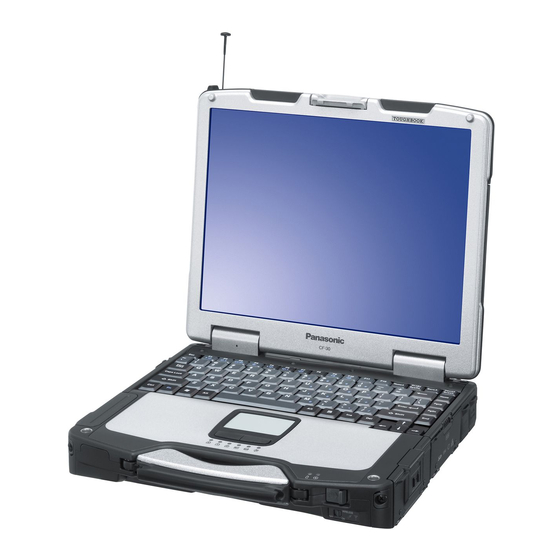
Page 8: Names And Functions Of Parts
2. Names and Functions of Parts A: Bluetooth Antenna <Only for model with Bluetooth> Reference Manual “Bluetooth” B: ExpressCard Slot Reference Manual “PC Card / ExpressCard” C: PC Card Slot Reference Manual “PC Card / ExpressCard” D: Multimedia Pocket Reference Manual “Multimedia Pocket” E: Battery Pack F: Wireless LAN Antenna <Only for model with wireless LAN>... - Page 9 Right side Rear side A: Hard Disk Drive Reference Manual “Hard Disk Drive” B: SD Memory Card Slot Reference Manual “SD Memory Card” C: SD Memory Card Indicator (Blinking: During access) Reference Manual “SD Memory Card” D: IEEE 1394 Interface Connector Reference Manual “IEEE 1394 Devices”...
-
Page 10: Block Diagram
3 Block Diagram 1Gbytes/sec... -
Page 11: Diagnosis Procedure
4 Diagnosis Procedure 4.1. Basic Procedures... -
Page 12: Troubleshooting
4.2. Troubleshooting Flow Chart... -
Page 13: Power-On Self Test (Boot Check)
5 Power-On Self Test (Boot Check) -
Page 14: List Of Error Codes
6 List of Error Codes <Only when the port replicator is connected> nnnn nnnn nnnn nnnn nnnn nnnn... - Page 15 device device device device nnnn nnnn nnnn nnnn...
-
Page 16: Self Diagnosis Test
7 Self Diagnosis Test As for the self-diagnosis test(PC-Diagnostic utility) to use this model, a standard test and the enhancing test by the module of the main body building in are possible. ●Notes To skip BIOS password Use <Ctrl>+<F10> key to skip BIOS password or authentication of fingerprint. This key is only for entering DIAG mode. - Page 17 2. Operation of PC-Diagnostic Utility -Only the device which can be inspected on the entire screen is displayed. -The item does not appear when the device of wireless LAN etc. is not physically connected. -The movement of the item must use an arrow key or a flat pad. -As for the device under the diagnosis, blue and yellow are alternately displayed at the left of the icon.
- Page 18 2-1. Selection of tested device -To test only a specific device, "Test" and "Do not test" of each device can be selected. -The device which can select the enhancing test changes in order of "The standard is tested" and "Do not test"...
- Page 19 3. Test Item and Division of trouble Enhan- Test item Stanard cing CPU is shifted to protected mode, and "Violation of the paging", "Operation of CPU / the violation of a privileged instruction", SYSTEM and DMA, INT, TIMER, and the RTC operation are confirmed.
-
Page 21: Wiring Connection Diagram
Wiring Connection Diagram PORT PORT CN100 CN102 CN101 USB PCB CN103 PORT DC-IN LAN PORT MP PCB CN400 CN402 CN401 COMBO CN28 DRIVE IEEE1394 INTERFACE CONNECTOR PW LED CN301 CN300 MAIN CARD BATTERY EXTERNAL EXPANSION DISPLAY PORT CN705 CN703 CN701 CN700 I/O PCB INVERTER PCB... -
Page 22: Disassembly Instructions
7 Disassembly/Reassembly Note: Power off the computer. Do not shut down to the Suspend or hibernation mode. Do not add peripherals while the computer is in the Suspend or hibernation mode; abnormal operation may result. 7.1. Disassembly Instructions 7.1.1. Preparation Before disassembling, be sure to make the following prepara- tions. -
Page 23: Removing The Hdd
7.1.3. Removing the HDD <K1-17> <K1-17> HDD FPC SATA Guard Sheet Heater Ins Sheet HDD Damper Ass'y Heater 1. Remove the Screw. <K1-16> 2. Remove the 4 Screws. <K1-17> And remove the SATA Guard. 3. Release the 2 Tabs, and remove the HDD U Case Ass'y and the HDD L Case Ass'y. - Page 24 7.1.5. Removing the KB Cable Cover and LCD Cable Cover <N29> <N29> <N29> <N29> <N29> to Connector to Connector (CN13) (CN14) Keyboard 1. Remove the 3 Screws <N29>. 2. Remove the LCD Cable Cover. 3. Remove the LCD Cable Plate. 4. Remove the 7 Screws <N29>. 5.
- Page 25 7.1.7. Removing the DIMM Cover and Bot- tom Cover <N1> <N1> <N1> <N1> DIMM Cover <N1> <N6> <N6> DIMM Stopper Base DIMM Heat Plate DIMM Memory Card <N17> <N8> <N8> <N17> <N8> <N6> <N6> <N8> <N6> <N6> <N6> Bottom Cover 1. Remove the 5 Screws. <N1> 2. Remove the DIMM Cover. 3.
-
Page 26: Removing The Main Pcb
7.1.9. Removing the FPC HDD BAT to Connector (CN8) to Connector (CN7) <N16> FPC HDD BAT <N29> <N29> to Connector (CN800) <N29> <N29> Tape HDD Cable Cover Pad Protect Sheet Connector (CN8) Connector (CN7) Pad PCB 1. Remove the 4 Screws. <N29> 2. Remove the HDD Cable Cover. 3. Remove the Antenna Cable Sheet. 4. - Page 27 <N18> <N16> <N16> to Connector(CN700) <N16> to Connector(CN701) <N16> <N16> Connector(CN700) Connector (CN31) Pet Tape 4. Remove the 6 Screws. <N16> 5. Remove the Screw. <N18> 6. Disconnect the 2 Cables from the 2 Connectors. (CN700,CN701) 7. Remove the Pet Tape and disconnect the Cable from the Connector.
- Page 28 7.1.12. Removing the SD PCB, Express Card and PCMCIA Card <N22> <N22> <N22> <N22> <N22> <N22> <N22> PCMCIA Card 1. Remove the 2 Screws. <N6> 2. Remove the SD PCB. 3. Remove the 4 Screws. <N22> 4. Remove the Express Card. 5.
- Page 29 7.1.14. Removing the Palm Top Cover Sheet, Palm Top Cover, Touch Pad Adhe- sion Seat, Touch Pad, Touch Pad SW Knob, LED PCB and SW LED PCB Palm Top Cover Sheet <N29> <N29> <N29> <N29> Palm Top Cover Touch Pad Adhesion Seat Touch Pad PW LED LED PCB Touch Pad SW Knob Touch Pad SW Knob In Hole 1 Hole 2 1.
-
Page 30: Removing The Display Unit
7.1.16. Removing the Display Unit <N9> <N9> <N10> 1. Remove the 2 Screws <N10> and the 4 Screws <N9>. 2. Remove the Display Unit. Screws <N9>: DRYN4+J10FKL Screws <N10>: DXSB4+15FNLB 7.1.17. Removing the LCD Rear Cabinet, Display Unit left LCD Cover Side Cover <N7> <N7>... - Page 31 7.1.18. Removing the Inverter PCB, TS PCB and LCD Unit LCD Drop Holder Connector (CN201) TS PCB Inverter PCB <N6> LCD Unit LCD Front Cabinet 1. Remove the 2 Screws. <N6> 2. Disconnect the 3 Cables from the 3 Connectors. 3. Remove the Inverter. 4. Disconnect the 2 Cables from the 2 Connectors. (CN200,CN201) 5.
-
Page 32: Reassembly Instructions
7.2. Reassembly Instructions 7.2.1. Attention when CF-30 series is repaired • Please execute writing BIOS ID when you exchange the Main Board. • Parts (Sheet and rubber) etc. related various the Conductive Cloth and Heat Spreader cannot be recycled. Use new parts. 7.2.2. - Page 33 ■ Arranging the Antenna L and R Cables Insert the cable between the pins. REAR CABLE SHEET L Put it along the inside of boss on X part Do not pinch the cable out of the cabinet Coming off the tape is arrowed Tighten the screw Safety Working S1:Insulation S2:Pinching Cables S3:Sharp Edge CAUTION S4:Part No. Check S5:Others Insert the cable between the pins. LCD REAR ASS'Y REAR CABLE SHEET R Do not pinch the cable out of the cabinet Attach it fitting to the corner Cable color: black Match it to the protrusion side and attach it betweenthe bosses. Place the anntena sub Place the anntena main 7-12 Cable color: gray REAR SCREW SHEET Match it to the concave side and attach it between the bosses. TAPE Do not pinch the cable out of the cabinet Tighten the screw...
- Page 34 7.2.3. Setting the Inverter PCB, TS PCB and LCD Unit 1. Set the LCD Unit to the LCD Front Cabinet in order. 2. Attach the 2 drop holders. 3. Connect the Cable to the Connector. (CN200,CN201) 4. Connect the 3 Cables to the 3 Connectors. 5.
- Page 35 ■ Preparation of Inverter * Notes: 1. Apply the load when attaching the parts. 20N to 30N (2 to 3Kgf)/cm2 2. When handling Inverter-PCB, do not bend or add impact. Check the Part No. N0GF1J000009(without T.S.) N0GF1J000009 N0GF2J000002 Check the Part No. HBL-0361 Inverter is set, attach...
- Page 36 7.2.4. Setting the LCD Rear Cabinet, Hinge L and R 1. Fix the Hinge L and R using the 2 Screws. <K9-1-4> 2. Set the LCD Latch. 3. Fix the LCD Rear Cabinet using the 4 Screws. <N7> No1 to 4.
- Page 37 7.2.5. Setting the Display Unit 1. Fix the Display Unit using the 4 Screws. <N9> No1 to No4 2. Fix the Display Unit using the 2 Screws. <N10> No1, No2 Note: Tighten the Screws in the numbered order (No1 to No2). Tighten the Screws in the numbered order (No1 to No4).
- Page 38 7.2.7. Setting the Palm Top Cover Sheet, Palm Top Cover, Touch Pad Adhesion Seat, Touch Pad SW Knob, LED PCB And SW LED PCB 1. Set the SW LED PCB. 2. Attach the Power LED Packing Sheet to the LED Spacer Sheet.
- Page 39 ■ Assembly of Power SW * Notes: 1. Apply the load when attaching the parts. 20N to 30N (2 to 3Kgf)/cm2 Tighten of Screw FPC Power SW is set Power SW LED Panel is set Attach the Battery Cushion Battery Pack Insertion Slot 12 2 25 2 Attach the Battery Slide Sheet (on Battery Cushion) Avoid air leaking into it. Avoid coming off 4 corners. Fit to the line. 10 1 Attach the DC Gasket Ensure the upper and lower Flex holes match. S1:Insulation S2:Pinching Cables S3:Sharp Edge CAUTION S4:Part No. Check S5:Others 7-18 Connection Direction Bottom Cable Power Connection CAB Wall Connection Direction Safety Working Attach the TP FPC Tape Match the Cabinet slit and the tape slit. Do not run the Cabinet edge out of the tape slit.
- Page 40 ■ Assembly of Palm Top Cover Using the pressure jig, Ensure the loads are applied equally. Make sure the adhesive materials are attached closely on the whole side. Process the speaker lead wire not to put inside when applying the load. Avoid running over the protrusion attached Insert FPC into the hole to the protrusion side of the upper Cabinet. of upper cabinet. Attach the Pad Attach the TP Bottom Tape Do not come over the Pad edge. Put to the arrow direction and attach it. Protrusion FFC 6LED is set 1. Apply the load when attaching the parts. 20N to 30N (2 to 3Kgf)/cm2 Ensure that the PAD and the button neck are attached with adhesive firmly. Touch Pad SW Knob Touch Pad SW Knob In is set Rubber is set Attach the PWB 6LED Put to the left and set. Insert FFC into the hole LEDX6 Spacer Notes: of upper cabinet. Sheet is set After attaching, trace around TP, ...
- Page 41 7.2.8. Setting the I/O PCB 1. Open the Connector Cover and Lid Cover. 2. Fix the I/O PCB using the 3 Screws. <N15> No1 to No3 3. Fix the I/O PCB using the 4 Screws. <N14> No1 to No4 4. Fix the I/O PCB using the 2 Screws. <N30> No1, No2 I/O PCB Connector (CN701)
- Page 42 7.2.10. Setting the Main PCB 1. Fix the Main PCB using the 8 Screws <N6> and Screw. <N11> No1 to No8. 2. Set the Modem Cable. 3. Connect the Cable to the Connector (J2) and fix the MDC. 4. Attach the Tape. 5.
- Page 43 24. Fix the Screw. <N7> 25. Attach the TOP Screws. <N7> Note: Tighten the Screws in the numbered order (No1 to No8). Tighten the Screws in the numbered order (No1 to No6). Screws <N6>: DRQT26+E4FKL Screws <N7>: DRSB26+10HKL Screws <N11>: DFHE5025XA Screws <N16>: DRQT26+E5FKL Screws <N17>: DRQT26+E6FKL Screws <N18>: DRSB26+8FKL...
- Page 44 ■ Assembly of LAN, Modem and MDC Pass the Cable to the back from the hole of the A side. LAN Cable is installed. Modem Cable is installed. ■ Assembly of Main PCB * Notes: 1. Apply the load when attaching the parts. 20N to 30N (2 to 3Kgf)/cm2 Insert the connector wrapped with the sheet into the connector on the board. Cable SATA Signal Insertion Safety Working 1 2 Sheet wrap * Notes: 1. Apply the load when attaching the parts. 20N to 30N (2 to 3Kgf)/cm2 Tighten of Screw Modem LAN Case Tighten of is installed. Screw 5 1 15 1 Attach space Attach the DMD Cable Sheet Tighten of Tighten of (Remove 2 places) Screw ...
- Page 45 7.2.11. Setting the PAD PCB 1. Fix the PAD PCB using the 2 Screws. <N29> 2. Attach the TP PCB Screw Sheet. 3. Connect the Cable to the Connector. (CN802) 4. Connect the Cable to the Connector (CN801) and attach the Tape.
- Page 46 7.2.12. Setting the FPC HDD BAT 1. Fix the FPC HDD BAT using the Screw. <N16> 2. Connect the 2 Cables to the 2 Connectors. (CN7,CN8) 3. Connect the Cable to the Connector. (CN800) 4. Attach the PAD Protect Sheet. 5.
- Page 47 1. Set HDD Guide and fix with Screw. 2. Fix with Screw. 3. Apply tetra coating to each connector pin. Direction B View Tighten of Screw Direction A View Do not Fold. (R1 4) Battery HDD Connector Angle is set HDD Guide is set Direction C View 7-26 FPC HDD Battery is set This Connector does not need tetra coating. Tighten of Tighten of Screw Screw ...
- Page 48 The terminal of the antenna cable must not come in contact with this terminal. (Put it on the metal fittings side. ) Figure seen from direction of arrow of A Valley Fold (Dotted Line) 7.2.13. Setting the USB PCB and Antenna PCB 1. Open the Connector Cover. 2. Fix the Antenna PCB using the 2 Screws. <N3> 3. Connect the 2 white Cables. 4. Fix the USB PCB using the Screws. <N6> 5.
- Page 49 ■ Assembly of USB PCB * Notes: 1. Apply the load when attaching the parts. 20N to 30N (2 to 3Kgf)/cm2 Order of fixing Screw Screw W-LAN Cable Connection EXT Antenna PCB is set Connect the coaxial cable from LCD. Tighten of Screw Tighten of Screw S1:Insulation S2:Pinching Cables S3:Sharp Edge CAUTION S4:Part No. Check S5:Others PCB USB Sub is set Tighten of Screw Safety Working Attach the Tape Set on the top. Process the cable from LCD. * Notes: 1. Apply the load when attaching the parts. 20N to 30N (2 to 3Kgf)/cm2 7-28 Safety Working Attach the Antenna Cable Sheet Fit to the groove. Difference : 1 or less Antenna Cable Plate is set Tighten of Screw Along the groove Pull W-LAN Cable out to the surface from the hole. Match to the board edge. ...
- Page 50 7.2.14. Setting the DIMM Cover and Bottom Cover 1. Set the Bottom Cover. 2. Fix the Bottom Cover using the 6 Screws. <N8> No1 to No6 3. Fix the Bottom Cover using the 11 Screws. <N6> No1 to No11 4. Fix the Bottom Cover using the 2 Screws. <N17> No1, No2 5.
- Page 51 ■ Preparation of DIMM Cover Attach the DIMM Cover Cushion Attach the DIMM Cover Spacer 0 0.5mm * Notes: 1. Apply the load when attaching the attaching parts. 20N to 30N (2 to 3Kgf)/cm2 LCD Cable Cover is set 1.5 2.5mm Attach the CD Edge Sheet Attach the LCD Cable Cover Cushion * Notes: 1. Apply the load when attaching the parts. 20N to 30N (2 to 3Kgf)/cm2 DIMM Cover is set 0 0.5mm 0 0.5mm 0 0.5mm S1:Insulation S2:Pinching Cables S3:Sharp Edge CAUTION S4:Part No. Check S5:Others Keyboard Cable Cover is installed 4 6mm Safety Working Attach the Keyboard Cable Cover Cushion 7-30 Safety Working Attach the CD Edge Sheet 0 1mm 4 6mm...
- Page 52 7.2.15. Setting the GPS PCB and Bluetooth PCB 1. Fix the GPS BT Angle and GPS PCB using the 2 Screws. <N11> 2. Connect the Cable to the Connector on GPS PCB. 3. Fix the GPS Ass’y using the 4 Screws. <N12> 4.
- Page 53 7.2.16. Setting the KB Cable Cover, Keyboard and LCD Cable Cover 1. Set the Keyboard onto the Computer. 2. Connect the 2 Cables to the 2 Cables. (CN13,CN14) 3. Fix the KB Cable Cover using the 7 Screws. <N29> No1 to 4.
-
Page 54: Setting The Hdd
7.2.17. Setting the KB Cover, Hinge Cover L, Hinge Cover R and Keyboard 1. Insert the front hooks of the Keyboard to the Top Cabinet in order, and set the Keyboard. 2. Fix the Hinge Cover L and R using the 3 Screws <N6> No1 to No3 3. - Page 55 ■ Preparation oh HDD ASSY Fit to the corner. HDD INS SHEET Safety Working PET TAPE HEATER FIXED TAPE * Notes: 1. Apply the load when attaching the parts. 20N to 30N (2 to 3Kgf)/cm2 HDD TAPE S Turn it to the board side (back side). 1. Do not gouge when inserting and removing the socket. 2. Do not drop HDD or add any impacts on it. 3. Insert CN into the end firmly. 4. Apply the load when attaching the parts. 20N to 30N (2 to 3Kgf)/cm2 Attach it pushing the shaded HEATER part not to push the fuse. Center 7-34 S1:Insulation S2:Pinching Cables S3:Sharp Edge CAUTION S4:Part No. Check S5:Others Valley Fold Mountain Fold Do not bend the bending part of Heater Connect the Connector Insert the HDD FPC Ass'y...
- Page 56 Do not place the damper over the plate of FPC. HDD Damper Ass'y Make sure the product with black sheet on the yellow sponge. HDD Ass'y HDD Set Insert after removing the Release Paper of the two-sided tape. * Notes: 1. Apply the load when attaching the parts. 20N to 30N (2 to 3Kgf)/cm2 HDD Thermal Plate To the level of attaching closely in this range Prepare the metal plate bend. * Notes: 1. Apply the load when attaching the parts. 20N to 30N (2 to 3Kgf)/cm2 Fold the FPC from the board edge. Remove the Release Paper on the back, close and attach it. Attach it to HDD closely not to loosen. When attaching HDD Cushion (Yellow) and HDD Cushion (Black), set the bending part of the metal plate up. 1 3 Do not bend it at a sharp angle to put natural R. Longer Direction Attach the HDD Cushion (Yelllow) Attach the HDD Cushion (Yelllow) Attach the HDD Cushion (Black) Sheet 7-35 Do not place the damper over the plate of heater. Push and bend 1 3 HDD Cushion (Black) Metal Plate Attach the HDD Thermal Plate...
- Page 57 * Notes: 1. Apply the load when attaching the parts. 20N to 30N (2 to 3Kgf)/cm2 HDD Thermal Plate To the level of attaching closely in this range When attaching HDD Cushion Plate and HDD Cushion (Black), set the bending part of the metal plate up. Do not bend it at a sharp angle to put natural R. Longer Direction Attach the HDD Cushion (Yellow) Attach the HDD Cushion (Black) Attach the HDD thermal Plate *Ensure the direction is right. (lateral) 7-36 1 3 1 3 HDD Cushion (Black) Metal Plate Attach the HDD Cushion (Yellow) Put the edge on the same line. Difference: 1...
- Page 58 * Notes: 1. Apply the load when attaching the parts. 20N to 30N (2 to 3Kgf)/cm2 Paste the cushion with pressing in the direction of arrow. B-B SEC Right and left position: Match to the center Top and bottom position: Match the edge of the base material transparent sheet to the bottom side (20) HDD Side Damper is installed HDD Side Damper 0 0.5 (Entire Circumference) A-A SEC HDD Bottom Case Ass'y 7-37 Make the black damper get int both sides of the green dampe Lower Case...
- Page 59 HDD Ass'y insertion * Notes: 1. Apply the load when attaching the parts. 20N to 30N (2 to 3Kgf)/cm2 Tighten of Screw Tighten of Tighten of Screw Screw Tighten of Screw Confirm that the CN board moves up/down and right/left after assembling. SATA Guard is installed Insert to make the Cushion on the HDD inside of the Cushion on the lower case. Avoid getting HDD under the side damper when inserting HDD Order of fixing Screw Screw 7-38 Set the CN side first, and then set the TAB side pushing to the A direction. SATA Guide Set Screw Screw Tighten of Screw ...
- Page 60 7.2.19. Setting the Battery Pack and HDD Pack 1. Set the HDD Pack. 2. Set the Battery Pack. Battery Cover Battery Pack 7-39 HDD Cover HDD Pack...
-
Page 61: Exploded View
(2.0 _ 0.2 kgf.cm) E1001 K2-48 K2-42 K2-49 K2-46 K2-45 K1201 K1122 K1-17 K1214 K1-9 K1202 K1210 N29 N29 K1-17 K1-1 K1-20 K1-4 K1-19 K1-8 K1-11 K1-18 K1-14 K1-4 K1-15 K1-13 K1-3 K1-16 K1-4 K1-19 K1-5 K1-5 K1-20 K1-6 K1-4 K1-6 K1-2 CF-30FTSAZAM... - Page 62 K2-23 K2-47 K2-4-2 K2-4-4 K2-13 K2-14 K163 K102 K103 K2-15 K2-36 K105 K2-43 K106 K113 K2-31 K2-42 K2-2-7 K2-2 K2-2-6 K2-2-2 K2-7 K2-2-5 K2-2-1 K2-2-4 K2-7-1 K2-7-2 K2-7-3 K2-9 K2-7-1 K2-39 CF-30FTSAZAM K2-10-8 K2-39 K2-4 K2-4-3 K2-4-1 K114 K121 K2-7-4...
- Page 63 K2-28 K148 K149 K118 K153 K1214 K1203 K1214 K143 K110 K161 K124 K132 K117 K1123 K1208 K1206 K123 K1208 K144 K1207 K1214 K1205 K137 K1209 K139 K153 K140 K131 K142 K1212 K148 K148 K135 K145 K141 K149 K1155 K1204 CF-30FTSAZAM...
- Page 64 K118 K2-33 K3-8 K2-32 K3-3 K2-39 K2-39 K2-34 K1213 K3-8 K3-8 K3-3 K3-8 K3-4 K3-2 K3-7 K3-9 K3-6 K3-5 K3-4 K3-1 Screw tightening torque 0.45 _ 0.05 N.m (4.5 _ 0.5 kgf.cm) 0.8 _ 0.1N.m (8.0 _ 1.0 kgf.cm) 0.3 _ 0.05 N.m (3.0 _ 0.5 kgf.cm) 0.19 _ 0.05 N.m (2.0 _ 0.5 kgf.cm) CF-30FTSAZAM...
- Page 65 K9-2 K9-1-3 K10-2 K9-1-2 K9-1-4 K9-1-3 K9-2-1-1 K9-2-2 K10-1 K9-4 K9-3 K9-1-3 K9-1-1 K9-1-3 K9-2-3 Screw tightening torque 0.19 _ 0.02 N.m (2.0 _ 0.2 kgf.cm) K9-1 0.45 _ 0.50 N.m (4.5 _ 0.5 kgf.cm) 0.441 _ 0.049 N.m (4.5 _ 0.5 kgf.cm) K9-1-4 1.47 _ 0.20 N.m (15 _ 2.0 kgf.cm) 1.30 _ 0.17N.m (13.0 _ 2.0 kgf.cm) CF-30FTSAZAM K1151...
- Page 66 E35-2 E35-5 E35-10 E35-8 E35-3 E35-4 E35-4 E35-3 E35-1 K1214 K1214 E35-6 K1214 K1214 E35-7 E35-10 E35-9 Screw tightening torque 0.19 _ 0.02 N.m (2.0 _ 0.2 kgf.cm) 0.45 _ 0.05 N.m (4.5 _ 0.5 kgf.cm) 0.216 _ 0.0196 N.m (2.2 _ 0.2 kgf.cm) 0.314 _ 0.0196 N.m (3.2 _ 0.2 kgf.cm) 0.49 _ 0.05 N.m (5.0 _ 0.5 kgf.cm) CF-30FTSAZAM...
- Page 67 K1031 K13-1 K13-2 K1032 Screw tightening torque 0.19 _ 0.02 N.m (2.0 _ 0.2 kgf.cm) 0.45 _ 0.05 N.m (4.5 _ 0.5 kgf.cm) 0.216 _ 0.0196 N.m (2.2 _ 0.2 kgf.cm) 0.314 _ 0.0196 N.m (3.2 _ 0.2 kgf.cm) 1.47 _ 0.20 N.m (15 _ 2.0 kgf.cm) 0.49 _ 0.05 N.m (5.0 _ 0.5 kgf.cm) CF-30FTSAZAM...
-
Page 68: Replacement Parts List
Replacement Parts List Note : Important Safety Notice Components identified by When replacing any of these components, use only manufacturer's specified parts. CF-30FTSAZAM REF. NO and AREA Main Block Unit DL3UP1336BAA DL3UP1354CAA DL3UP1630AAA DFWP0150ZA DL3UP1543AAA DL3UP1580AAA DL3U11540BAA DL3U21540BAA DL3U31540BAA DL3U41540BAA DL3U61540BAA... - Page 69 Accessories S NCR-B/901A S CF-AA1653ASA DFHR6207ZA DFHS9017ZA DFME0148YA S DFQW5098ZA S K2CG3DR00003 DFJS954ZA DFHR6339ZA-0 DFHR6340ZA-0 S DFKE0911ZC-0 DFQM8357MA Packing Material DFPH0064ZA DFPP0143ZA DFPE0852ZA DFPN0845ZA DFPK1202WA Mechanical Parts DFWV99A0125 K1-1 DL3UP1557AAA K1-2 DFMD8041YA K1-3 DFMD8042YA K1-4 DFHG1750YB K1-5 DFHG1933ZA K1-6 DFHG1934ZA K1-8 DFHP7101ZA K1-9...
- Page 70 K2-4-3 DFUQ0113ZA K2-5-4 DRHM0110ZAT K2-5 S DFKE8187YA-0 K2-5-1 DFBD0193ZA-0 K2-5-2 S DFKE0869YA-0 K2-5-3 DFUQ0116ZA K2-5-4 DRHM0110ZAT K2-6 S DFKE8188ZA-0 K2-6-1 DFBH3051ZA K2-6-2 DFGE0139ZA-0 K2-6-3 DFHR3E55ZA K2-6-4 S DFKE0860ZA-0 K2-6-5 DRQT26+D3KLT K2-7 S DFKE8189YA-0 K2-7-1 DFBH3051ZA K2-7-2 DFGE0140YA-0 K2-7-3 S DFKE0866ZA-0 K2-7-4 DRQT26+D3KLT K2-8...
- Page 71 K2-20 DFHG1931ZA K2-21 DFHG1973ZAT K2-22 DFHM0419YA K2-23 DFHR3D56ZA-0 K2-24 DFHR3E66ZA K2-25 DFHR6291YB-0 K2-26 S DFKE0851ZB-0 K2-27 S DFKE0852ZB-0 K2-28 S DFKE0856ZB-0 K2-29 S DFKE0876ZB K2-30 S DFKM0516WA-0 K2-31 DFMD2170ZA K2-32 DFMD2172ZA K2-33 DFMY0414ZA K2-34 DFMY5037ZA K2-36 DFUQ0102ZA K2-37 DFWP0145YA K2-38 DRHM0118ZAT K2-39 DRQT26+D3KLT...
- Page 72 DFWV80C0513 K13-1 S DFKM8184ZA-0 K13-1-1 S DFKM0517ZA-0 K13-2 DFGB0131YA-0 DFHG1886ZA DFHG1887ZA DFHG1888ZA DFHG1890ZA DFHR3E98ZA DFHR3E99ZA DFHR3G26ZA DFHR3G27ZA DFHR6270YA DFHR6296ZA S DFKE0857ZA-0 S DFKE0858YC-0 S DFKE0859ZB-0 S DFKE0873ZB-0 S DFKE0874ZB-0 DFMD2177ZA DFMX0634ZA DFMX0999ZA DFMY0438ZA DFHR3E83YA DFMD7B13ZA DFMX1260YA DFGX0457ZB-0 DFGX0458ZB-0 DFGX0459ZB-0 DFGX0460ZB-0 DFHG1881ZA DFHG1884ZA DFHG1942ZA...
- Page 73 DFHR3619ZA DFHR3636ZA DFHR3643ZA DFHR3E67ZA DFHR3E93VA DFHR3F46ZA DFHR3F49ZA DFHR3F87YA K100 DFHR3G02ZA K101 DFHR3G03ZA K102 DFHR3G04ZA K103 DFHR3G05ZA K104 DFHR3G09ZA K105 DFHR3G10ZA K106 DFHR3G25ZA K107 DFHR3G32ZA K108 DFHR3G41ZA K109 DFHR6355ZA K110 DFHR6246ZA K111 DFHR6247ZB K112 DFHR6253YA-0 K113 DFHR6254YA-0 K114 DFHR6255YA-0 K116 DFHR6259YC-0 K117 DFHR6295ZA K118...
- Page 74 K1201 DFHR3K09ZA K1202 DFHR3H39YA K1203 D4CZY103A003 K1204 DFHE0915ZA K1205 DFHG830ZA K1206 DFHR3F89ZA K1207 DFHR3K18ZA K1208 DFMY0486ZA K1209 DFMY0487ZA K1210 DFHE1106ZA K1211 DFHR6354ZA-0 K1212 DFHG2077ZA K1213 DFQT0055YA K1214 DFMX0383TA DRHM0002ZA DRHM5054XA DRQT2+G6FKL DRQT26+E4FKL DRSB26+10HKL DRSB3+8FKL DRYN4+J10FKL DXSB4+15FNMB DFHE5025XA DXQT2+F3FNL DRSB4+10FKL DFHE5058ZB DRHM5104ZA DRQT26+E5FKL DRQT26+E6FKL...
- Page 75 Replacement Parts List Note: Important Safety Notice Components identified by When replacing any of these components use only manufacturer's specified parts. CF-30FTSAZAM REF. NO and AREA MAIN PCB C 1, 2, 3, 5, 6, 7, 10, 11, 12, 14, 15, 16, 18, 19,...
- Page 76 C 55, 72, 91, 152, 153, F1G1E103A062 154, 155, 200, 201, 202, 203, 211, 215, 229, 280, 299, 309, 313, 340, 397, 399, 400, 405, 406, 412, 422, 423, 435, 443, 468, 519, 525, 557, 569, 574, 575, 579 C 59, 60, 103, 105, 110, F1G0J224A001 113, 119, 120, 375, 383, C 63, 65, 73, 77, 80, 81,...
- Page 77 C 491, 562, 621 F1G1H470A542 C 492, 629 F1G1H151A495 C 494, 624 F1H1H1830001 C 495, 631 F1G1H561A496 C 501, 570, 623 F1G1H331A496 C 508, 509, 510, 526, 571, F1L1E106A017 596, 606, 614, 615 C 512, 513, 514, 612 EEFSX0D471XE C 515, 552 EEFCD0D151ER C 517, 546, 558, 616 F1H1C224A074...
- Page 78 D 33, 34, 35, 36, 37, 38, MAZ80620ML 62, 63 D 39, 55 MA3S132E0L D 40 B2ABAM000002 D 42 MA2S111-TX D 43, 45, 50, 57, 64 B0JDBE000002 D 44 B0JDRE000007 D 51 MAZ81200ML D 52 MAZ81800ML D 54 B0KB00000044 F 1, 4, 7 S K5H502Z00003 F 2, 5, 6, 8, 12 S K5H202Z00005...
- Page 79 IC 79, 80, 88 C0JBAZ002836 IC 81 C0DBGYY00423 IC 83, 84 C0JBAZ002837 IC 85 C0JBAC000367 IC 89 C0DBZYY00017 IC 92 C1CB00002497 IC 94, 95 C0JBAZ002372 IC 99 AN12945A-VB IC 100 C0JBAC000363 IC 102 C0CBCAC00161 IC 106 C0JBAZ002387 IC 126 C0DBAYY00282 IC 127 C0JBAR000515 IC 128...
- Page 80 Q 79, 105, 106, 113, 114, B1CHRD000001 122, 124, 136 Q 92, 97 B1DHDD000031 Q 116 XP0421400L Q 125 B1MBEDA00008 R 1, 2, 27, 39, 41, 43, 118, ERJ2GEJ102X 190, 191, 262, 263, 378, D1H85104A024 R 7, 31, 66, 68, 70, 480, ERJ2RKF1001X 481, 518, 650, 657, 673 R 8, 32...
- Page 81 R 85, 88, 245, 491, 492, ERJ3GEY0R00V 624, 632, 634 R 93, 94, 96, 98, 99, 101 D1HY5608A007 R 95, 100, 248 D1H85604A024 R 105, 106, 188, 189 D1H83304A024 R 111, 253, 334, 498, 499, ERJ2GEJ100X 515, 516, 527, 528, 540, 541, 553, 554, 674, 675 R 126, 148 D1H84724A024...
- Page 82 R 336, 337 ERJ2GEJ333X R 340, 341, 367, 371, 472, ERJ2RHD104X 545, 582, 583 R 348 ERJ2RKF1602X R 349 ERJ2RKF9091X R 365 ERJ2RKD684X R 368, 370, 655 ERJ2RKD154X R 372 D1ZZ00000046 R 386, 450, 538, 588, 592, ERJ2GEJ473X 593, 598, 599 R 388 D1H81014A024 R 394, 398, 438...
- Page 83 R 651, 656 ERJ2RKF6981X R 658 ERJ2RKF1691X R 659 ERJ2RKF1433X R 661, 662 ERJ2GEJ392X R 663, 664 ERJ2GEJ4R7X T 1, 2 G5BYC0000015 H0J143500058 H0J327200115 H0J250500076 H2D800400015 H0J245500083 H0J240500033 ZA 1, 2, 7 K1YGZZ000060 ZA 3, 4 K1YGZZ000065 IO PCB C 700, 702, 718, 738, F1G1C104A042 739, 747 C 701...
- Page 84 D 800 DED1SS355T17 IC 800 C1DB00001417 Q 800, 801 B1GKCFJN0004 R 800 ERJ2GEJ224X R 801, 803 ERJ2GEJ822X R 802 ERJ2GEJ273X R 804 ERJ2GEJ105X R 805, 806 ERJ2GEJ222X R 808 D1H81034A024 SW 800, 801 EVQPLDA15 X 800 H2D400400012 SD PCB C 300 F1G1A104A014 CN 300 K1MN12BA0134...
- Page 85 R 200, 206 ERJ2GEJ473X R 203, 205, 207, 209, 210, ERJ2GEJ102X 211, 212, 217, 220, 221, 222, 223 R 208 ERJ2GEJ273X R 213, 214, 215, 216 ERJ2GEJ822X R 218 ERJ2GEJ512X R 226 DEARA8AJ473M R 227, 228 ERJ2GEJ270X R 229 ERJ2GEJ152X X 200 H2D600400005 BT PCB...
Need help?
Do you have a question about the CF-30FTSAZAM and is the answer not in the manual?
Questions and answers