Table of Contents
Advertisement
Quick Links
Advertisement
Table of Contents

Related Manuals for Invacare LiNX DLX-ACU200


Summary of Contents for Invacare LiNX DLX-ACU200
- Page 1 Invacare® LiNX DLX-ACU200, DLX-CR400, DLX-CR400LF, Supplement to power wheelchair user manual en Remote User Manual This manual MUST be given to the user of the product. BEFORE using this product, this manual MUST be read and saved for future reference.
- Page 2 All rights reserved. Republication, duplication or modification in whole or in part is prohibited without prior written permission from Invacare. Trademarks are identified by ™and ®. All trademarks are owned by or licensed to Invacare Corporation or its subsidiaries unless otherwise noted.
-
Page 3: Table Of Contents
4.7 Connecting the remote ......22 Contents 5 Maintenance ........23 5.1 Maintenance . -
Page 4: General
We provide a manufacturer’s warranty for the product product safety notices and product recalls, contact your in accordance with our General Terms and Conditions of Invacare representative. See addresses at the end of this Business in the respective countries. document. -
Page 5: Limitation Of Liability
LiNX DLX-ACU200 also be considerably reduced by extreme or incorrect usage. The LiNX DLX-ACU200 is a secondary remote module of the The fact that we estimate a service life for this product does LiNX family, intended to allow an attendant of a powered not constitute an additional warranty. -
Page 6: Safety
Invacare® LiNX 2 Safety WARNING! Risk of injury or damage due to electrical shorts Connector pins on cables connected to the power 2.1 General safety notes module can still be live even when the system is off. WARNING! – Cables with live pins should be connected,... - Page 7 Safety Risk of damage to the mobility device There are no user-serviceable parts inside any case. – Do not open or disassemble any case. 1608055-C...
-
Page 8: Components
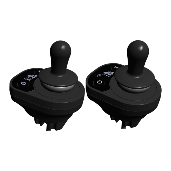
Invacare® LiNX 3 Components • power up or A Power button (with status power down the LED), EMERGENCY STOP system, if remote is 3.1 Attendant control unit remote-in-charge • view the system's The remote is the input that operates the mobility device’s status functions and defines the icon displayed. -
Page 9: Compact Remote Module
Components 3.2 Compact remote module • power up or A Power button (with status power down the LED), EMERGENCY STOP The remote is the input that operates the mobility device’s system, if remote is functions and defines the icon displayed. remote-in-charge •... -
Page 10: Drive/Seating Function Indicators
Invacare® LiNX 3.3 Drive/Seating Function Indicators can be up to four attendant drive functions, one is set as a factory default. Drive Function Indicator (CREM and CREM-LF Only) Fig. 3-3 The drive function indicator shows the selected compact Fig. 3-1 remote drive function using one or more LEDs. - Page 11 Components • Mobility device can be driven at reduced speed only. Icon Seating function See 4.6.6 Drive slow-down indication, page 20. Right Leg • Joystick is not in center position. See 4.6.5 OON Indication, page 20. • Mobility device can not be driven at all. See 4.6.8 Blocked function indication, page 21 and 4.6.7 Lock-out indication, page 20.
-
Page 12: Labels On The Product
Invacare® LiNX 3.4 Labels on the product Product label containing: • Dynamic Controls' website address • The product's bar code • The product's serial number • The product's part number • Dynamic Controls' 'dynamic' logo WEEE Conformity Recommendation to read the user manual before using the module. - Page 13 Components 1. Hardware version 2. Hardware major version 3. Hardware minor version 4. Application version 5. Application major version 6. Application minor version Serial number and date of manufacture The serial number on a Dynamic Controls product provides both the date of manufacture as well as a unique serial number for the particular module.
-
Page 14: Usage
Invacare® LiNX 4.2 Using the joystick 4 Usage CAUTION! 4.1 Requesting control of the mobility device Risk of injury The secondary remote modules may only be used The remote-in-charge is the remote that controls the with the authorized joystick knobs. -
Page 15: Power Button (With Status Led)
Usage 4.3 Power button (with status LED) Powering up and down Press the button to switch the system ON. Power button on attendant If there is no fault with the system, the status indicator Power button on compact control unit lights up green. -
Page 16: Mode Button
Invacare® LiNX mobility device the remote of the user, that wants to stop Connectivity gives access to more profiles. Connectivity can the mobility device must be remote-in-charge. If the remote be disabled. that you want to perform an emergency stop on is not remote-in-charge, you must request control/ to be in-charge of the mobility device first. - Page 17 Usage The Mode button B is on the right-hand side of the remote module and contains a status LED that lights up, flashes or pulses depending on the status of the system: Short press the button until the correct/seating function •...
-
Page 18: Lock Mode
Invacare® LiNX 4.5 Lock Mode The lock mode is not set at the factory for every system, but can be enabled by your provider. If this parameter is set ON, Press the button once to power up. you can use the lock function to restrict who can use the 2. -
Page 19: Reading The Indicators
If the primary remote has control of the system, all LEDs are green, then dims and finally switches off again. switched off on the attendant control unit. For restricting a remote, contact your Invacare 4.6.2 User-in-Charge Indication (Compact Remote Module) provider. -
Page 20: Oon Indication
Invacare® LiNX Seating OON Warning Deactivate sleep mode during transition period by moving joystick or pressing power button. For setting sleep mode, contact your Invacare provider. Fig. 4-8 4.6.5 OON Indication When the system is powering up or after a function change, no direct access switches can be active, otherwise a seating OON (“Out Of Neutral”) is a safety feature that prevents... -
Page 21: Blocked Function Indication
Usage Drive lock-out 4.6.8 Blocked function indication A blocked function indication is displayed if the user tries to change a function while operating in another function. A change of function is by default not permitted. A drive lock out is a state that prevents the mobility device The blocked function indication differs depending on what from being driven. -
Page 22: Connecting The Remote
Invacare® LiNX • the seating indicator switches off while the drive wheel indicator flashes. 4.7 Connecting the remote CAUTION! Risk of unintended stops If the plug of the remote cable is broken, the remote cable may come loose while driving. The remote could suddenly switch off when losing power. -
Page 23: Maintenance
If any component is damaged in any way, or if internal damage may have occurred (for example by being dropped), have it checked by qualified personnel before operating. Where any doubt exists, consult your nearest Invacare provider. 1608055-C... -
Page 24: Troubleshooting
24. cause the mobility device to stop, while less critical ones are indicated but allow the mobility device to Contact your Invacare provider. continue driving. Some faults automatically clear when the fault condition is removed (non-latched) while others are latched and must be cleared by turning the controller off, waiting five seconds, then turning the system on again. - Page 25 Troubleshooting The table below describes the fault indication, and a few possible actions that can be taken to rectify the problem. The actions listed are not in any particular order and are suggestions only. The intention is that one of the suggestions may help you clear the problem.
- Page 26 Invacare® LiNX Flash code Fault description Possible action Right magnetic brake fault • Check cables and connectors. • Check right magnetic brake is engaged. • Refer to the chapter “Pushing the mobility device in freewheel mode” in the user manual of your wheelchair.
-
Page 27: Technical Data
Technical Data 7 Technical Data 7.1 Technical specifications Mechanical specifications Permissible operating, storage and humidity conditions • –25° ... +50 °C Temperature range for operation according to ISO 7176–9: Recommended storage temperature: • 15 °C Temperature range for storage according to ISO 7176–9: •... - Page 28 Notes...
- Page 29 Notes...
- Page 30 Notes...
- Page 31 www.invacarelinx.com...
- Page 32 Invacare Sales Companies Australia: Canada: Ireland: New Zealand: Invacare Australia Pty. Ltd. Invacare Canada L.P. Invacare Ireland Ltd, Invacare New Zealand Ltd 1 Lenton Place, North Rocks NSW 570 Matheson Blvd East, Unit 8 Unit 5 Seatown Business Campus 4 Westfield Place, Mt Wellington 1060 2151 CDN Mississauga, On.
Need help?
Do you have a question about the LiNX DLX-ACU200 and is the answer not in the manual?
Questions and answers