Invacare Dragon Vertic User Manual
Electric wheelchair
Hide thumbs
Also See for Dragon Vertic:
- User manual (112 pages) ,
- Service manual (67 pages) ,
- User manual (72 pages)
Table of Contents
Advertisement
Quick Links
Advertisement
Table of Contents

Related Manuals for Invacare Dragon Vertic


Summary of Contents for Invacare Dragon Vertic
- Page 1 Invacare® Dragon Vertic Electric Wheelchair User Manual...
- Page 2 How can you get in touch with Invacare®? If you have any questions or need support, please contact your authorised Invacare® Dealer, who has the necessary know-how and equipment plus the special knowledge concerning your Invacare® product, and can offer you all-round satisfactory service. Should you wish to contact Invacare® directly, you can reach us in Europe at the following addresses and phone numbers.
- Page 3 +31 - (0) 318 - 69 57 57 Fax (Kundeservice): +47 - 22 57 95 01 Fax: +31 - (0) 318 - 69 57 58 Invacare® PORTUGAL Lda Invacare® AB Rua Senhora de Campanhã, 105 Fagerstagatan 9 4369-001 Porto 163 91 Spånga...
-
Page 4: Table Of Contents
Table of Contents Chapter Page Introduction Important symbols in this manual ..................10 Important symbols found on the vehicle ................11 Type classification and permissible use................13 1.3.1 Indications........................14 Safety Notes General Safety Notes ......................16 Safety Information on Electromagnetic Interference............19 Safety Information on Driving and Freewheel Mode............20 Safety information for using the wheelchair as a vehicle seat...........22 Safety information for the verticalizer...................23 Key features... - Page 5 Disengaging Motors ........................31 The Shark II Remote Assembly of the remote......................32 Battery charging display......................34 Status display ..........................35 Activate/de-activate the immobiliser ..................35 Using the remote to control the wheelchair .................36 7.5.1 How a wheelchair with "Indirect Steering" reacts to joystick movements.....37 7.5.2 Operating the electric adjustment options ..............38 Control unit for an accompanying person (option) .............39...
- Page 6 8.6.2 Setting the angle of the swing-up armrest ..............62 8.6.3 Setting the resistance of the swing-up armrest ............63 8.6.4 Adapting the remote to the length of the user’s arm ............64 8.6.5 Setting the height of the remote ...................65 8.6.6 Setting the width of the side sections ................66 Adapting the height of the chest belt ..................68 Adjusting the backrest......................70 Adjusting the headrest......................70...
- Page 7 12.2 Securing the wheelchair for transport without passengers ..........93 13 Refurbishment 14 Disposal 15 Technical Specifications 16 Inspections Performed...
-
Page 8: Introduction
The decision whether the model is suitable for the user may only be taken by medical specialists with appropriate expertise. Invacare® or their statutory representatives can accept no liability in cases in which the wheelchair has not been adapted to suit the users’ handicaps. - Page 9 This manual contains copyrighted information. This manual may not be reproduced or reprinted either partly or completely without previous written consent from Invacare® or its statutory representatives. We reserve the right to make any necessary alterations on the grounds of...
-
Page 10: Important Symbols In This Manual
Important symbols in this manual WARNING! This symbol warns you of danger! • Always follow the instructions to avoid injury to the user or damage to the product! EXPLOSION HAZARD! This symbol warns you of an explosion hazard, which can be caused by excessive tyre pressure in a pneumatic tyre! •... -
Page 11: Important Symbols Found On The Vehicle
Important symbols found on the vehicle DO NOT DRIVE OVER UNEVEN GROUND! Danger of tipping over! DO NOT LEAN OUT OF THE RAISED VERTICALIZER! Danger of tipping over! THE VERTICALIZER IS NOT DESIGNED TO TRANSPORT MORE THAN ONE SINGLE PERSON! Danger of injury! NEVER DRIVE ON ASCENDING OR DOWNWARD SLOPES WHEN THE VERTICALIZER IS RAISED! Danger of tipping over! NEVER REACH INTO THE MOVING APPARATUS OF THE RAISED VERTICALIZER! - Page 12 This product has been supplied from an environmentally aware manufacturer that complies with the Waste Electrical and Electronic Equipment (WEEE) Directive 2002/96/CE. This product may contain substances that could be harmful to the environment if disposed of in places (landfills) that are not appropriate according to legislation.
-
Page 13: Type Classification And Permissible Use
Type classification and permissible use The Dragon erect chair is a class B electric wheelchair (for use indoors and outdoors) with an ability to overcome curbstones and obstacles restricted to 40 mm. It serves the mobility of handicapped people requiring slight to medium clinical support. Driving indoors and outdoors is carried out in the seated position. -
Page 14: Indications
1.3.1 Indications Before using the Invacare® Dragon Vertic for the first time, you should consult your doctor! Before using the verticalizer on a daily basis, we recommend medical/physiotherapeutic accompaniment in order to become accustomed to the modified posture. The use of this mobility product is recommended for the following indications: Paralysis •... - Page 15 Other illnesses • Disequilibrium • Cachexia Provision of electric wheelchairs for indoors and in road traffic is advised if the use of hand- operated wheelchairs is no longer possible on account of the handicap or if greater distances have to be covered on a regular basis and the wheelchair also has to be used indoors elsewhere. The decision as to whether the model is suitable for you as user rests exclusively with the adequately skilled specialised medical staff.
-
Page 16: Safety Notes
Safety Notes • READ WELL BEFORE OPERATION! General Safety Notes Danger of injury if wheelchair is used in any other way than the purpose described in this manual! • Only ever use the wheelchair in accordance with the instructions in this User's Manual! •... - Page 17 Danger of injury if the wheelchair is switched off while driving, for example by pressing the On/Off Button or disconnecting a cable, due to it coming to an abrupt, sharp stop! • If you have to brake in an emergency, simply release the joystick which will bring you to a halt! Danger of injury when transferring wheelchair to another vehicle for transport with the occupant seated in it! •...
- Page 18 Danger of fire or breaking down due to electric devices being connected! • Do not connect any electric devices to your wheelchair that are not expressly certified by Invacare® for this purpose! Have all electrical installations done by your authorised Invacare® Dealer!
-
Page 19: Safety Information On Electromagnetic Interference
Safety Information on Electromagnetic Interference This electric vehicle was successfully tested in accordance with International standards as to its compliance with Electromagnetic Interference (EMI) Regulations. However, electromagnetic fields, such as those generated by radio and television transmitters, and cellular phones, can influence the functions of electric vehicles. -
Page 20: Safety Information On Driving And Freewheel Mode
Safety Information on Driving and Freewheel Mode Danger of injury if the wheelchair tips over! • Only ever negotiate gradients up to the maximum tilt-resistant gradient (see Technical Specifications) and only with the backrest and seat tilt (if fitted) in an upright position! •... - Page 21 Danger of breaking down in adverse weather conditions, i.e. extreme cold, in an isolated area! • If you are a user with severely limited mobility, we advise that in the case of adverse weather conditions DO NOT attempt a journey without an accompanying attendant! Danger of injury if your foot slides off the footrest and gets caught underneath the wheelchair when it is in motion! •...
-
Page 22: Safety Information For Using The Wheelchair As A Vehicle Seat
Safety information for using the wheelchair as a vehicle seat Danger of injury in the event of the wheelchair being used as a vehicle seat. • Never use the wheelchair as a vehicle seat. • Only ever transport the wheelchair without occupants. •... -
Page 23: Safety Information For The Verticalizer
Safety information for the verticalizer CAUTION: Danger of tipping! • When the verticalizer is raised drive operation only serves positioning and not normal driving. • Never drive over uneven ground, on an upward or downward slope or over obstacles when the verticalizer is raised. -
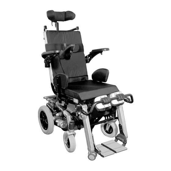
Page 24: Key Features
Key features 1) Release handle for headrest adjustment 2) Sliding handle 3) Chest belt 4) Set screw for adjusting the position of the remote 5) Side section fastening screw 6) Disengaging lever 7) Knee strap unlocking lever 8) Remote 9) Knee strap 10) Foot plate... -
Page 25: Getting In And Out Of The Wheelchair
Getting in and out of the wheelchair Important information on boarding and alighting from the side. In order to board and alight from the side the armrest must be swivelled upward. A clothing guard can be installed as an option in connection with the travelling armrest. This must also be removed in order to board. - Page 26 Getting into the wheelchair: • Position your wheelchair as close as possible to your seat. This might have to be done by an attendant. • Switch your wheelchair off. • Apply the hand brake of your wheelchair (if existing). • Detach the side part of your wheelchair or swivel it up.
-
Page 27: Driving
Driving Before driving for the first time... Before you take your first trip, you should familiarise yourself well with the operation of the vehicle and with all operating elements. Take your time to test all functions and driving modes. NOTE: If installed, use the restraining systems (seat belts) each time you use the vehicle. -
Page 28: Taking Obstacles
Taking Obstacles Your electric wheelchair is able to overcome obstacles and curbstones up to a maximum height of 4 cm CAUTION: Danger of Tipping Over! • Never approach obstacles at an angle! • Put your backrest into an upright position before climbing an obstacle! CAUTION: Danger of tipping! •... -
Page 29: Driving Up And Down Gradients
Driving up and down gradients Your electric wheelchair has a maximum tilt-resistant climbing ability of 17.6%. WARNING: Danger of tipping over! • Only ever drive downhill at a maximum of 2/3 of the top speed! • Avoid sudden changes of direction or abrupt braking when driving on slopes! •... -
Page 30: Parking And Stationary
Parking and stationary When parking your vehicle or if your vehicle is stationary for a prolonged period: • Switch the vehicle's power system off (ON-/OFF key). • Activate your anti-theft lock, if existing. -
Page 31: Pushing The Wheelchair By Hand
Pushing the wheelchair by hand The motors of the wheelchair are equipped with automatic brakes, preventing that the wheelchair starts rolling out of control when the joystick box is switched off. When pushing the wheelchair, the magnetic brakes must be disengaged. Disengaging Motors Danger of the vehicle running away! •... -
Page 32: The Shark Ii Remote
The Shark II Remote Assembly of the remote Top side (standard) Battery charging display ON/OFF button Activate / connect through / deactivate adjusting mode Reduce travel speed Travel speed display Horn Increase travel speed LED for “control unit activated for accompanying person“... - Page 33 Top side (including light option) 11) Warning indicator 12) Left hand indicator 13) Light 14) Right hand indicator 15) LED for “light activated“ Lower side 1) Combined charging socket / programming socket...
-
Page 34: Battery Charging Display
Battery charging display • Battery charging All diodes illuminated: full range! display • Only the yellow and red diodes are illuminated: Reduced range! Charge batteries before a longer trip! • Only the red diodes are illuminated: Very low range! Charge batteries as soon as possible! •... -
Page 35: Status Display
Status display The status display serves to display error messages. For error codes see chapter "Error Codes and Diagnostic Codes" on page 42. Activate/de-activate the immobiliser Activate the immobiliser Activate • Whilst the remote is switched on, press and hold the ON/OFF button (1) for 4 seconds. -
Page 36: Using The Remote To Control The Wheelchair
• Alterations to the drive programme must only be carried out by authorised Invacare®-dealers! • Invacare® supplies all wheelchairs from the factory with a standard drive programme. Invacare® can only assume a warranty for the safe vehicle handling of the wheelchair – in particular tipping stability - for this standard drive programme! Will the wheelchair not drive after switching on? Check the drive-away lock (see chapter "Activate/de-activate the immobiliser "... -
Page 37: How A Wheelchair With "Indirect Steering" Reacts To Joystick Movements
7.5.1 How a wheelchair with "Indirect Steering" reacts to joystick movements. "Indirect Steering" occurs by individually applying power to the drive wheels, and is found on wheelchairs with front, rear and middle wheel drive. Travel direction The further the joystick is moved in a particular direction, the more dynamically the wheelchair reacts. -
Page 38: Operating The Electric Adjustment Options
7.5.2 Operating the electric adjustment options Electric adjustment options are operated using the joystick. • Press the adjustment mode button once in order to activate the first adjustment option. Press the adjustment mode button twice in order to activate the second adjustment option. -
Page 39: Control Unit For An Accompanying Person (Option)
Control unit for an accompanying person (option) The control unit for an accompanying person enables the control of the wheelchair to be handled by an accompanying person. 7.6.1 Layout of the remote Joystick Change over control unit to accompanying person/occupant Activate/connect through/deactive adjustment mode Set travel speed... -
Page 40: Operating The Electric Adjustment Options
7.6.2 Operating the electric adjustment options Electric adjustment options are operated by means of the joystick. The control unit must be switched over to ’accompanying person’ for the adjustment options to be operated via the control unit for the accompanying person. •... -
Page 41: Error Diagnosis
Error diagnosis If the electronic system shows a failure, please use the following guide to locate the fault. NOTE: Ensure that the drive electronics system is switched on before starting any diagnosis. If the status display is OFF: Check whether the drive electronics system is SWITCHED ON. Check whether all cables are correctly connected. -
Page 42: Error Codes And Diagnostic Codes
Error Codes and Diagnostic Codes FLASH FAULT EFFECT Comments CODE User error or drive Stops driving • Ensure that the joystick is in the neutral motors overloaded central position (simply release the joystick) and switch on again. • Drive motors overloaded. Shut electronics down and then switch on again. - Page 43 FLASH FAULT EFFECT Comments CODE Error in Shark Stops driving • Check remote bus cable and all remote connecting plugs. • Replace remote. Error in Shark Stops driving • Check all cables and connecting plugs in power module the Shark system. •...
-
Page 44: Adjusting The Wheelchair To The User's Seating Posture
Adjusting the wheelchair to the user's seating posture The alignment of the verticalizer and the seat position of the user should be carried out in the following order: Seat depth Lower leg length Back height Knee cushion distance to shin Knee cushion height Distance between the knee cushions Armrest height... -
Page 45: Adjusting The Seat Depth
To optimally adjust the wheelchair to the user's needs, it is advisable to have the seat depth adjusted individually by an authorised Invacare® dealer. There are perforated rails under the seat for adjusting the seat depth. This results in the following seat depths: 38, 40, 42, 44 and 46 cm. - Page 46 The picture on the right shows the position of the seat plate guide screws (1) and the fastening screws of the perforated rails (2).
- Page 47 • Loosen the seat plate guide screw (1). • Loosen the fastening screws of the perforated rails (2) using an Allen key and an open-ended spanner and pull out. • Adjust the perforated rails to the desired seat depth. • Screw the screws back in and tighten using an Allen key and an open-ended spanner.
-
Page 48: Legrest
Legrest 8.3.1 Setting the lower leg length of the legrest The adjustment range of the calf length depends on the seat height! Depending on the model, the calf length has two possible adjustment ranges (measured including the seat cushion): • 36...45 cm •... - Page 49 • Loosen the screws (1) using the Allen key. • Set the foot plate to the desired height. • Re-tighten the screws.
-
Page 50: Changing The Height Of The Backrest
Changing the height of the backrest By cutting off a segment of the backrest sling (underneath the backrest cushion), the height of the backrest can be permanently shortened once by 5 cm. Requirements: • Allen key 3 mm • Scissors •... - Page 51 • Remove backrest cushion. To change the height of the backrest, first the covers (A) on the ends of the backrest support tubes need to be loosened.
- Page 52 • Loosen and remove the screws (1) that hold the covers, using the 3 mm Allen key. • Turn each cover so that the gap (1) is pointing towards the front, positioned directly over the end of the fixation rod of the backrest sling.
- Page 53 • Pull the backrest sling up through the opening. • Using the scissors, cut the last segment of the backrest sling off, as shown in the illustration.
- Page 54 • Push the backrest sling and, if necessary, the fixation rod back down into the backrest frame. • Re-position the screws (1) in the covers on the ends of the backrest frame tubes and tighten with the Allen key.
-
Page 55: Restraining Straps For The Legs
Restraining straps for the legs 8.5.1 Opening and closing the restraining strap • Flip lever (1) over. The restraining bar is released. • Open the restraining strap (2) to the front. • If necessary, loosen the locking lever on the other side and remove the entire strap. -
Page 56: Adjusting The Position Of The Release Lever
8.5.2 Adjusting the position of the release lever WARNING: Danger of injury, in case one of the fixation bolts loosens or falls out, as a result of incorrect assembly! • The lower nut on the fixation bolt must always be tightened to between 25 and 30 Nm! Requirements: •... -
Page 57: Adjusting The Retaining Bar And Knee Cushions
8.5.3 Adjusting the retaining bar and knee cushions 8.5.3.1 Setting the depth of the restraining strap Pre-requisites: • 5 mm Allen key What should be observed when adjusting the distance of the knee cushion to the shin? If the distance of the knee cushion to the shin is too small, great pressure is asserted on the legs when standing up. -
Page 58: Adjusting The Height Of The Knee Cushions
8.5.3.2 Adjusting the height of the knee cushions Pre-requisites: • Crosstip screwdriver WARNING: Danger of injury! • The knee pads should not press directly on the knees! The upper edge of the knee pads should be positioned just below the upper end of the shin bone! •... - Page 59 • Loosen the screws (1) using the crosstip screwdriver and remove. • Move the knee cushions to the desired position. • Re-insert the screws and tighten.
-
Page 60: Setting The Width Of The Knee Cushions
8.5.3.3 Setting the width of the knee cushions Pre-requisites: • 4 mm Allen key • Use the screw wrench to loosen the Allen screws (1). • Set the desired knee cushion position. • Re-tighten the screws. -
Page 61: Adjusting The Armrests And The Joystick Box
Adjusting the armrests and the joystick box 8.6.1 Adapting the height of the armrests Pre-requisites: • 5 mm Allen key • Loosen the eight Allen screws (1) (only the four on the right side are to be seen in the picture). •... -
Page 62: Setting The Angle Of The Swing-Up Armrest
8.6.2 Setting the angle of the swing-up armrest Pre-requisites: • 5 mm Allen key • 13 mm open-ended spanner WARNING: Damage to the wheelchair may result if the height of armrests is unevenly adjusted! • The armrests should only ever be adjusted parallel to each other, never higher on one side and lower on the other! •... -
Page 63: Setting The Resistance Of The Swing-Up Armrest
8.6.3 Setting the resistance of the swing-up armrest The swing-up armrest is prevented from lowering under its own weight by the pre-set resistance. Pre-requisites: • 5 mm Allen key • Adjust the Allen screw (1) until the desired resistance of the armrest has been achieved. -
Page 64: Adapting The Remote To The Length Of The User's Arm
8.6.4 Adapting the remote to the length of the user’s arm • Loosen the wing screw (1). • Set the remote to the desired length by pushing forward or backward. • Re-tighten the screw. -
Page 65: Setting The Height Of The Remote
8.6.5 Setting the height of the remote • Loosen the wing screw (1). • Set the remote to the desired height. • Re-tighten the screw. -
Page 66: Setting The Width Of The Side Sections
8.6.6 Setting the width of the side sections The distance between the side sections can be adjusted by 5.5 cm on both sides (11 cm in total). Requirements: • Allen key 8 mm Where to find the adjustment screws The picture shows the position of the screws (1) (underneath the seat frame, hidden in the picture), that allow an adjustment to the width of the side sections. - Page 67 Doing the adjustment • Loosen the screw (1). • Set the side section in the desired position. • Re-tighten the screw. • Check the firm fit of the side section. • Repeat the process for the second side section.
-
Page 68: Adapting The Height Of The Chest Belt
Adapting the height of the chest belt Pre-requisites: • 5 mm Allen key WARNING: Danger of falling out of the wheelchair, if the chest belt loosens and comes undone! • Make sure that the Velcro strips on the chest belt cover eachother completely! What should be observed when adjusting the height of the chest belt? The height of the chest belt depends on the stability of the upper part of the body. -
Page 70: Adjusting The Backrest
Adjusting the backrest The inclination of the electrically adjustable backrest is continuously adjustable between +6° and +22°. The actuator is controlled via the remote. Please see chapter "Operating the electric adjustment options " on page 38. Adjusting the headrest 8.9.1 Adjusting the height •... -
Page 71: Setting The Position
8.9.2 Setting the position • Loosen the release handle (1,2 or 3). • Move the headrest to the desired position. • Re-tighten the release handle. -
Page 72: Adjustment Of The Stand-Up Angle
8.10 Adjustment of the stand-up angle Pre-requisites: • Screwdriver, flat, width of edge approx. 6 mm WARNING: The Verticalizer could be destroyed if the position of the upper shut-off switch is changed! • Never change the adjustment of the upper shut-off switch! The control box (1) for the limit stop of the verticalizer is to be found under the seat. - Page 73 • Use the screwdriver to carefully release the rubber cover at the upper end of the control box and remove. There are two limit switches in the control box, one at the upper end and one at the lower end. The lower limit switch (1) is the one used to adjust the stand-up angle.
- Page 74 • Use the screwdriver to loosen the fastening screw on the limit switch (1). • Slide the limit switch upward or downward. • Upward = actuator is shut down earlier when standing up, user is erected to a lesser degree. •...
-
Page 75: Operating The Verticalizer
8.11 Operating the verticalizer CAUTION: Danger of tipping! • When the verticalizer is raised drive operation only serves positioning and not normal driving. • Never drive over uneven ground, on an upward or downward slope or over obstacles when the verticalizer is raised. CAUTION! The user can fall out of the seat if the restraining systems are not used. -
Page 76: Electrical System
Electrical System Electronics Protection System The vehicle's electronics are equipped with an overload-protection system. If the motors are put under considerable strain for a longer period of time (for example, when driving up a steep hill) and especially when the ambient temperature is high, then the electronic system could overheat. -
Page 77: The Main Fuse
The main fuse NOTE A defective main fuse may be replaced only after checking the entire electric system. An Invacare® specialised dealer must perform the replacement. The entire electric system of the wheelchair is protected by the main fuse against overloading. -
Page 78: Batteries
Batteries 9.2.1 What you need to know about batteries Power is supplied by two 12V gel batteries. The batteries are maintenance-free and only need regular charging. New batteries should always be fully charged once before their first use. New batteries will be at their full capacity after having run through approx. - Page 79 The batteries cannot be overcharged with the specified charger. Please use only charging devices in Class 2. This class of chargers may be left unattended during charging. All charging devices which are supplied by Invacare® and comply with these requirements.
-
Page 80: Charging The Batteries
Danger of explosion and destruction of batteries if the wrong battery charger is used! • Only ever use the battery charger supplied with your vehicle, or a charger that has been approved by Invacare®! Danger of electric shock and damage to the battery charger if it is allowed to get wet! •... - Page 81 Charging the batteries • Switch off the electric wheelchair on the remote. • Connect the charging device to the remote. The charging socket is to be found on the underside of the remote (1). • Connect the charging device to the power supply and switch on if necessary.
-
Page 82: Removing And Fitting Batteries
9.2.3 Removing and fitting batteries WARNING: Danger of injury if the batteries are not handled correctly during assembly and maintenance work! • New batteries should be installed by authorised technicians! • Observe the warnings on the batteries! • Take into account the heavy weight of the batteries! •... -
Page 83: Removing The Batteries
9.2.3.1 Removing the batteries CAUTION: Risk of fire and burns if battery poles are bridged! • When replacing the batteries the battery poles MUST NOT come into contact with metal parts of the wheelchair causing bridging. • Be sure to replace the battery pole caps after the batteries have been replaced. Pre-requisites: •... - Page 84 • Pull the battery pole caps (1) upward and push back in order to reach the battery poles. • Use the open-ended spanner to loosen the battery pole clamps. • Remove the batteries to the rear.
-
Page 85: How To Handle Damaged Batteries Correctly
Only ever transport damaged batteries in an appropriate acid-resistant receptacle. • Wash all objects that have come into contact with acid with lots of water. Disposing of dead or damaged batteries correctly Dead or damaged batteries can be given back to your dealer or directly to Invacare®. -
Page 86: Care And Maintenance
Care and maintenance NOTE: Have your vehicle checked once a year by an authorised Invacare® dealer in order to maintain it's driving safety and roadworthiness. Cleaning the vehicle When cleaning the vehicle, pay attention to the following points: • Only use a damp cloth and gentle detergent. - Page 87 Maintenance Jobs Seat and backrest padding: - Check for perfect condition. Side part and armrest: - Are all fastening elements installed? - Can armrests / side parts be removed and installed without too much physical effort? - Are armrests secured in their positions? Legrests: - Do legrests lock into place without any problem? (Only applies to detachable legrests)
- Page 88 If the wheelchair is serviced at regular intervals, damaged or worn parts can be located and replaced in time, thus preserving it in good working order. A complete checklist of necessary maintenance work can be found in the Service Manual, which can be obtained from Invacare®.
-
Page 89: Repair Instructions
"Technical Specifications" on page 96, or consult the Service Manual, available from Invacare® (in this connection please see the addresses and phone numbers in section "How can you get in touch with Invacare®?" on page 2). In case you require assistance, please contact your Invacare® Dealer. -
Page 90: Repairing A Flat Tyre (Pneumatic Tyres Type 3.00-8")
11.1.1 Repairing a flat tyre (pneumatic tyres type 3.00-8") Requirements: • Allen key 5 mm • Repair kit for inner tubes or an new inner tube. • Talcum powder Remove the wheel • Jack the vehicle up and place a block of wood underneath it to prop it up. - Page 91 Repair the flat tyre. • Remove the valve cap. • Let the air out of the tyre by pressing the pin in the centre of the valve in. • Remove the 5 cylinder head screws (back of the wheel, 2). •...
-
Page 92: Transport
Transport 12.1 Transferring the wheelchair to another vehicle WARNING: Danger of tipping over, if the wheelchair is transferred to another vehicle with the user seated in it! • If the wheelchair has to be transferred to another vehicle over a ramp, then it must be secured against tipping over by an attendant standing behind it during the transfer process! •... - Page 93 12.2 Securing the wheelchair for transport without passengers CAUTION: Injury hazard! • If you are unable to fasten your electric wheelchair securely in a transport vehicle, we recommend that you do not transport it! • Before transporting your wheelchair, make sure the motors are engaged and that the Joystick Box is switched off.
- Page 94 Cleaning and disinfection. Please see chapter "Care and maintenance" on page 86. • Inspection according to service plan. Please consult service instructions, available from Invacare®. • Adaptation to the user. Please see chapter "Adjusting the wheelchair to the user's seating...
- Page 95 Disposal • The equipment wrapping is potentially recyclable. • The metal parts are used for scrap metal recycling. • The plastic parts are used for plastic recycling. • Electric components and printed circuit boards are disposed of as electronic scrap. •...
- Page 96 Technical Specifications Electric system Motors • 2 x 180 W Batteries • 2 x 12V / 60 Ah Main fuse • 40 A Charging device Output current • 8A ± 8% Output voltage • 24V nominal (12 cells) Input voltage •...
- Page 97 Dimensions Overall height • 116 cm Width of the drive unit • 61 cm Overall width of the seat (with • 62.5 cm armrests) Overall length (incl. legrest) • 105 cm Seat height**** • 50 / 55cm Seat width (adjustable range of •...
- Page 98 It is confirmed by stamp and signature that all jobs listed in the inspection schedule of the Service and Repair Instructions have been properly performed. The list of the inspection jobs to be performed can be found in the Service Manual which is available through Invacare®. Delivery Inspection...
Need help?
Do you have a question about the Dragon Vertic and is the answer not in the manual?
Questions and answers