Table of Contents
Advertisement
Advertisement
Table of Contents

Related Manuals for Chattanooga SENIOR SOLUTIONS


Summary of Contents for Chattanooga SENIOR SOLUTIONS
- Page 1 ™ Therapy System Moving Rehabilitation Foward™ SERVICE MANUAL ISO 13485 CERTIFIED...
-
Page 3: Table Of Contents
6.5 THERAPY SYSTEM FAN ....... . 61 G Senior Solutions Therapy System Cart ..... 13 6.6 THERAPY SYSTEM... - Page 4 TOP HOUSING ASSEMBLY ........77 SENIOR SOLUTIONS CONTROL BOARD ASSEMBLY ... . . 78 CHANNEL 3/4 ELECTROTHERAPY MODULE ASSEMBLY .
-
Page 6: Foreword
©2008 Encore Medical, L.P. and its affiliates, Austin, Texas, USA. Any use of editorial, pictorial or layout composition of this publication without express written consent from Chattanooga Group of Encore Medical, L.P. is strictly prohibited. This publication was written, illustrated and prepared for print by Chattanooga Group of Encore Medical, L.P. -
Page 7: 1 Theory Of Operation
1 THEORY OF OPERATION 1.1 OVERVIEW The Senior Solutions Therapy System are comprised of several PC board assemblies housed within a common enclosure. These assemblies each support a distinct function in the product. The basic elements are User Interface, Control Board, Stim Board, Ultrasound Board, Ultrasound Applicator, and Power Supply Circuits. - Page 8 E. Therapy System Cart The Therapy System Cart is designed for use with the Chattanooga Group Therapy System only. The cart alone provides mobility to the Therapy System and storage of necessary accessories and supplies used in conjunction with the Therapy System.
-
Page 9: 2 Safety Precautions
Senior Solutions™ Therapy System 2 SAFETY PRECAUTIONS 2.1 PRECAUTIONARY DEFINITIONS The precautionary instructions found in this F. Corrosive section and throughout this manual are indicated by specific symbols. Understand these symbols and their definitions before operating this equipment. Text with a “CORROSIVE" indicator will explain A. -
Page 10: Precautionary Instructions
• The Senior Solutions unit is not designed to prevent the • ingress of water or liquids. Ingress of water or liquids could Make certain the unit is electrically grounded by connecting... -
Page 11: Dangers
• Power Supplies retain High Voltage! Errors and Warnings in these categories indicate an internal problem with the unit that must be tested by Chattanooga Group or a Field Service Technician certified by Chattanooga • NiMH batteries contain Class E corrosive materials. In Group before any further operation or use of the unit. -
Page 12: 3 Nomenclature
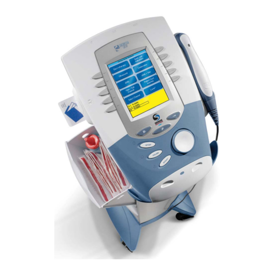
Senior Solutions™ Therapy System 3 NOMENCLATURE 3.1 SENIOR SOLUTIONS THERAPY SYSTEM A. Senior Solutions Therapy System The nomenclature graphic below, Figure 3.1, Refer to the respective pages of this section locates the major components of a two for specific nomenclature of the optional channel combination therapy system equipped modules. -
Page 13: Senior Solutions Combination Therapy System
3 NOMENCLATURE Senior Solutions™ Therapy System 3.1 SENIOR SOLUTIONS THERAPY SYSTEM (CONTINUED) B. Senior Solutions Therapy System The nomenclature graphics below, Figure 3.2, Know the components and their functions indicate the general locations of the exterior before performing any operation of or service to components of the Two Channel Senior the Senior Solutions Therapy System. -
Page 14: Senior Solutions
Know the components and their functions indicate the general locations of the exterior before performing any operation of or service components of the Senior Solutions Therapy to the Senior Solutions Therapy Two Channel Two Channel Electrotherapy System. Electrotherapy System. FIGURE 3.3... -
Page 15: Channel 3/4 Electrotherapy Module
The nomenclature graphics below, Figure 3.4, before performing any operation of or service indicate the general locations of the exterior to the Senior Solutions Therapy System Channel components of the Senior Solutions Therapy 3/4 Electrotherapy Module. System Channel 3/4 Electrotherapy Module. -
Page 16: Senior Solutions
1. NiMH Battery Module NOTE: The NiMH Battery Module is not operable unless it 2. Extended Front Access Panel is properly connected to a Senior Solutions Therapy 3. Module to System Mounting Holes System. 4. Module to System Feet Alignment Indents 5. -
Page 17: Senior Solutions Dual Channel Semg Module
Senior Solutions™ Therapy System 3 NOMENCLATURE 3.1 SENIOR SOLUTIONS THERAPY SYSTEM (CONTINUED) F. Senior Solutions Dual Channel sEMG Module The nomenclature graphics below, Figure 3.8, Know the components and their functions indicate the general locations of the exterior before performing any operation of or service... -
Page 18: G Senior Solutions Therapy System Cart
3 NOMENCLATURE Senior Solutions™ Therapy System 3.1 SENIOR SOLUTIONS THERAPY SYSTEM (CONTINUED) G. Senior Solutions Therapy System Cart The nomenclature graphics below, Figure 3.9, Know the components and their functions indicate the general locations of the exterior before performing any operation of or service to components of the Senior Solutions Therapy the Senior Solutions Therapy System Cart. -
Page 19: Senior Solutions Operator Remote Control
5. Manual Stimulation Button DECREASE STIMULATION INTENSITY 6. Channel 1 Decrease Intensity Button 7. Channel 1 Increase Intensity Button NOTE: The Senior Solutions Operator Remote Control is not operable unless it is properly connected to the Senior Solutions Therapy System. -
Page 20: Senior Solutions Therapy System Hardware And
3 NOMENCLATURE Senior Solutions™ Therapy System 3.2 SENIOR SOLUTIONS THERAPY SYSTEM HARDWARE AND SOFTWARE SYMBOL DEFINITIONS The symbol below are found on the system as Modules, and Accessories. well as within the software. These symbols are Know the symbols and their definitions before... -
Page 21: 4 Specifications
4.1 SENIOR SOLUTIONS THERAPY SYSTEM The specifications found in this section provide Refer to this section when performing physical details of the Senior Solutions Therapy troubleshooting, replacement, and repair of a System. This section also provides waveform Senior Solutions Therapy System, Modules, and specifications to aid in troubleshooting. -
Page 22: Electrotherapy Waveform Specifications
All waveforms, except High Voltage Pulsed Current troubleshooting. A waveform graphic from an (HVPC), of the Senior Solutions Therapy System have oscilloscope is also provided for clarification. a 200 mA current limit. Refer to this section when performing VMS™, VMS™... -
Page 23: Tens- Symmetrical Biphasic- Figure 4.4
4 SPECIFICATIONS Senior Solutions™ Therapy System 4.2 ELECTROTHERAPY WAVEFORM SPECIFICATIONS (CONTINUED) C. TENS- Symmetrical Biphasic- Figure 4.4 The Symmetrical Biphasic waveform has a short pulse duration and is capable of strong stimulation of nerve fibers in the skin and in muscle. This waveform is often used in portable muscle stimulation units, and some TENS devices. -
Page 24: Vms ™ - Figure 4.6
4 SPECIFICATIONS Senior Solutions™ Therapy System 4.2 ELECTROTHERAPY WAVEFORM SPECIFICATIONS (CONTINUED) E. VMS ™ - Figure 4.6 VMS is a symmetrical biphasic waveform with a 100 μsec interphase interval. Because the pulse is relatively short, the waveform has a low skin load, making it suitable for applications requiring high intensities, such as in muscle strengthening protocols. -
Page 25: Russian- Figure 4.8
4 SPECIFICATIONS Senior Solutions™ Therapy System 4.2 ELECTROTHERAPY WAVEFORM SPECIFICATIONS (CONTINUED) G. Russian- Figure 4.8 Russian Current is a sinusoidal waveform, delivered in bursts or series of pulses. This method was claimed by its author (Kots) to produce maximal muscle strengthening effects without significant discomfort to the patient. -
Page 26: Vms ™ Burst- Figure 4.11
Senior Solutions™ Therapy System 4 SPECIFICATIONS 4.2 ELECTROTHERAPY WAVEFORM SPECIFICATIONS (CONTINUED) J. VMS ™ Burst- Figure 4.11 VMS Burst is a symmetrical biphasic waveform delivered in a burst format. Because the pulse is relatively short, the waveform has a low skin load, making it suitable for applications requiring high intensities, such as in muscle strengthening protocols. - Page 27 Treatment Time ........................1-30 Mins Head Warming Feature The Head Warming feature of the Senior Solutions Combination Therapy System utilizes ultrasound output resulting in warming of the Sound Head to increase patient comfort.
-
Page 28: 5 Troubleshooting
No board level troubleshooting or field epair information is or will be provided by Chattanooga Group for field repair of the Senior Solutions Therapy System, Modules, or Accessories. Error messages in the range of 100 to 199 are... - Page 29 Warning Multimedia Card (MMC) not in system port. A. Properly insert the MMC card into the system port. B. Insert a known good MMC Card. If problem continues, contact dealer or Chattanooga Group for Service. Warning No valid channels are available for attempted treatment.
- Page 30 Number Message Warning Control Board Software upgrade warning. Upgrade Control Board Software to latest version. Contact dealer or Chattanooga Group for latest software upgrade and instructions. Warning Stim Board Main Software upgrade warning. Upgrade Stim Board Software to latest version. Contact dealer or Chattanooga Group for latest software upgrade and instructions.
- Page 31 5 TROUBLESHOOTING Senior Solutions™ Therapy System 5.1 THERAPY SYSTEM ERROR MESSAGES (CONTINUED) ERROR MESSAGES REQUIRING TECHNICAL ASSISTANCE 200299 Code Type Probable Cause Possible Remedies Number Message Error Error reading the system Real Time Clock (RTC) Replace Control Board Error Internal List Box Memory Error.
- Page 32 Senior Solutions™ Therapy System 5 TROUBLESHOOTING 5.1 THERAPY SYSTEM ERROR MESSAGES (CONTINUED) ERROR MESSAGES REQUIRING TECHNICAL ASSISTANCE 200299 Code Type Probable Cause Possible Remedies Number Message Error Error while performing a Software upgrade. A. Turn Therapy System Off and back On. Reattempt upgrade.
- Page 33 5 TROUBLESHOOTING Senior Solutions™ Therapy System 5.1 THERAPY SYSTEM ERROR MESSAGES (CONTINUED) CRITICAL ERRORS DEMANDING TECHNICAL SERVICE 300399 Code Type Probable Cause Possible Remedies Number Message Critical Error Stim Board not found on Power up. A. On Therapy System, make certain internal Ribbon Cable is seated on Stim PC Board and Control Board.
- Page 34 5 TROUBLESHOOTING Senior Solutions™ Therapy System 5.1 THERAPY SYSTEM ERROR MESSAGES (CONTINUED) CRITICAL ERRORS DEMANDING TECHNICAL SERVICE 300399 Code Type Probable Cause Possible Remedies Number Message Critical Error Error reading from Stim Board. A. On Therapy System, make certain internal Ribbon Cable is seated on Stim PC Board and Control Board.
- Page 35 5 TROUBLESHOOTING Senior Solutions™ Therapy System 5.1 THERAPY SYSTEM ERROR MESSAGES (CONTINUED) B. The information provided below is intended to aid in additional troubleshooting of the Senior Solutions Therapy System. Problem Probable Cause Possible Remedies Channel 3/4 Module, or NiMH 1.
-
Page 36: Therapy System Testing
The following information is intended to aid Dielectric Withstand (Hi-Pot) and ground in troubleshooting the major components resistance tester. of the Senior Solutions Therapy System to “board level” only. These tests are FACTORY NOTE: standard testing procedures and methods Adjust Dielectric Withstand tester to indicate... -
Page 37: Visual Inspection
5 TROUBLESHOOTING Senior Solutions™ Therapy System 5.3 VISUAL INSPECTION Visually inspect the Senior Solutions Therapy System. A visual inspection can, to an experienced technician, indicate possible abuse of the unit and internal problems. 5.4 LEAKAGE TESTS Conduct all necessary leakage tests as required per “Chapter 7 Electrical Equipment”... -
Page 38: Stimulator Test System Setup
5 TROUBLESHOOTING Senior Solutions™ Therapy System 5.6 STIMULATOR TEST SYSTEM SETUP The following tests for Stimulator Outputs will be performed on Channels 1 and 2. The performance of these same tests will apply to the Channel 3 and 4 Electrotherapy Module for four channel therapy systems. -
Page 39: Vms™ Mode Test
5 TROUBLESHOOTING Senior Solutions™ Therapy System 5.7 VMS™ MODE TEST A. VMS™ Mode Test Procedures Set Scope; Time- 100 μS, Channel- 50 V, and Trigger- DC. Press Electrotherapy Button. Press VMS Button and then press Edit Button. Press “Channel Mode” until “Co-Contracted”... -
Page 40: Interferential Mode Test
5 TROUBLESHOOTING Senior Solutions™ Therapy System 5.8 INTERFERENTIAL MODE TEST It is assumed that the unit is ready for tests as described in 5.6 parts A and B. If not, Set up unit per 5.6 parts A and B prior to performing tests. -
Page 41: Premodulated Mode Test
5 TROUBLESHOOTING Senior Solutions™ Therapy System 5.9 PREMODULATED MODE TEST Set up System per 5.6 parts A and B prior to performing test. A. Premodulated Mode Test Procedures Set Scope; Time- 2.50 mS, Channel- 20 V, and Trigger- DC. Press Electrotherapy button. -
Page 42: Russian Mode Test
5 TROUBLESHOOTING Senior Solutions™ Therapy System 5.10 RUSSIAN MODE TEST Set up System per 5.6 parts A and B prior to performing test. A. Russian Mode Test Procedures Set Scope; Time- 5 mS, Channel- 50 V, and Trigger- DC. Install Optional Patient Interrupt Switch. -
Page 43: Microcurrent Mode Test
5 TROUBLESHOOTING Senior Solutions™ Therapy System 5.11 MICROCURRENT MODE TEST Set up System per 5.6 parts A and B prior to performing test. Place ESTI-2 Load Switch in the 10 K Micro position only for the Microcurrent Mode Tests. See Figure LOAD SWITCH 5.10. -
Page 44: High Voltage Pulsed Current Hvpc Mode Test
5 TROUBLESHOOTING Senior Solutions™ Therapy System 5.12 HIGH VOLTAGE PULSED CURRENT HVPC MODE TEST PROPER NEGATIVE HIGH VOLT WAVEFORM Set up Unit per 5.6 parts A and B prior to performing tests. A. High Voltage Pulsed Current (HVPC) Mode Test Procedures Set Scope;... -
Page 45: Microcurrent Probe Mode Test
5 TROUBLESHOOTING Senior Solutions™ Therapy System 5.13 MICROCURRENT PROBE MODE TEST Set up Unit per 5.6 parts A and B prior to performing tests. Black Lead Wire for Channel 1 and Channel 3, and Microcurrent Probe with Probe Tips are required for this test. - Page 46 Senior Solutions™ Therapy System 5 TROUBLESHOOTING 5.13 MICROCURRENT PROBE MODE TEST (CONTINUED) B. MicroCurrent Probe Mode Test Results Unit performs as described in steps 5-7 and 10. Unit passed test. No Search Mode beep. Unit failed test. Try a known good Microcurrent Probe and repeat test.
-
Page 47: Ultrasound Tests
Applicator. 5.15 ULTRASOUND APPLICATOR IDENTIFICATION TEST FIGURE 5.18 NOTE: Use any Senior Solutions Therapy System Ultrasound Applicator for this test. A. Ultrasound Applicator Identification Test Procedures Without Applicator installed, turn unit on. Look at the “Ultrasound” channel icon at the lower left hand corner of screen. -
Page 48: Ultrasound Applicator Output Test
5 TROUBLESHOOTING Senior Solutions™ Therapy System 5.16 ULTRASOUND APPLICATOR OUTPUT TEST Perform this test using all available Senior Solutions Therapy System Applicators for the System being tested. A. Ultrasound Applicator Output Test Procedures Set up Ohmic Instruments UPM DT 10 or DT 100 Ultrasound Power Meter per Operator’s Instructions and fill test... -
Page 49: Ultrasound Duty Cycle Test
Senior Solutions™ Therapy System 5 TROUBLESHOOTING 5.17 ULTRASOUND DUTY CYCLE TEST This test is performed using only the 5 cm Senior Solutions Therapy System Applicator. A. Ultrasound Duty Cycle Test Procedures Set up Ohmic Instruments UPM DT 10 or DT 100 Ultrasound Power Meter per Operator’s Instructions and fill test... -
Page 50: Combo Operation Test
Applicator. Select Channel 2 and set up System per 5.6 parts A and B prior to performing tests. Connect Senior Solutions Therapy System 5 cm Applicator to the System. See Figure 5.25. Applicator LED will flash green five times. A. Combo Operation Test Procedures Set Scope;... -
Page 51: Semg And Semg + Electrical Stimulation Tests
Senior Solutions™ Therapy System 5.19 SEMG AND SEMG + ELECTRICAL STIMULATION TESTS ATTENUATOR SCHEMATIC This test is to be performed on the Senior Solutions Therapy System only with the sEMG Module properly 100K 1% installed. Perform this test on all Channels with sEMG. - Page 52 Senior Solutions™ Therapy System 5 TROUBLESHOOTING 5.19 SEMG AND SEMG + ELECTRICAL STIMULATION TESTS (CONTINUED) If icons are present, connect known good sEMG Lead Wire to Channels 1 and 2. See Figure 5.31. NOTE: Only one Channel at a time can be tested for sEMG.
- Page 53 5 TROUBLESHOOTING Senior Solutions™ Therapy System 5.19 SEMG AND SEMG + ELECTRICAL STIMULATION TESTS (CONTINUED) 7. Make certain the Audio Signal Generator is set up per 5.19, part B, steps 1, a) through 1, g). Connect the Audio Signal Generator Test Leads from the Generator...
- Page 54 5 TROUBLESHOOTING Senior Solutions™ Therapy System 5.19 SEMG AND SEMG + ELECTRICAL STIMULATION TESTS (CONTINUED) D. sEMG + STIM Tests To Check Stim output, conduct the Electrical Stimulator Tests as explained in 5.6 through 5.13. Set up Signal Generator and Attenuator as described in 5.19, part B.
-
Page 55: Nimh Battery Module Checks
5 TROUBLESHOOTING Senior Solutions™ Therapy System 5.20 NIMH BATTERY MODULE CHECKS The following checks for the NiMH Battery Module are to check for possible damage to the Battery Cells and proper connections within the module and module to System connection. - Page 56 5 TROUBLESHOOTING Senior Solutions™ Therapy System Using the Flat Blade Screwdriver, carefully release the tabs retaining the top plate in position. It will be necessary to lift with one hand while releasing the tabs with the Screwdriver. See Figure 5.38.
-
Page 57: 6 Removal/Replacement
Channels 1 and 2. The sEMG Module will not interfere with installation of a Module to the Therapy System. RIBBON CABLE LEAVE SEMG REMOVE IN PLACE Be careful to not disconnect the Ribbon Cable from LABEL the Senior Solutions Therapy System. FIGURE 6.4... - Page 58 6 REMOVAL/REPLACEMENT Senior Solutions™ Therapy System BLUE STRIP DISCONNECT THE SYSTEM FROM THE POWER SOURCE (OUTLET OR REMOVE BATTERY MODULE IF INSTALLED) BEFORE ATTEMPTING ANY MAINTENANCE, INSTALLATION, REMOVAL, OR REPLACEMENT PROCEDURES TO PREVENT ELECTRICAL SHOCK AND POSSIBLE DAMAGE TO SYSTEM.
- Page 59 6 REMOVAL/REPLACEMENT Senior Solutions™ Therapy System DISCONNECT THE SYSTEM FROM THE POWER SOURCE (OUTLET OR REMOVE BATTERY MODULE IF INSTALLED) BEFORE ATTEMPTING ANY MAINTENANCE, INSTALLATION, REMOVAL, OR REPLACEMENT PROCEDURES TO PREVENT ELECTRICAL SHOCK AND POSSIBLE DAMAGE TO SYSTEM. Holding Module to system, position both on one side and secure the Module to the System with four 4 mm x 20 mm Screws.
- Page 60 Chattanooga Group Technical Support immediately. DO NOT USE THE SYSTEM until all necessary repairs are made by a Technician certified by Chattanooga Group. If use is attempted before repairs are made, the system FIGURE 6.11...
-
Page 61: Semg Module Installation And Removal
6 REMOVAL/REPLACEMENT Senior Solutions™ Therapy System EMG MODULE INSTALLATION AND REMOVAL DISCONNECT THE SYSTEM FROM THE POWER SOURCE (OUTLET OR REMOVE BATTERY MODULE IF INSTALLED) BEFORE ATTEMPTING ANY MAINTENANCE, INSTALLATION, REMOVAL, OR REPLACEMENT PROCEDURES TO PREVENT ELECTRICAL SHOCK AND POSSIBLE DAMAGE TO SYSTEM. - Page 62 6 REMOVAL/REPLACEMENT Senior Solutions™ Therapy System DISCONNECT THE SYSTEM FROM THE POWER SOURCE (OUTLET OR REMOVE BATTERY MODULE IF INSTALLED) BEFORE ATTEMPTING ANY MAINTENANCE, INSTALLATION, REMOVAL, OR REPLACEMENT PROCEDURES TO PREVENT ELECTRICAL SHOCK AND POSSIBLE DAMAGE TO SYSTEM. Position the Surface EMG Module so that...
- Page 63 Chattanooga Group Technical Support immediately. DO NOT USE THE SYSTEM until all necessary repairs are made by a Technician certified by Chattanooga Group. If use is attempted before repairs are made, the system FIGURE 6.16...
-
Page 64: Therapy System Separating Top & Bottom
6 REMOVAL/REPLACEMENT Senior Solutions™ Therapy System 6.4 THERAPY SYSTEM SEPARATING REMOVE 4 SCREWS TOP & BOTTOM DISCONNECT THE SYSTEM FROM THE POWER SOURCE (OUTLET OR REMOVE BATTERY MODULE IF INSTALLED) BEFORE ATTEMPTING ANY MAINTENANCE, INSTALLATION, REMOVAL, OR REPLACEMENT PROCEDURES TO PREVENT ELECTRICAL SHOCK AND POSSIBLE DAMAGE TO SYSTEM. - Page 65 6 REMOVAL/REPLACEMENT Senior Solutions™ Therapy System DISCONNECT THE SYSTEM FROM THE POWER SOURCE (OUTLET OR REMOVE BATTERY MODULE IF INSTALLED) BEFORE ATTEMPTING ANY MAINTENANCE, INSTALLATION, REMOVAL, OR REPLACEMENT PROCEDURES TO PREVENT ELECTRICAL SHOCK AND POSSIBLE DAMAGE TO SYSTEM. Lay System Top on the edge and disconnect the remaining harnesses from the Control Board.
-
Page 66: Therapy System Fan
Senior Solutions™ Therapy System 6 REMOVAL/REPLACEMENT 6.5 THERAPY SYSTEM FAN DISCONNECT THE SYSTEM FROM THE POWER REMOVE SOURCE (OUTLET OR REMOVE BATTERY MODULE IF SCREWS INSTALLED) BEFORE ATTEMPTING ANY MAINTENANCE, INSTALLATION, REMOVAL, OR REPLACEMENT PROCEDURES TO PREVENT ELECTRICAL SHOCK AND POSSIBLE DAMAGE TO SYSTEM. -
Page 67: Therapy System Control Board Assembly
6 REMOVAL/REPLACEMENT Senior Solutions™ Therapy System 6.6 THERAPY SYSTEM CONTROL BOARD ASSEMBLY CONTRAST KNOB DISCONNECT THE SYSTEM FROM THE POWER SOURCE (OUTLET OR REMOVE BATTERY MODULE IF INSTALLED) BEFORE ATTEMPTING ANY MAINTENANCE, INSTALLATION, REMOVAL, OR REPLACEMENT PROCEDURES TO PREVENT ELECTRICAL SHOCK AND POSSIBLE DAMAGE TO SYSTEM. -
Page 68: Therapy System Keymat Assembly
6 REMOVAL/REPLACEMENT Senior Solutions™ Therapy System 6.7 THERAPY SYSTEM KEYMAT ASSEMBLY DISCONNECT THE SYSTEM FROM THE POWER REMOVE SOURCE (OUTLET OR REMOVE BATTERY MODULE IF RETAINING INSTALLED) BEFORE ATTEMPTING ANY MAINTENANCE, SCREWS INSTALLATION, REMOVAL, OR REPLACEMENT PROCEDURES TO PREVENT ELECTRICAL SHOCK AND POSSIBLE DAMAGE TO SYSTEM. -
Page 69: Therapy System Connector Board
6 REMOVAL/REPLACEMENT Senior Solutions™ Therapy System 6.8 THERAPY SYSTEM CONNECTOR BOARD DISCONNECT THE SYSTEM FROM THE POWER SOURCE (OUTLET OR REMOVE BATTERY MODULE IF INSTALLED) BEFORE ATTEMPTING ANY MAINTENANCE, INSTALLATION, REMOVAL, OR REPLACEMENT PROCEDURES TO PREVENT ELECTRICAL SHOCK AND POSSIBLE DAMAGE TO SYSTEM. -
Page 70: Therapy System Ultrasound Board Combination Systems Only
6 REMOVAL/REPLACEMENT Senior Solutions™ Therapy System 6.9 THERAPY SYSTEM ULTRASOUND BOARD COMBINATION SYSTEMS ONLY DISCONNECT THE SYSTEM FROM THE POWER SOURCE (OUTLET OR REMOVE BATTERY MODULE IF INSTALLED) BEFORE ATTEMPTING ANY MAINTENANCE, INSTALLATION, REMOVAL, OR REPLACEMENT PROCEDURES TO PREVENT ELECTRICAL SHOCK AND POSSIBLE DAMAGE TO SYSTEM. -
Page 71: Therapy System Stim Board Channels 1/2
6 REMOVAL/REPLACEMENT Senior Solutions™ Therapy System 6.10 THERAPY SYSTEM STIM BOARD CHANNELS 1/2 SLOT 90° TO LOCKED INDICATOR DISCONNECT THE SYSTEM FROM THE POWER SOURCE (OUTLET OR REMOVE BATTERY MODULE IF INSTALLED) BEFORE ATTEMPTING ANY MAINTENANCE, INSTALLATION, REMOVAL, OR REPLACEMENT PROCEDURES TO PREVENT ELECTRICAL SHOCK AND POSSIBLE DAMAGE TO SYSTEM. -
Page 72: Therapy System Power Supplies
6 REMOVAL/REPLACEMENT Senior Solutions™ Therapy System 6.11 THERAPY SYSTEM POWER SUPPLIES NOTE: The Senior Solutions Therapy System incorporates two different Power Supply configurations: Combination Therapy System- Two Power Supplies, one 75 Watt for Ultrasound Power and one 100 Watt to power the rest of the system. - Page 73 6 REMOVAL/REPLACEMENT Senior Solutions™ Therapy System MAINS WIRING DISCONNECT THE SYSTEM FROM THE POWER HARNESS SOURCE (OUTLET OR REMOVE BATTERY MODULE IF INSTALLED) BEFORE ATTEMPTING ANY MAINTENANCE, INSTALLATION, REMOVAL, OR REPLACEMENT PROCEDURES TO PREVENT ELECTRICAL SHOCK AND PLIERS NOT POSSIBLE DAMAGE TO SYSTEM.
-
Page 74: Channel 3/4 Electrotherapy Module
6 REMOVAL/REPLACEMENT Senior Solutions™ Therapy System 6.12 CHANNEL 3/4 ELECTROTHERAPY MODULE CONNECTOR BOARD DISCONNECT THE SYSTEM FROM THE POWER SOURCE (OUTLET OR REMOVE BATTERY MODULE IF INSTALLED) BEFORE ATTEMPTING ANY MAINTENANCE, INSTALLATION, REMOVAL, OR REPLACEMENT PROCEDURES TO PREVENT ELECTRICAL SHOCK AND POSSIBLE DAMAGE TO SYSTEM. -
Page 75: Channel 3/4 Electrotherapy Module Stim Board
6 REMOVAL/REPLACEMENT Senior Solutions™ Therapy System 6.13 CHANNEL 3/4 ELECTROTHERAPY MODULE STIM BOARD DISCONNECT THE SYSTEM FROM THE POWER SOURCE (OUTLET OR REMOVE BATTERY MODULE IF INSTALLED) BEFORE ATTEMPTING ANY MAINTENANCE, INSTALLATION, REMOVAL, OR REPLACEMENT PROCEDURES TO PREVENT ELECTRICAL SHOCK AND POSSIBLE DAMAGE TO SYSTEM. -
Page 76: Mounting And Dismounting Therapy System And Therapy System Cart
Senior Solutions™ Therapy System 6 REMOVAL/REPLACEMENT 6.14 MOUNTING AND DISMOUNTING THERAPY SYSTEM AND THERAPY SYSTEM CART DISCONNECT THE SYSTEM FROM THE POWER SOURCE (OUTLET OR REMOVE BATTERY MODULE IF INSTALLED) BEFORE ATTEMPTING ANY MAINTENANCE, INSTALLATION, REMOVAL, OR REPLACEMENT PROCEDURES TO PREVENT ELECTRICAL SHOCK AND POSSIBLE DAMAGE TO SYSTEM. -
Page 77: 7 General Maintenance
7.3 FIELD SERVICE A. All field service procedures as described in this Service Manual for the Senior Solutions Therapy System must be performed by a Service Technician certified by Chattanooga Group. -
Page 78: 8 Ultrasound Calibration
A. Tools and Equipment Required SOFTWARE VERSION 2.0 OR Senior Solutions Combination Therapy ABOVE System and all Senior Solutions Ultrasound Applicators associated with the System being serviced. Ohmic Instruments UPM DT 10 or DT 100 Ultrasound Power Meter, set to “watts”. -
Page 79: 9 Parts
Senior Solutions™ Therapy System 9 PARTS TOP TO BOTTOM ASSEMBLY TOP ASSEMBLY BOTTOM ASSEMBLY ITEM PART DESCRIPTION NUMBER NUMBER REQ'D 27159 Bottom Assembly to Top Assembly Ribbon Cable 27306 Rear Access Panel 27138 Screw, M3 x 16 mm 27029 Front Access Panel... -
Page 80: Combination System Base Assembly
9 PARTS Senior Solutions™ Therapy System COMBINATION SYSTEM BASE ASSEMBLY STIM & ULTRASOUND BOARD ASSEMBLY SEE PAGE 84 ITEM PART DESCRIPTION NUMBER NUMBER REQ'D 27022 Mains Harness Clip 27276 Main Power Switch 27277 Mains Power Input Connector 27010 Applicator Holder... -
Page 81: Combination Stim & Ultrasound Pc Board Assembly
9 PARTS Senior Solutions™ Therapy System COMBINATION STIM & ULTRASOUND PC BOARD ASSEMBLY ITEM PART DESCRIPTION NUMBER NUMBER REQ'D 27055 Ultrasound PC Board 27161 Ultrasound to Stim Header 27160 PC Board Stand Off 27057 Stim PC Board... -
Page 82: Top Housing Assembly
Senior Solutions™ Therapy System 9 PARTS TOP HOUSING ASSEMBLY CONTROL BOARD ASSEMBLY SEE PAGE 63, 79, 81 ITEM PART DESCRIPTION NUMBER NUMBER REQ'D 28122 Top Housing (Blue) 28400 Lens (Senior Solutions) 27026 Left Keymat 27027 Right Keymat 27051 Keymat PC Board... -
Page 83: Senior Solutions Control Board Assembly
9 PARTS Senior Solutions™ Therapy System SENIOR SOLUTIONS THERAPY SYSTEM CONTROL BOARD ASSEMBLY ITEM PART DESCRIPTION NUMBER NUMBER REQ'D 27093 Color Display Mounting Bracket/Spacer 27162 Color Display 27012 Contrast Knob (Not Functional) 27053 Color Control PC Board 27137 Screw, M4 x 8 mm... -
Page 84: Channel 3/4 Electrotherapy Module Assembly
9 PARTS Senior Solutions™ Therapy System CHANNEL 3/4 ELECTROTHERAPY MODULE ASSEMBLY ITEM PART DESCRIPTION NUMBER NUMBER REQ'D 27015 Module Top 27353 Stim Board to Ribbon Cable Header 27057 Stim PC Board 27016 Module Bottom Housing 27150 Feet 27061 Channel 3/4 Stim Connector PC Board... -
Page 85: 10 Schematics
10 SCHEMATICS Senior Solutions™ Therapy System... - Page 86 10 SCHEMATICS Senior Solutions™ Therapy System...
- Page 87 10 SCHEMATICS Senior Solutions™ Therapy System...
-
Page 88: Ultrasound Pc Board
10 SCHEMATICS Senior Solutions™ Therapy System... - Page 89 10 SCHEMATICS Senior Solutions™ Therapy System...
- Page 90 10 SCHEMATICS Senior Solutions™ Therapy System...
-
Page 91: Senior Solutions Therapy System- Stim Board
10 SCHEMATICS Senior Solutions™ Therapy System... - Page 92 10 SCHEMATICS Senior Solutions™ Therapy System...
- Page 93 10 SCHEMATICS Senior Solutions™ Therapy System...
- Page 94 10 SCHEMATICS Senior Solutions™ Therapy System...
- Page 95 10 SCHEMATICS Senior Solutions™ Therapy System...
- Page 96 10 SCHEMATICS Senior Solutions™ Therapy System...
- Page 97 10 SCHEMATICS Senior Solutions™ Therapy System...
- Page 98 10 SCHEMATICS Senior Solutions™ Therapy System...
- Page 99 10 SCHEMATICS Senior Solutions™ Therapy System...
- Page 100 10 SCHEMATICS Senior Solutions™ Therapy System...
-
Page 101: Senior Solutions Therapy System- Connector Board
10 SCHEMATICS Senior Solutions™ Therapy System... -
Page 102: Electrotherapy Module Connector Board
10 SCHEMATICS Senior Solutions™ Therapy System... -
Page 103: Senior Solutions Therapy System- Power Supplies
10 SCHEMATICS Senior Solutions™ Therapy System... - Page 104 10 SCHEMATICS Senior Solutions™ Therapy System...
-
Page 107: Senior Solutions Therapy System
Senior Solutions™ Therapy System SENIOR SOLUTIONS THERAPY SYSTEM Chattanooga Group, a division of Encore Medical, L.P., ("Company") warrants that the Senior Solutions Therapy System, Channel 3/4 Electrotherapy Module, and sEMG Module ("Products") are free of defects in material and workmanship. This warranty shall remain in effect for two years (24 months) from the date of original consumer purchase. - Page 108 Moving Rehabilitation Foward™ ISO 13485 CERTIFIED 4717 Adams Road P.O. Box 489 Hixson, TN 37343 U.S.A. 1-423-870-2281 U.S.A. 1-800-592-7329 U.S.A. 1-423-875-5497 U.S.A. FAX chattgroup.com © 2008 Encore Medical, L.P. *28426* 28426B...
Need help?
Do you have a question about the SENIOR SOLUTIONS and is the answer not in the manual?
Questions and answers