A&D Omniace RA3100 Instruction Manual
Hide thumbs
Also See for Omniace RA3100:
- Instruction manual (340 pages) ,
- Simple instruction manual (76 pages) ,
- Instruction manual (60 pages)
Table of Contents
Advertisement
Quick Links
Advertisement
Table of Contents

Related Manuals for A&D Omniace RA3100


Summary of Contents for A&D Omniace RA3100
- Page 1 RA3100 Omniace Instruction Manual 1WMPD4004444B...
- Page 2 CAUTION (1) Turn off the power when the operation is abnormal. If it is impossible to trace the causes of an abnormal operation, please contact our sales representative. (2) The contents of this manual are subject to change without notice. (3) This manual is copyrighted with all rights reserved.
-
Page 3: Introduction
Introduction We thank you for your purchase of our data acquisition product OMNIACE RA3100 (hereinafter "the RA3100" or "this product"). This instruction manual explains cautions and methods for handling the RA3100 and its optional input modules. Please read this manual before operating this instrument. -
Page 4: Examining Contents In Package
Examining Contents in Package Examining Contents in Package When Opening Package When opening the package in a warm room during the cold season, open the package after it has reached room temperature to avoid any operational failure due to condensation on the surface of the product. -
Page 5: To Safely Use Products
To Safely Use Products To Safely Use Products Safety Measures - Warnings and Cautions This product is designed and tested to conform to the EN61010 standard. The product is manufactured with safety in mind. However, accidents may occur due to misuse by the user. - Page 6 To Safely Use Products WARNING Protective Grounding Be sure to ground this product before supplying power. Grounding is necessary to use this product safely, as well as to protect the user and peripheral equipment from injury or damage. Be sure to observe the following instructions: The AC power cable included with this product contains a ground lead.
- Page 7 To Safely Use Products CAUTION Caution in Handling When using this product, always follow the precautions below. Improper handling may lead to erroneous operations and damages. Users who are not familiar with the operation of this product should avoid using it. Use this product at locations that satisfy the overvoltage requirement, the Category II (CAT II) of the safety standard for electrical measurement instruments in EN61010-1.
- Page 8 To Safely Use Products CAUTION This product uses an electrostatic capacitive touch panel. Press the touch panel gently with your bare fingertip. The touch screen may not react if you are wearing gloves. Also do not use a sharp object or push with higher pressure than necessary. Pressing three or more locations at once may cause misoperations.
-
Page 9: Disposing Of The Used Product
To Safely Use Products CAUTION Windows 10 IoT This product adopts Windows 10 IoT as its operating system. Please read and understand the following instructions carefully before use. License The Windows 10 IoT operating system used in this product is provided with a license for embedded use only. -
Page 10: Symbols In This Manual
Symbols in This Manual Symbols in This Manual Terms and symbols used in this manual denote as follows. This indicates a condition or practice that could result in personal injury or loss of life, or may result in light injury or physical damage if this equipment is misused due WARNING to neglect of a Warning. -
Page 11: Warranty
Warranty Warranty Warranty - General We ship our products after conducting quality control, which covers from design to manufacturing. It is, however, possible that failures may occur in the products. If the product does not operate correctly, please make a check of the power supply, cable connections, or other conditions before returning this product to us. -
Page 12: Table Of Contents
CONTENTS CONTENTS INTRODUCTION ............................... 3 EXAMINING CONTENTS IN PACKAGE ......................4 TO SAFELY USE PRODUCTS .......................... 5 DISPOSING OF THE USED PRODUCT ......................9 SYMBOLS IN THIS MANUAL .......................... 10 WARRANTY ..............................11 NAME AND FUNCTION OF EACH BLOCK ................17 1.1. - Page 13 CONTENTS 5.3. Pre-Trigger ..........................50 5.3.1. Pre-Trigger Setup ......................... 50 5.4. Start Trigger ..........................51 5.4.1. Start Trigger Setup ....................... 51 MEASURING INPUT SIGNALS ....................52 6.1. State Transition of Main Unit Operation ................... 52 6.2. Monitor Display and Pen Recording ..................53 6.2.1.
- Page 14 CONTENTS 8.1.1. Recording ........................... 101 8.1.2. Channel List ........................102 8.1.3. Sheet Setup ........................105 8.1.4. Printer ..........................108 8.2. Main Unit Setup ........................111 8.2.1. Record management ......................111 8.2.2. Export - Backing Up Recorded Data .................. 113 8.2.3. Import - Reading Backup Data ...................
- Page 15 CONTENTS 9.6.5. Measurement Setup ......................152 9.6.6. Reference Materials ......................153 9.6.7. Options ..........................157 APPENDIX ..........................160 10.1. Sampling Data Format ......................160 10.1.1. Normal Sampling ........................ 160 10.1.2. P-P Sampling ........................160 10.2. Sampling ..........................161 10.2.1. Internal Sampling........................ 161 10.2.2.
- Page 16 CONTENTS 12.2.9. Setup/Record management ....................183 12.2.10. Interface Specifications ...................... 184 12.2.11. Communication Setup ......................185 12.2.12. Other Setup (Maintenance/Operation History/Version Management) ........ 186 12.3. Module Specifications ......................187 12.3.1. Two Channel Voltage Module (RA30-101) ................. 187 12.3.2. Four Channel Voltage Module (RA30-102) ................ 188 12.3.3.
-
Page 17: Name And Function Of Each Block
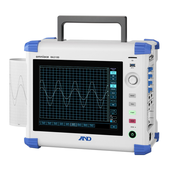
1.Name and Function of Each Block – 1.1.Name of Each Block Name and Function of Each Block This product consists of the following blocks. 1.1. Name of Each Block Front view Handle (retractable) SD card slot Display Block Operation panel Power switch Corner pad Screen lock... - Page 18 1.Name and Function of Each Block – 1.1.Name of Each Block Top view Handle (retractable) Rear view Stand 1WMPD4004444B...
-
Page 19: Display Block
1.Name and Function of Each Block – 1.2.Display Block 1.2. Display Block This product has a TFT color LCD display with touch panel. The LCD displays the waveform monitor and setup keys, and users can configure setup by directly touching the panel. Waveform monitor Side menu Scroll the waveform... -
Page 20: Operation Panel
1.Name and Function of Each Block – 1.3.Operation Panel 1.3. Operation Panel (1) SD card slot Used to save recorded data to an SD memory card, etc. (2) USB Used to save recorded data to USB memory, etc. in the same manner as to an SD memory card. -
Page 21: Interface Block
1.Name and Function of Each Block – 1.4.Interface Block 1.4. Interface Block (1) Key lock Disables the operation panel keys to prevent misoperations. (2) Screen lock Disables the touch panel keys to prevent misoperations. (3) USB Used to save recorded data, etc. Supports USB 3.0. (4) LAN Used to perform remote control from an external PC via LAN. -
Page 22: Screen And Setup Menu
1.Name and Function of Each Block – 1.6.Screen and Setup Menu 1.6. Screen and Setup Menu Waveform monitor Side menu Control Bar 1.6.1. Side menu (1) Time: Displays the current time (2) MEASURE/PLAYBACK: Switches the displayed waveform MEASURE: Displays the current input waveform. PLAYBACK: Displays the playback waveform of the saved data. -
Page 23: Control Bar
1.Name and Function of Each Block – 1.6.Screen and Setup Menu 1.6.2. Control Bar The control bar provides a menu for the functions frequently used with the waveform monitor, such as waveform display control of sampling, etc., thumbnail display, cursor display, and the pen recorder function. - Page 24 1.Name and Function of Each Block – 1.6.Screen and Setup Menu Control bar when playback Touch the PLAYBACK key on the side menu to enter the playback mode and switch the control bar to the menu for playback. (1) Sampling speed : Displays the sampling speed of the recorded data.
-
Page 25: Pre-Measurement Procedures
2.Pre-Measurement Procedures – 2.1.Before Switching On the Power Pre-Measurement Procedures 2.1. Before Switching On the Power The preparations for using this product and the cautions are explained below. 2.1.1. Installation and Usage Environment Use this product on a flat, level surface. When using the printer, install it so that the recording paper is level as indicated in the figure on the right. - Page 26 2.Pre-Measurement Procedures – 2.1.Before Switching On the Power WARNING Module installation/removal and replacement must be performed after disconnecting all the cables connected to the module, turning off the power switch of the main unit, and disconnecting the power cable. Insert the module along the guide rails, and securely fix the two knurled screws with a Phillips head screwdriver.
-
Page 27: Installing Optional Modules
2.Pre-Measurement Procedures – 2.1.Before Switching On the Power 2.1.2. Installing Optional Modules Installation Procedure Step 1. Turn the power OFF. Step 2. Disconnect the power cable. Step 3. Grip the handles on both edges and insert the module straight in along the guide rails. The module type should be on the operation panel side. -
Page 28: Paper Loading
2.Pre-Measurement Procedures – 2.1.Before Switching On the Power 2.1.3. Paper Loading The procedure for loading recording paper to the printer block is indicated below. Load the recording paper to this product. There are two types of recording paper: paper rolls and Z-fold paper. - Page 29 2.Pre-Measurement Procedures – 2.1.Before Switching On the Power Step 2. Open the printer cover by raising the lever of the printer block. Pull the lever upwards. Recording paper guide (the U-shaped groove) Platen roller (black roller) Recording paper outlet Step 3. Load the paper following the guide of the product, and press the paper holders into the guide until a click is heard.
- Page 30 2.Pre-Measurement Procedures – 2.1.Before Switching On the Power Loading Z-fold Paper (Recording Paper) To use Z-fold paper (YPS112), a Z-fold paper case (RA30-551, sold separately) is required. <Z-fold paper> YPS112 Length: 200 m Folded width: 30 cm To indicate how much paper is remaining, a page number (669 to 000) is printed on each page. <Z-fold paper box>...
- Page 31 2.Pre-Measurement Procedures – 2.1.Before Switching On the Power Step 2-2. Place the paper in the stock box with the thermally sensitive side (the side with blue numbers printed on the edges) facing up. Thermal sensitive side Z-fold paper stock box Step 2-3.
- Page 32 2.Pre-Measurement Procedures – 2.1.Before Switching On the Power Step 5. Attach the Z-fold paper adapter to the recording paper guide of the printer cover. Insert the Z-fold paper adapter with paper threaded into the recording paper guide (the U-shaped groove) of this product with the center knob facing down, and push it in until it clicks.
-
Page 33: Turning The Power On/Off
2.Pre-Measurement Procedures – 2.2.Turning the Power On/Off 2.2. Turning the Power On/Off 2.2.1. Connecting the AC Power Cable Be sure to check the following points before connecting the AC power cable to this product. Make sure that the power supply matches the rating indicated on the rating plate attached to this product. -
Page 34: Confirming Normal Startup
2.Pre-Measurement Procedures – 2.2.Turning the Power On/Off Step 4. Turn the power switch of the product on. When the Power switch on the operation panel of the product is turned on, the green LED lights up and the power turns on. NOTE Standby current flows to this product when the AC power cable is connected to the power outlet. -
Page 35: Flow Of Measurement
3.Flow of Measurement – 3.1.Flow of Measurement Flow of Measurement This product records and play back input signals following the procedures described below. 3.1. Flow of Measurement Perform the check "Chapter Confirm that this product has been set in a safe place, and that all the 2"... -
Page 36: Configuring Measurement
4.Configuring Measurement – 4.1.Reducing the Input Sensitivity and Connecting the Input Cable Configuring Measurement 4.1. Reducing the Input Sensitivity and Connecting the Input Cable Step 1. The input signal can be displayed and checked in real-time by switching the MEASURE/ PLAYBACK key on the side menu... - Page 37 4.Configuring Measurement – 4.1.Reducing the Input Sensitivity and Connecting the Input Cable Step 5. Tap the tab in the channel setup sub menu to change the displayed channel. Step 6. To change the display slot of the input module, swipe the channel setup sub menu left or right, or tap the <...
-
Page 38: Setting The Input Channel
4.Configuring Measurement – 4.2.Setting the Input Channel 4.2. Setting the Input Channel 4.2.1. Channel setup sub menu (for RA30-101) (1) Slot number, input module type (2) Change slot: You can change the display slot by swiping this sub menu left or right or tapping the left <... -
Page 39: Setup The Input Channels
4.Configuring Measurement – 4.2.Setting the Input Channel (17) Zero adjust: Cancels the input offset of the input channel. Execute zero cancellation to perform more accurate measurement. (18) Available measurement range/measurement value: Displays the current available measurement range and measurement value. 4.2.2. - Page 40 4.Configuring Measurement – 4.2.Setting the Input Channel Description of Step 2 (setting the measurement range) The input sensitivity can be changed in Meas. range in the channel setup sub menu. The value displayed for the measurement range (RANGE) indicates the input (measurement) maximum value and corresponds to 10 div on the waveform monitor.
- Page 41 4.Configuring Measurement – 4.2.Setting the Input Channel Description of Step 4 (setting graph division) (procedure on page 39) "Graph" refers to the area in the Y-T waveform monitor where a channel waveform can be displayed. The graph area can be divided into 1 to 18 graphs. →...
- Page 42 4.Configuring Measurement – 4.2.Setting the Input Channel Description of Step 5 (setting the display range and display position (waveform display area)) (procedure on page 39) When displaying multiple channels, it may be difficult to recognize them because the waveforms overlap. Reducing the input sensitivity in the measurement range decreases the amplitude and changes the display position, which can stop the waveforms from overlapping and make them easier to recognize, but this also reduces the resolution of the data.
- Page 43 4.Configuring Measurement – 4.2.Setting the Input Channel Description of Step 6 (setting the display maximum and display minimum (waveform display scale)) (procedure on page 39) If the amplitude of the input signal is smaller than the set range, the signal change may be hard to recognize.
-
Page 44: Selecting The Recording Method
4.Configuring Measurement – 4.3.Selecting the Recording Method 4.3. Selecting the Recording Method Select the recording method, depending on whether to save the measurement data to a file. 4.3.1. Recording to Recording Paper Only Perform "pen recording" to record to recording paper only, without saving a file. "6.2.2. -
Page 45: Recording Setup
4.Configuring Measurement – 4.4.Recording Setup 4.4. Recording Setup 4.4.1. Setup the Sampling Speed An image of the waveform recorded on the selected recording device (PRINTER, SSD, or MEMORY) is displayed on the waveform monitor. The sampling speed of the image waveform recorded on the selected recording device is displayed on the left edge of the control bar. -
Page 46: Sampling Speed Of Recording Device
4.Configuring Measurement – 4.4.Recording Setup 4.4.2. Sampling Speed of Recording Device There are three types of recording device (PRINTER, SSD, and MEMORY). The sampling speed setting range and characteristics of each device are indicated below. 100 ms/div (1 kS/s) 10 min/div (10 S/min), Setting range EXT. -
Page 47: Trigger Setup
5.Trigger Setup – 5.1.Trigger Types Trigger Setup 5.1. Trigger Types This product has two types of triggers: Memory triggers for memory recording and Start triggers for starting recording. 5.2. Memory trigger Memory trigger is a signal for enabling memory recording, and is occurred when the trigger conditions of the channel specified in the trigger source are established. - Page 48 5.Trigger Setup – 5.2.Memory trigger Step 3. Up to 18 trigger sources ( T1 T18 ) can be set. Tap the number of the trigger source to set to display the details screen. (1) Trigger menu selection: Switches between the Memory trigger, Start trigger, or Memory block menu (2) Channel: Selects the TRIGn source channel.
- Page 49 5.Trigger Setup – 5.2.Memory trigger Change threshold with rotary knob Trigger source Channel signal Trigger point The threshold (trigger level) is displayed in red Press and hold the threshold, and change the threshold with the numeric keys When the trigger direction is set to UP, the trigger point is when the input signal exceeds the trigger level Description of trigger source...
-
Page 50: Pre-Trigger
5.Trigger Setup – 5.3.Pre-Trigger Description of trigger source (5) Filter (Setting on page Trigger filter The trigger filter function ensures that a trigger is detected when the trigger conditions are met for a specified period of time, in order to prevent erroneous trigger detection due to noise or chattering in the signal near the trigger level. -
Page 51: Start Trigger
5.Trigger Setup – 5.4.Start Trigger 5.4. Start Trigger The start trigger function starts recording when the trigger conditions are established for the channel specified in the trigger source. Press the START key on the operation panel to put the product in the standby state. -
Page 52: Measuring Input Signals
6.Measuring Input Signals – 6.1.State Transition of Main Unit Operation Measuring Input Signals 6.1. State Transition of Main Unit Operation This product is divided into three states according to the operation state: measure, record, and playback. PRINT key can also be pressed in the measurement state to perform pen recording (real-time waveform printing).The START key can also be pressed in the measure state to perform printer recording, SSD recording, and memory recording. -
Page 53: Monitor Display And Pen Recording
6.Measuring Input Signals – 6.2.Monitor Display and Pen Recording 6.2. Monitor Display and Pen Recording 6.2.1. Monitor Display Function Tap the recording device selection in the side menu to display the image waveform recorded on the selected device on the waveform monitor. Printer recording SSD recording Memory recording... - Page 54 6.Measuring Input Signals – 6.2.Monitor Display and Pen Recording Pausing Tap the PAUSE key on the waveform monitor to stop the monitor. In this state, you can pinch in (reduce) or pinch out (expand) the waveform on the waveform monitor. You can also use one finger to drag the screen up, down, left, or right to move the display area.
- Page 55 6.Measuring Input Signals – 6.2.Monitor Display and Pen Recording Sampling speed Use the Sampling speed key on the left edge of the control bar to change the sampling speed according to the recording device. Set the optimal sampling speed while viewing the monitor waveform. Set the optimal sampling speed while viewing the monitor waveform.
-
Page 56: Pen Recording
6.Measuring Input Signals – 6.2.Monitor Display and Pen Recording 6.2.2. Pen Recording Pen recording enables direct waveform printing to the recording paper without saving the measurement data. This enables single-touch simple and certain waveform recording like a conventional pen recorder. Pen Recording Press the PRINT... - Page 57 6.Measuring Input Signals – 6.2.Monitor Display and Pen Recording Setting the Chart Speed Keys Follow the procedure below to set the chart speed keys. Step 1. Tap the SETUP key on the side menu to display the setup menu. Step 2. Printer in [■...
-
Page 58: Setup And Printing Annotations
6.Measuring Input Signals – 6.2.Monitor Display and Pen Recording 6.2.3. Setup and Printing Annotations This product has a function for printing header, annotation, and footer text before, during, and after waveform recording with the printer. Tap the Print annotation key during waveform recording to print annotations overlaid on the waveform. - Page 59 6.Measuring Input Signals – 6.2.Monitor Display and Pen Recording Setup Annotations Step 1. Tap the SETUP key on the side menu display the setup menu. Step 2. Printer in [■ Recording setup] to display the printer related setup menu. Tap [Header], [Annotation], or [Footer] to display the corresponding settings screen.
- Page 60 6.Measuring Input Signals – 6.2.Monitor Display and Pen Recording Importing and Exporting Import/Export key enables the header, annotation, and footer text set in the main unit to be saved to or imported from external media. On the import/export screen, a list of the text set in the main unit is displayed on the left and a list of the text saved to external media is displayed on the right.
- Page 61 6.Measuring Input Signals – 6.2.Monitor Display and Pen Recording Import Reads a text file saved to external media to the main unit. Place a check mark on the file to import in the text file list on the right of the import/export screen and tap the Import key on the center to display the dialog box for selecting the import destination.
-
Page 62: Starting And Ending Recording
6.Measuring Input Signals – 6.3.Starting and Ending Recording 6.3. Starting and Ending Recording This product has three recording devices: printer, memory, or SSD. When recording is enabled for a device, the data recorded to each device is recorded to the SSD while it is recorded to the device. For the printer, the waveform data (P-P values) printed to the recording paper are also recorded to the SSD. - Page 63 6.Measuring Input Signals – 6.3.Starting and Ending Recording (1) Mode: Selects the optimal mode from the nine recording modes. (2) Data name: Specifies the name of the recorded data. When [Automatic numbering] is enabled, numbers are automatically appended to the name. (3) Recording time: Ends recording after recording for the specified time after recording starts.
- Page 64 6.Measuring Input Signals – 6.3.Starting and Ending Recording (1) Standard Press START key End recording Recording time During record Printer recording SSD recording Memory recording Trigger occurred Trigger occurred Trigger occurred When the START key on the operation panel is pressed, recording to the various devices specified in the Setup menu starts, and continues until the time set in...
- Page 65 6.Measuring Input Signals – 6.3.Starting and Ending Recording (3) Start trigger Start trigger occurs End recording Press START key Recording time During record Printer recording SSD recording Memory recording Trigger occurred Trigger occurred Trigger occurred When the START key on the operation panel is pressed, the product enters the measurement standby state.
- Page 66 6.Measuring Input Signals – 6.3.Starting and Ending Recording (5) Start time + Start trigger Start trigger occurs End recording Press START key Recording time Start time During record Printer recording SSD recording Memory recording Trigger occurred Trigger occurred Trigger occurred When the START key on the operation panel is pressed, the product enters the measurement standby state after the time set in...
- Page 67 6.Measuring Input Signals – 6.3.Starting and Ending Recording (7) Start time + Interval (N times) Interval time Press START key Start time 1 time N times End recording Recording time Recording time During record During record Printer recording SSD recording Memory recording Trigger occurred Trigger occurred Trigger occurred When the...
- Page 68 6.Measuring Input Signals – 6.3.Starting and Ending Recording (9) Window recording Press START key Press STOP key to end During record Recording time Window recording SSD recording When the START key on the operation panel is pressed, recording to the various devices starts, and continues until the STOP key on the operation panel is pressed.
-
Page 69: Starting And Ending Recording
6.Measuring Input Signals – 6.3.Starting and Ending Recording 6.3.2. Starting and Ending Recording Start recording Press the START key on the operation panel to start device recording and enclose the screen with a red frame. Red frame When the memory waveform is displayed on the monitor, you can display the Trigger tab from... -
Page 70: Pausing Recording And Scrolling Back
6.Measuring Input Signals – 6.3.Starting and Ending Recording 6.3.3. Pausing Recording and Scrolling Back Start recording with the printer recorded or SSD recorded waveform displayed on the waveform monitor. PAUSE key can be tapped on the side menu during recording to stop the monitor waveform but continue recording. -
Page 71: Playback Recorded Data
7.Playback Recorded Data – 7.1.Select Recorded Data Playback Recorded Data To playback recorded data, tap PLAYBACK MEASURE/PLAYBACK on the side menu switch the monitor to the playback screen. The monitor automatically switches to the playback screen when measurement ends. PLAYBACK key Select recording device Waveform format Data selection key... -
Page 72: Playback Recorded Data
7.Playback Recorded Data – 7.2.Playback Recorded Data Selection procedure Step 1. Tap the DATA key on the control bar to display the recorded data list. Step 2. Swipe the recorded data list up or down to move the displayed list up or down. Step 3. -
Page 73: Thumbnails
7.Playback Recorded Data – 7.2.Playback Recorded Data 7.2.2. Thumbnails Tap the Control bar switch key to switch the functions on the control bar in the order WAVE ⇒ THUMBNAIL CURSOR PEN REC WAVE . ⇒ ⇒ ⇒ Select THUMBNAIL to display the thumbnail waveform of the channel set in the recording setup menu in the control bar area. -
Page 74: Thumbnail Display Channel
7.Playback Recorded Data – 7.2.Playback Recorded Data Thumbnail display channel Tap the thumbnail display channel (in red) in THUMBNAIL to display the channel selection dialog. Select one channel with analog input module measurement enabled. The waveform cannot be displayed in the thumbnail of a logic channel. Thumbnail display channel Display scale: 1/10, 1/20, 1/50, 1/100, 1/All Making the scale smaller (with a larger decimation number for the data to display) displays a... -
Page 75: Cursor
7.Playback Recorded Data – 7.2.Playback Recorded Data 7.2.3. Cursor When CURSOR is selected for the control bar switch on the right edge of the control bar, the A and B time axis cursors are displayed. Cursor A Cursor B Turn the rotary knob to move the cursors. -
Page 76: Printing Out
7.Playback Recorded Data – 7.2.Playback Recorded Data (5) Channel selection Selects the channel to display in the cursor position information. Tap the channel selection key to display the channel selection screen indicated below, where you can select the channel to display in the cursor position information. -
Page 77: X-Y Waveform
7.Playback Recorded Data – 7.3.X-Y Waveform 7.3. X-Y Waveform Data recorded with the following conditions can be used to display the X-Y waveform if selected as the waveform format in the control bar. The X-Y waveform enables four waveforms (X-Y1 to X-Y4) to be displayed at the same time. -
Page 78: X-Y Control
7.Playback Recorded Data – 7.3.X-Y Waveform 7.3.2. X-Y Control (1) Meas. ON: Enables/disables X-Y measurement. (2) All pen up: Tap this key when the X-Y waveform is displayed on the monitor to pause the X-Y waveform display. This enables unnecessary waveforms to not be inserted when switching the monitored input signal, etc. -
Page 79: Fft Analysis
7.Playback Recorded Data – 7.4.FFT Analysis 7.4. FFT Analysis Data recorded with the following conditions can be used to perform FFT analysis if is selected as the waveform format in the control bar. Two types of FFT analysis can be performed at the same time: Analysis1 and Analysis2. -
Page 80: Search Function
7.Playback Recorded Data – 7.5.Search Function Analysis settings Analysis selection: Select Analysis1 or Analysis2. Analysis Function: Select Analysis1 or Analysis2. The X axis, Y axis, and CH selection are limited by the analysis type. Available setting keys are brighter. X axis: Sets the X axis of the analysis waveform. - Page 81 7.Playback Recorded Data – 7.5.Search Function Type 2: For numeric entry, tap the target settings key to change the frame to orange. The area around the rotary knob turns blue, and the rotary knob can be used to change the setting. Pull-down list settings (Type 1) Counterclockwise Clockwise...
-
Page 82: Search Method Types And Settings
7.Playback Recorded Data – 7.5.Search Function 7.5.2. Search Method Types and Settings The settings differ for each search method (the Detection setting (main unit screen notation)). "Yes" in the table below indicates a setting available for the corresponding search method. When the search channel is analog channel data Detection Cursor... - Page 83 7.Playback Recorded Data – 7.5.Search Function Search setup menu This section provides examples of settings. For information on the method for displaying the search setup menu, see "7.5.1. Search Types and Operations." Channel: Select the channel to search. Cursor link: Select OFF, A, or B.
-
Page 84: Peak Value Search (Maximum/Minimum)
7.Playback Recorded Data – 7.5.Search Function The cursor line display must have the "1.6.2. Control Bar" as the CURSOR key. See "7.2.3. Cursor" for the cursor settings. B/W CURSOR (setting before search execution) Threshold 0 Threshold 0 For [ALL] For [B/W CURSOR] The figure above is the search result when the search setting is LEVEL UP and the threshold is set to 0. -
Page 85: Peak Value Search (Local Maximum/Local Minimum)
7.Playback Recorded Data – 7.5.Search Function 7.5.4. Peak Value Search (Local Maximum/Local Minimum) The detection point is the local maximum when larger than two adjacent samples or the local minimum when smaller than two adjacent samples. The detection point also occurs if the next value is the same as the local maximum or the next value is the same as the local minimum "10.1.2. - Page 86 7.Playback Recorded Data – 7.5.Search Function Search example 2 The local maximum and local minimum markers are the detection points. Search example 3 The red circle point is not subject to the search because there are only nine previous samples. Because the local maximums are valid from the 11th item of sample data, those local maximums are the detection points.
-
Page 87: Level Search (Level Up/Level Down)
7.Playback Recorded Data – 7.5.Search Function 7.5.5. Level Search (LEVEL UP/LEVEL DOWN) Level search with "10.1.1. NORMAL Sampling" When LEVEL UP is set, the samples where the condition threshold < data value is met are the detection points. When LEVEL DOWN is set, the samples where the condition threshold >... - Page 88 7.Playback Recorded Data – 7.5.Search Function LEVEL UP search example 1 This section is an example of when LEVEL UP is set and filtering is disabled. The marker is the detection point and the red circle is the detection restart point. LEVEL UP search example 2 This section is an example of when LEVEL UP is set and filtering is set to 10.
-
Page 89: Window Search (Into Win/Out Win)
7.Playback Recorded Data – 7.5.Search Function LEVEL DOWN search example 2 This section is an example of when LEVEL DOWN is set and filtering is set to 10. The marker is the detection point. The data is the same as "LEVEL DOWN search example 1". - Page 90 7.Playback Recorded Data – 7.5.Search Function The function is waiting for detection immediately after a window search starts. The window search function has hysteresis and filter settings. Filter: OFF, 10, 20, 50, 100, 200, 500, 1000, 2000, 5000, or 10000. The detection point is the sample after the conditions are established continuously for the set filter length from the point where the search conditions are met.
- Page 91 7.Playback Recorded Data – 7.5.Search Function INTO WIN search example 2 This section is an example of when INTO WIN is set and filtering is set to 10. The marker is the detection point. The data is the same as "INTO WIN search example 1".
-
Page 92: Logic Search
7.Playback Recorded Data – 7.5.Search Function 7.5.7. Logic Search When channels are set for a logic module in the (search) channel settings, the settings of the logic search conditions are displayed. A single logic module is 16 channels (16 bits). The channels are divided into two groups (Channel A and Channel B), with CH1 to CH8 corresponding to Channel A and the rest corresponding to Channel B. -
Page 93: Trigger Search
7.Playback Recorded Data – 7.5.Search Function 7.5.8. Trigger Search Searches for the trigger points (T mark on the top of the Waveform monitor) detected in "5. Trigger Setup" during recording. For a trigger, the S mark on the Y-T waveform is not displayed. 7.5.9. -
Page 94: Search Display Menu
7.Playback Recorded Data – 7.5.Search Function 7.5.10. Search Display Menu (1) Current number and total number of search results, and the search results themselves Displays the number of the search result that is currently being displayed on the top and the total number of search results on the bottom. For information on changing the search results display, see "Method for changing the search results display". -
Page 95: Jump Function
7.Playback Recorded Data – 7.6.Jump Function 7.6. Jump Function Set the following jump conditions to jump to the corresponding location. (The Y-T waveform display is updated.) BEGINNING: Jumps to the beginning of the recorded data CENTER: Jumps to the center of the recorded data END: Jumps to the end of the recorded data DATE:... -
Page 96: Jump Types And Operations
7.Playback Recorded Data – 7.6.Jump Function 7.6.1. Jump Types and Operations Step 1. Perform the procedure in "7.1. Select Recorded Data." Step 2. Tap the key on the side menu to display the channel setup sub menu. Step 3. Tap the Tools tab. -
Page 97: Jump Condition Types And Settings
7.Playback Recorded Data – 7.6.Jump Function 7.6.2. Jump Condition Types and Settings The settings differ for each jump condition (the Jump to setting (main unit screen notation)). For details, see "7.6.3. Data beginning, center, end", "7.6.4. Date Setup", "7.6.5. Time Setup", "7.6.6. -
Page 98: Data Beginning, Center, End
7.Playback Recorded Data – 7.6.Jump Function 7.6.3. Data beginning, center, end The THUMBNAIL waveform displays all data. The screen shows the result when CENTER is set. We can see that the center of the data displays the Y-T waveform. THUMBNAIL All data Data beginning Center... -
Page 99: Time Setup
7.Playback Recorded Data – 7.6.Jump Function 7.6.5. Time Setup Tap the Execute key to jump to the point in "Time Setup". Set the relative time with the beginning of the recorded data as 0. For memory recording, set the relative time with the beginning of the block as 0. All blocks are targeted. An error dialog is displayed if the setting is outside the recorded data range. -
Page 100: Cursor
7.Playback Recorded Data – 7.6.Jump Function 7.6.7. Cursor Tap the Execute key to jump to the point in "Cursor Setup". "7.2.3. Cursor", set Cursor A or Cursor B. Cursor Setup Tap the cursor and use the jog dial to specify the settings or press and hold to specify the settings on the numeric entry screen. -
Page 101: Setup Details
8.Setup Details – 8.1.Recording Setup Setup Details This chapter describes the function for configuring the various settings from Settings in the side menu. 8.1. Recording Setup Configure Recording , Channel list , Sheet , and Printer . Tap a settings category to display the detailed settings screen for that category. -
Page 102: Channel List
8.Setup Details – 8.1.Recording Setup 8.1.2. Channel List Channel list to display a list of the input modules, then tap Common , Conversion , Sheet , a module type above the list to display the corresponding list. Common Setup When Common is tapped, the settings common to all input modules are displayed, and you can tap a cell to change the setting value of that cell. - Page 103 8.Setup Details – 8.1.Recording Setup Disp. range: Displays the display range set in the channel settings. Tap to change the display range. Disp. max: Displays the display maximum set in the channel settings. Tap to change the display maximum. Disp. min: Displays the display minimum set in the channel settings.
- Page 104 8.Setup Details – 8.1.Recording Setup Setup Unique to Module Types Tap the module type (RA30-xxx) to display a list of the settings unique to the same type of installed module. For information on the settings for each module, see "9. Using Optional Modules".
-
Page 105: Sheet Setup
8.Setup Details – 8.1.Recording Setup 8.1.3. Sheet Setup Tap Sheet in the recording settings to display the graph settings and a list of the monitor display and printer waveform sheet settings. Graph Graph to display the settings related to the number of divisions (number of graphs) of the Y-T waveform. - Page 106 8.Setup Details – 8.1.Recording Setup (4) Print preview: Opens a screen displaying a print preview of the Y-T waveform. This enables you to check the print position of the grid and "Printing Setup" and "Text to Print" in "8.1.4 Printer". Pinch out to enlarge the display.
- Page 107 8.Setup Details – 8.1.Recording Setup Tap the sheet to set or a graph cell to display the channel assignment screen. The target sheet number and graph number are displayed on the center top of the screen. Analog channel Module key Logic channel key ALL ON key Analog channel...
-
Page 108: Printer
8.Setup Details – 8.1.Recording Setup 8.1.4. Printer Printer in the recording settings to configure the various print functions for printer output. Printing Setup Printing to configure the various information printed at the same time as the waveform. Header: This product prints the header Text/CH name before printing the waveform. Select Text , CH name ,... - Page 109 8.Setup Details – 8.1.Recording Setup Date/Data name: Select Date , Date name , Date / Date name , or OFF . Trigger/mark: Select Date Data name Trigger Mark Time axis: Select . The X axis notation set in "8.2.6 Display Setup"...
- Page 110 8.Setup Details – 8.1.Recording Setup Text to Print Header , Annotation , or Footer to display the corresponding settings screen for the text to print. The setting method is the same for each. For details, see "6.2.3. Setting and Printing Annotations".
-
Page 111: Main Unit Setup
8.Setup Details – 8.2.Main Unit Setup 8.2. Main Unit Setup Configure Record management , Image management , Environment , and Display . Tap a settings category to display the detailed settings screen for that category. 8.2.1. Record management The method for managing data recorded with this product is explained below. Record management in the main unit settings in SETUP... - Page 112 8.Setup Details – 8.2.Main Unit Setup Slide the recording info up to display the module information. Step 1 Step 2 Step 3 Step 4 Step 5 Record management Operations Tap a selection field on the left of the list to display " ✔ " to select that data as the target for deletion or setting restoration.
-
Page 113: Export - Backing Up Recorded Data
8.Setup Details – 8.2.Main Unit Setup Restoring recording setup The recording settings of this product are saved together with the recorded data. Select the data for the recording conditions to restore/set again on the [Record management] screen, and tap the Restore recording setup key to set the recording conditions to the main unit. -
Page 114: Import - Reading Backup Data
8.Setup Details – 8.2.Main Unit Setup 8.2.3. Import - Reading Backup Data Open the [Import/Export] screen in the same way as when exporting data, and import backup data backed up to external media to the main unit. When importing, place a check mark ( ✔ ) in the recorded data list for external media on the right, and tap the Import key in the center. -
Page 115: Image Management
8.Setup Details – 8.2.Main Unit Setup 8.2.4. Image Management Image management in the main unit settings to display the [Image management] screen. Press and hold the PRINT key on the [Image management] screen to manage the screenshot images of the monitor. A list of the image data on the internal SSD of the product is displayed on the left side of the screen. - Page 116 8.Setup Details – 8.2.Main Unit Setup Place a check mark ( ✔ ) in the selection field of the data to export Image data list on internal SSD Image data list on external media 1WMPD4004444B...
-
Page 117: Environment Setup
8.Setup Details – 8.2.Main Unit Setup 8.2.5. Environment Setup Environment in the main unit settings to display the [Environment] screen. The environment settings and communication settings of the product can be configured on the [Environment] screen. Environment Setup Tap the Environment key in the center of the [Environment] screen to display the environment setup screen. - Page 118 8.Setup Details – 8.2.Main Unit Setup (5) Backlight Timer: This function automatically turns off the monitor when the product has not been operated for the specified period of time. Select [OFF], [1 minute], [5 minutes], [10 minutes], [30 minutes], or [60 minutes]. Select [OFF] to always display the monitor.
- Page 119 8.Setup Details – 8.2.Main Unit Setup Network Setup CAUTION Caution Regarding Network Setup When connecting this product to an on-premise network, contact the network administrator regarding the network settings. Tap the network Edit key on the [Comm.] setup screen to display the network setup dialog box. Tap to continue without turning off the power.
- Page 120 8.Setup Details – 8.2.Main Unit Setup RS-232C Setup CAUTION Caution Regarding RS-232C Settings When using the RS-232C port of this product to communicate with an external device, match the RS- 232C settings with those of the host device. Tap the [RS-232C] Edit key on the [Comm.] settings screen to display the RS-232C settings dialog box.
-
Page 121: Display Setup
8.Setup Details – 8.2.Main Unit Setup 8.2.6. Display Setup Display in the main unit setup to display the [Display] screen. The auxiliary monitor display functions can be set on the [Display] screen. Grid: Switches the grid lines of the waveform monitor on or off. Trigger line: Switches the trigger lines for trigger detection on or off. -
Page 122: Other Setup
8.Setup Details – 8.3.Other setup 8.3. Other setup Configure/display Maintenance , Operation history , and Version management . Tap a settings category to display the details screen for that category. 1WMPD4004444B... -
Page 123: Maintenance
8.Setup Details – 8.3.Other setup 8.3.1. Maintenance CAUTION If the maintenance check detects an error in this product, please contact our sales representative. When the life remaining is low or the health is no longer normal, it is recommended that you replace the SSD, as data will not be able to be retained in the long term. - Page 124 8.Setup Details – 8.3.Other setup (4) Brightness: Performs a brightness adjustment test on the LCD. Tap the key to make the screen darker. Tap the key to make the screen lighter. (5) Printer: Displays the state of printer. You can also press the Start Stop key for test printing to check the printing state of the...
-
Page 125: Operation History
8.Setup Details – 8.3.Other setup 8.3.2. Operation History Operation history in the other settings to display the history of the last 100 operations. 8.3.3. Version Management Version management in the other settings to display and update the version of this product. For information on updating, see the materials provided with the data for updating (on our website). -
Page 126: Using Optional Modules
9.Using Optional Modules – 9.1.Two Channel Voltage Module (RA30-101) Using Optional Modules This chapter provides an overview of how to use optional modules. 9.1. Two Channel Voltage Module (RA30-101) 9.1.1. Overview This two channel voltage input module samples a DC to 100 kHz signal at 16-bit 1 MS/s within the measurement range of ±100 mV to ±500 V and can perform A/D conversion. -
Page 127: Measurement Setup
9.Using Optional Modules – 9.1.Two Channel Voltage Module (RA30-101) (13) Disp. max: Set (by tapping the key and turning the knob) the display upper limit value (scale value) of the top of the display range. (14) Sheet: Set the monitor display/printer print sheet of the set channel. (15) Graph: Set the graph. - Page 128 9.Using Optional Modules – 9.1.Two Channel Voltage Module (RA30-101) Beep beep! Beep beep! OVER RANGE Step 3. Set the input filter. Set the low-pass filter with the L.P.F. key (8). The low-pass filter of this module is a gently sloping attenuation filter that prioritizes the waveform. Set a cutoff frequency about 10 times the effective frequency as a signal to remove the unnecessary high frequency component and noise component.
-
Page 129: Reference Materials
9.Using Optional Modules – 9.1.Two Channel Voltage Module (RA30-101) 9.1.4. Reference Materials CAUTION Ensure that the voltage between each input and the chassis (GND) and between each channel does not exceed 300 V AC or DC. (Damage may be caused if the voltage is exceeded.) Input cable The input connectors for CH1 and CH2 are insulated BNC connectors. -
Page 130: Four Channel Voltage Module (Ra30-102)
9.Using Optional Modules – 9.2.Four Channel Voltage Module (RA30-102) 9.2. Four Channel Voltage Module (RA30-102) 9.2.1. Overview This four channel voltage input module samples a DC to 100 kHz signal at 16-bit 1 MS/s within the measurement range of ±1 V to ±200 V and can perform A/D conversion. It includes an analog filter for waveform observation. -
Page 131: Measurement Setup
9.Using Optional Modules – 9.2.Four Channel Voltage Module (RA30-102) (15) Graph: Set the graph. When this key is tapped, the rotary knob is enabled (the LED lights up) and the graph can be changed by turning the knob. (16) Waveform display: When enabled, the waveform is displayed in the waveform monitor. - Page 132 9.Using Optional Modules – 9.2.Four Channel Voltage Module (RA30-102) Step 4. Set the display range and display position. "Description of Step 4 (setting the display range and display position (waveform display area))" "4.2.2. Setup the input channels". Disp. range: The display width in the amplitude direction of the waveform display area on the waveform monitor Disp.
-
Page 133: Reference Materials
9.Using Optional Modules – 9.2.Four Channel Voltage Module (RA30-102) 9.2.4. Reference Materials CAUTION Ensure that the voltage between each input and the chassis (GND) and between each channel does not exceed 300 V AC or DC. (Damage may be caused if the voltage is exceeded.) Input cable The input connectors for CH1 to CH2 are insulated BNC connectors. -
Page 134: Two Channel High-Speed Voltage Module (Ra30-103)
9.Using Optional Modules – 9.3.Two Channel High-Speed Voltage Module (RA30-103) 9.3. Two Channel High-Speed Voltage Module (RA30-103) 9.3.1. Overview This two channel voltage input module samples a DC to 5 MHz signal at 16-bit 20 MS/s within the measurement range of ±100 mV to ±500 V and can perform A/D conversion. It includes an antialiasing filter used for FFT processing and analog filter for waveform observation. -
Page 135: Measurement Setup
9.Using Optional Modules – 9.3.Two Channel High-Speed Voltage Module (RA30-103) (16) Waveform display: When enabled, the waveform is displayed in the waveform monitor. When disabled, the waveform is not displayed. (17) Zero adjust: Cancels the input offset of the input channel. Execute zero cancellation to perform more accurate measurement. - Page 136 9.Using Optional Modules – 9.3.Two Channel High-Speed Voltage Module (RA30-103) Step 5. Set the display minimum and display maximum. "Description of Step 5 (setting the display maximum and display minimum (waveform display scale))" in "4.2.2. Setup the input channels". Disp. max: Set the display upper limit value of the top of the display range.
-
Page 137: Reference Materials
9.Using Optional Modules – 9.3.Two Channel High-Speed Voltage Module (RA30-103) 9.3.4. Reference Materials Input cable The input connectors for CH1 and CH2 are insulated BNC connectors. Do not connect metallic BNC plugs, as they may damage the connectors or cause connection problems. Use the insulated BNC cable indicated below (RA30-507) as the signal input cables. -
Page 138: Channel Logic Module (Ra30-105)
9.Using Optional Modules – 9.4.16 Channel Logic Module (RA30-105) 9.4. 16 Channel Logic Module (RA30-105) 9.4.1. Overview This module is a logic measurement module that converts 16 channels (8 channels x 2) of input signals into high level or low level logic signals according to a threshold. It supports voltage (high level /low level) detection and non-voltage contact (open/close) of input signals. - Page 139 9.Using Optional Modules – 9.4.16 Channel Logic Module (RA30-105) (7) Threshold setting: When Input signal is set to voltage, V-Threshold (7) can be set. Three types of threshold for voltage detection can be selected. When Input signal is set to contact, R-Threshold (7) can be set.
-
Page 140: Measurement Setup
9.Using Optional Modules – 9.4.16 Channel Logic Module (RA30-105) (13) Sheet: Displays the sheet number when using monitor display or printer recording for CHA or CHB. You can tap SHEET to change the sheet number. 9.4.3. Measurement Setup CAUTION The maximum voltage input is 24 V. Take care, as applying high voltage can damage the module. -
Page 141: Reference Materials
9.Using Optional Modules – 9.4.16 Channel Logic Module (RA30-105) 9.4.4. Reference Materials Pin layout of input connector This module can input 16 channels, but eight channels are grouped in CHA and CHB, respectively. The input, trigger, and waveform display settings are set separately for CHA and CHB. The connectors are also separate for CHA and CHB. -
Page 142: Options
9.Using Optional Modules – 9.4.16 Channel Logic Module (RA30-105) 9.4.5. Options Connection cables and terminal blocks The following cables, terminal blocks, and probes are provided for signal input. Name (type) Shape/characteristics Adaptation For logic input 8 channel logic cable 4CH x 2, shared (IC clip) RA30-105 ground... -
Page 143: Two Channel Temperature Module (Ra30-106)
9.Using Optional Modules – 9.5.Two Channel Temperature Module (RA30-106) 9.5. Two Channel Temperature Module (RA30-106) 9.5.1. Overview This module is a two channel temperature measurement module that can set three measurement ranges for each thermocouple (TC) and platinum resistance temperature detector (RTD) sensor, and perform 16-bit sampling with a three-stage data update rate to enable A/D conversion. -
Page 144: Measurement Setup
9.Using Optional Modules – 9.5.Two Channel Temperature Module (RA30-106) (6) LFD: Set [ON] or [OFF]. When set to [ON], the output goes over the scale when there is a disconnection. Other: Meas. , Color , Disp. pos. , Disp. range , Disp. -
Page 145: Reference Materials
9.Using Optional Modules – 9.5.Two Channel Temperature Module (RA30-106) 9.5.4. Reference Materials CAUTION Do not connect something other than a sensor (thermocouple (TC) or platinum resistance temperature detector) to an input terminal. (Do not input voltage or current. Doing so may lead to failure.) Ensure that the voltage between each input and the chassis (GND) and between each channel does not exceed 300 V AC or DC. - Page 146 9.Using Optional Modules – 9.5.Two Channel Temperature Module (RA30-106) Contact type thermocouple Sheath (shield) Thermocouple Connected to sheath at end of thermocouple (TC) Do not connect S terminal Temperature sensor connector 2.3 Types and characteristics of thermocouples (TC) Thermocouple Characteristics Disadvantages (TC) Cannot measure low temperatures at or...
- Page 147 9.Using Optional Modules – 9.5.Two Channel Temperature Module (RA30-106) 3.2 Platinum resistance temperature detector (RTD) three wire sensor connection method Platinum resistance temperature detector Make sure to connect Temperature sensor connector Sensor cable connection Step 1. Peel the coating of the sensor cable, and connect the cable to the socket. 0.2 sq to 1.5 sq (AWG 24 to AWG 16) wire is supported.
- Page 148 9.Using Optional Modules – 9.5.Two Channel Temperature Module (RA30-106) Reference junction compensation (RJC) when measuring thermocouple (TC) Reference junction compensation is required when measuring the thermocouple (TC), and can be switched between internal and external compensation with this module. Internal reference junction compensation measures the reference junction temperature at the module front panel.
-
Page 149: Spare Parts
9.Using Optional Modules – 9.5.Two Channel Temperature Module (RA30-106) 9.5.5. Spare Parts Two sets of temperature sensor connectors are included as standard, and they can be connected to an alternate sensor in advance to allow easy changing. Name (type) Shape/characteristics Remarks Can be Temperature sensor... -
Page 150: Remote Control Module (Ra30-112)
Waveform confirmation output for confirming the voltage input module The remote function includes both remote input for control from an external device and remote output for performing synchronized operation with another RA3100 and this product acting as the master. Omniace RA3100 Carrier RA3100... -
Page 151: Channel Setting
9.Using Optional Modules – 9.6.Remote Control Module (RA30-112) 9.6.3. Channel setting Tap the key on the side menu to display the channel settings menu. "SLOT 9" where the remote module (RA30-112) is installed in slot selection is displayed. For information on functions, see "9.6.5 Measurement Setup". -
Page 152: Output Terminal For Waveform Confirmation
9.Using Optional Modules – 9.6.Remote Control Module (RA30-112) 9.6.4. Output terminal for waveform confirmation A square wave is output from the output terminal of this module at 0 to 5 V and 1 kHz. This square wave signal can be connected to the voltage input module and waveform monitored to check module operation. -
Page 153: Reference Materials
9.Using Optional Modules – 9.6.Remote Control Module (RA30-112) 9.6.6. Reference Materials Front panel Pin layout of IN connector Sig name Sig name Function number number START/ START/ Recording start/stop input STOP IN STOP IN Performs printer recording for the period where the signal is ( + ) ( - ) at the low level. - Page 154 9.Using Optional Modules – 9.6.Remote Control Module (RA30-112) Pin layout of out connector Sig name Sig name Function number number START/ START/ Recording start/stop output STOP OUT STOP OUT The low level signal is output while the product is ( + ) ( - ) recording.
- Page 155 Ensure that the voltage between each input/output and the chassis (GND) does not exceed 42 V AC or DC. (Damage may be caused if the voltage is exceeded.) There is no insulation between the inputs/outputs. L (GND) is connected internally. Connection method 5.1 For remote control Omniace RA3100 Remote control Terminal Host RA30-112 block...
- Page 156 9.Using Optional Modules – 9.6.Remote Control Module (RA30-112) 5.3 Carrier signal for AC strain Carrier signal Omniace RA3100 Omniace RA3100 for AC strain RA30-112 RA30-112 Remote control cable (for connecting units) RA30-505 External Internal AC strain AC strain module module 5.4 Output terminal for waveform confirmation...
-
Page 157: Options
9.Using Optional Modules – 9.6.Remote Control Module (RA30-112) 9.6.7. Options Connection cables and terminal blocks The following cables and terminal blocks are provided for signal input and synchronized connection. Name (type) Shape/characteristics Adaptation For MDR 20 pole terminal Terminal block RA30-105 block connection connection cable... - Page 158 9.Using Optional Modules – 9.6.Remote Control Module (RA30-112) Pin layout of RA30-112 OUT connectors and correspondence chart of remote control cables and terminal block connection cables. Combination of RA30-112 IN AX-PCX-10S20 terminal connector block and RA30-505 cable Sig name Pin no. Pin no.
- Page 159 9.Using Optional Modules – 9.6.Remote Control Module (RA30-112) 3.2 RA30-505 Cable Shield 3.3 RA30-506 Cable Shield 1WMPD4004444B...
-
Page 160: Appendix
10.Appendix – 10.1.Sampling Data Format Appendix This chapter provides additional explanations of various functions. 10.1. Sampling Data Format This product has two data formats: normal sampling and P-P sampling. 10.1.1. Normal Sampling With normal sampling, the A/D value of the sampling period is recorded as data and used for waveform reproduction and data analysis. -
Page 161: Sampling
10.Appendix – 10.2.Sampling 10.2. Sampling 10.2.1. Internal Sampling The sampling speed can be set for printer recording, SSD recording, and memory recording separately. The maximum sampling speed differs for each recording. For information on specifications, see "12.1.1 Main Unit Basic Specifications". -
Page 162: Scale Conversion (Physical Quantity Conversion)
10.Appendix – 10.3.Scale Conversion (Physical Quantity Conversion) 10.3. Scale Conversion (Physical Quantity Conversion) The scale conversion function converts the voltage values output from a sensor, etc. to a physical quantity for direct reading. This product has two conversion methods. Both methods perform the same conversion, as indicated in the figure. -
Page 163: Fft Analysis
10.Appendix – 10.4.FFT Analysis 10.4. FFT Analysis 10.4.1. Analysis Function Time Scale Waveform (One Signal Analysis) The time domain waveform of the input signal. Linear Spectrum (One Signal Analysis) Each frequency component G of the linear spectrum is defined as G = R + jI (with R being the real number part and I being the imaginary number part). - Page 164 10.Appendix – 10.4.FFT Analysis Power Spectrum (One Signal Analysis) Indicates the power (squared value) of the input signal to understand the amplitude information only. R and I are the result of multiplying the window function peak compensation coefficient k. ...
- Page 165 10.Appendix – 10.4.FFT Analysis Transfer Function (Two Signal Analysis) The transfer function indicates the frequency characteristics of the input and output of the transfer system. It is derived as the ratio of the cross power spectrum Gyx and input (reference) power spectrum Gxx. Transfer function = Hyx = Gyx/ Gxx HRyx HIyx...
-
Page 166: Avg Process
10.Appendix – 10.4.FFT Analysis 10.4.2. AVG process Averaging is not performed when set unless valid settings are specified for the analysis function. The enabled/disabled state of averaging for different analysis settings is indicated in the table. AVG method Analysis Y axis Frequency Time axis Peak... -
Page 167: Units Of Analysis Results
10.Appendix – 10.4.FFT Analysis Exponentially Weighted Average The averaging process for the frequency component of the analysis results, which performs averaging by exponentially weighting each element to average. (Example) When the number of additions N = 3 E1 = Y1 E2 = (1 - α) E1 + αY2 E3 = (1 - α) E2 + αY3 α: Weighted average constant α... -
Page 168: Setup Information After Executing Initialization
10.Appendix – 10.5.Setup Information after Executing Initialization 10.5. Setup Information after Executing Initialization The setting values after executing initialization ("8.3.1. Maintenance") are indicated below. <Initialization> Item Initialization process Recording device: PRINTER Waveform CH: All channels disabled monitor Sampling speed: 1 s/div Common to all channels Meas.: OFF Analog input module... - Page 169 10.Appendix – 10.5.Setup Information after Executing Initialization LAN setup: Manual IP: 192.168.0.1 Subnet mask: 255.255.255.0 Default gateway: 0.0.0.0 Communication RS-232C Setup Baud rate: 9600bps Data bits: 8bit Stop bits: 1bit Parity: none Flow control: none 10. Internal SSD All the recorded data is retained 1WMPD4004444B...
-
Page 170: Maintenance
11.Maintenance – 11.1.Managing/Handling Recording Paper and Printer Recorded Data Maintenance The frame must not be removed from this product other than by our service engineers, as the product is a precision device. This section describes the maintenance of the product. 11.1. -
Page 171: Printer Block Errors
11.Maintenance – 11.2.Backing Up Recorded Data Storing Recorded Data Avoid storing recorded data in high temperature or high humidity environments or exposing it to sunlight or strong light for an extended period of time, as it may lose color or the white background may change color. -
Page 172: Internal Ssd Errors
11.Maintenance – 11.3.Display Cleaning 11.2.1. Internal SSD Errors The life of the internal SSD of the recording device greatly varies according to the number of times data has been overwritten. The health of the SSD can be checked in [Remaining life] and [Health] in on the [Maintenance] screen. -
Page 173: Power Outages
11.Maintenance – 11.6.Power Outages 11.6. Power Outages If a power outage occurs or the power cable becomes disconnected during recording, the internal SSD may become damaged and unable to be accessed. An UPS (uninterruptible power supply) is recommended to be used. 11.7. -
Page 174: Troubleshooting And Inspection
11.Maintenance – 11.10.Troubleshooting and Inspection 11.10. Troubleshooting and Inspection If this product does not operate normally after performing the indicated countermeasure or a repair is required, please contact our sales representative. Symptom Possible cause Countermeasure The power cord is not connected Connect the power cord properly and turn on the to the connector properly. -
Page 175: Specifications
12.Specifications – 12.1.General Specifications Specifications 12.1. General Specifications 12.1.1. Main Unit Basic Specifications Item Specifications Number of module slots 9 slots Input block Analog input Maximum 36 channels Logic input Maximum 144 channels Internal SSD 256 GB Recording device Internal memory 4 GB Internal printer 216 mm thermal printer... -
Page 176: General Specifications
12.Specifications – 12.1.General Specifications 12.1.2. General Specifications Item Specifications Rated power voltage AC 100 to 240 V Allowed range of variation AC 90 to 264 V in power voltage Rated power frequency 50/60 Hz Allowed range of variation 47 to 63 Hz in power frequency Withstand voltage Between power and case... - Page 177 12.Specifications – 12.1.General Specifications The Overvoltage Category (Installation Category) indicates how much overvoltage (impulse voltage) from an AC power supply an electrical device can withstand. Overvoltage Category II (CAT II) is suitable for devices powered by wire from the switchboard of a building. The Measurement Category categorizes a testing or measurement circuit according to the type of main power circuit intended to be connected for testing or measurement, and differs according to the modules installed to this product.
-
Page 178: Functional Specifications
12.Specifications – 12.2.Functional Specifications 12.2. Functional Specifications 12.2.1. Measurement Function Item Specifications The recording modes are indicated below. (1) Standard (2) Start time (3) Start trigger (4) Interval (N times) Mode (5) Start time + Start trigger (6) Start trigger + Interval (N times) (7) Start time + Interval (N times) (8) Start time + Start trigger + Interval (N times) (9) Window recording... -
Page 179: Memory Recording
12.Specifications – 12.2.Functional Specifications 12.2.3. Memory Recording Item Specifications Function Records to the internal memory with high-speed sampling. Internal memory GW*1 Record blocks Divided into 1 to 200 user-defined blocks (number of memory divisions) Recording device Points The number of data items per channel that can be recorded to a recording block 2 kW to 2 GW (selected in step 1-2-5) Channels x points x blocks ≤... -
Page 180: Trigger Function
12.Specifications – 12.2.Functional Specifications 12.2.5. Trigger Function [Basic trigger function] Item Specifications Trigger Start trigger Start trigger for recording operation function Memory trigger Trigger for memory recording Analog input signal*2 Level trigger Trigger when an analog signal transects (rises above/falls below) Window trigger the set threshold INTO WIN:... -
Page 181: Waveform Monitor Function
12.Specifications – 12.2.Functional Specifications 12.2.6. Waveform Monitor Function Item Specifications MEASURE Displays the state waveform of the input signal Display screen PLAYBACK Playback the memory, SSD, or printer recorded data Y-T waveform, X-Y waveform, FFT waveform Enables waveform display for an arbitrary analog signal and logic signal Enables 48 channel/sheet signal display Waveform type Y-T waveform... -
Page 182: X-Y Waveform
12.Specifications – 12.2.Functional Specifications 12.2.7. X-Y Waveform Item Specifications Data selection SSD recorded data Data format: Normal data X axis channel: User-defined analog channel X-Y axis Y axis channel: User-defined analog channel Four waveforms can be set Sampling speed 1 kS/s (max) Select single screen or quad screen Display format... -
Page 183: Setup/Record Management
12.Specifications – 12.2.Functional Specifications 12.2.9. Setup/Record management Item Specifications Recording Setup Mode Nine type recording mode display and selection. Data name Data name, automatic numbering. Recording time setting for one time, maximum time settable from Recording time remaining SSD capacity Start time Set the recording start time Interval time... -
Page 184: Interface Specifications
12.Specifications – 12.2.Functional Specifications Item Specifications Image list Displays a list of the images recorded to this product. Choice Selects images in the list. Multiple data can be selected. Select all Selects all the recorded data in the list. Release all Deselects all the data in the list. -
Page 185: Communication Setup
12.Specifications – 12.2.Functional Specifications 12.2.11. Communication Setup Item Specifications Select to automatically retrieve or manually set the IP address. IP address setup When manually setting the IP address, the IP address, subnet mask, and default gateway can be manually set. IP address Set the IP address. -
Page 186: Other Setup (Maintenance/Operation History/Version Management)
12.Specifications – 12.2.Functional Specifications 12.2.12. Other Setup (Maintenance/Operation History/Version Management) Item Specifications SSD check SSD life remaining, health check, and loading test Fan check Displays the state of the internal cooling fan LCD check LCD screen check and pixel defect check Brightness check LCD back light brightness control check Prints a test patter from the printer... -
Page 187: Module Specifications
12.Specifications – 12.3.Module Specifications 12.3. Module Specifications 12.3.1. Two Channel Voltage Module (RA30-101) Item Specifications Number of input channels 2 ch Input connectors Insulated BNC Unbalanced input (insulation between channels and between channels and Input format chassis) Coupling AC/DC/GND Input impedance 1 MΩ... -
Page 188: Four Channel Voltage Module (Ra30-102)
12.Specifications – 12.3.Module Specifications 12.3.2. Four Channel Voltage Module (RA30-102) Item Specifications Number of input 4 ch channels Input connectors Insulated BNC Unbalanced input (insulation between channels and between channels and Input format chassis) Coupling DC/GND Input impedance 1 MΩ ±1% Measurement range 1, 2, 5, 10, 20, 50, 100, 200 V (the measurement range is ±RANGE) (RANGE) -
Page 189: Two Channel High-Speed Voltage Module (Ra30-103)
12.Specifications – 12.3.Module Specifications 12.3.3. Two Channel High-Speed Voltage Module (RA30-103) Item Specifications Number of input 2 ch channels Input connectors Insulated BNC Input format Unbalanced input (insulation between channels and between channels and chassis) Coupling AC/DC/GND Input impedance 1 MΩ ±1% Measurement range 100, 200, 500 mV (RANGE) -
Page 190: Channel Logic Module (Ra30-105)
12.Specifications – 12.3.Module Specifications 12.3.4. 16 Channel Logic Module (RA30-105) Item Specifications Number of input 16 ch channels I/O connectors 8 ch x 2 ports Single input, common input (non-insulated), insulation between input signals and Input format chassis Input range 0 to 24 V Threshold Select one of three levels... -
Page 191: Two Channel Temperature Module (Ra30-106)
12.Specifications – 12.3.Module Specifications 12.3.5. Two Channel Temperature Module (RA30-106) Item Specifications Number of input 2 ch channels Removable socket (front panel) Input connectors Temperature sensor connector coupling wire: 0.2 SQ to 1.5 SQ (AWG24 to AWG16) Input format Unbalanced input (insulation between channels and between channels and chassis) Input impedance 5 MΩ... - Page 192 12.Specifications – 12.3.Module Specifications Item Specifications Platinum resistance temperature detector (RTD) Measurement Three wire method method Switch between 0.5 mA and 1 mA (when Pt100) Measurement current Fixed to 0.1 mA (when Pt1000) Measurement Measurement Type Measurement probability range range (°C) Measurement 200°C -200 to...
-
Page 193: Remote Control Module (Ra30-112)
12.Specifications – 12.3.Module Specifications 12.3.6. Remote Control Module (RA30-112) Item Specifications input connectors Half pitch connector 20 pin Output connectors Half pitch connector 14 pin External input Function: Controllable via external signal START/STOP, MARK, FEED, PRINT, TRIG Control signals High level: 2.1 V to 5.0 V, Low level: 0 V to 0.5 V (active low) Input level Switch between high speed/medium speed/low speed Response speed... -
Page 194: Exterior
12.Specifications – 12.4.Exterior 12.4. Exterior 12.4.1. Main Unit Exterior 1WMPD4004444B... -
Page 195: Two Channel Voltage Module (Ra30-101) Exterior
12.Specifications – 12.4.Exterior 12.4.2. Two Channel Voltage Module (RA30-101) Exterior 1WMPD4004444B... -
Page 196: Four Channel Voltage Module (Ra30-102) Exterior
12.Specifications – 12.4.Exterior 12.4.3. Four Channel Voltage Module (RA30-102) Exterior 1WMPD4004444B... -
Page 197: Two Channel High-Speed Voltage Module (Ra30-103) Exterior
12.Specifications – 12.4.Exterior 12.4.4. Two Channel High-Speed Voltage Module (RA30-103) Exterior 1WMPD4004444B... -
Page 198: Channel Logic Module (Ra30-105) Exterior
12.Specifications – 12.4.Exterior 12.4.5. 16 Channel Logic Module (RA30-105) Exterior 1WMPD4004444B... -
Page 199: Two Channel Temperature Module (Ra30-106) Exterior
12.Specifications – 12.4.Exterior 12.4.6. Two Channel Temperature Module (RA30-106) Exterior 1WMPD4004444B... -
Page 200: Remote Control Module (Ra30-112) Exterior
12.Specifications – 12.4.Exterior 12.4.7. Remote Control Module (RA30-112) Exterior 1WMPD4004444B... -
Page 201: Optional Parts
13.Optional Parts – 13.1.List of Cables Optional Parts 13.1. List of Cables Name (type) Shape/characteristics Remarks RA3100 main AC 125 V system unit AC power cable PSE, UL/CSA standard Japan, 1KO6165-200 Length 2 m United States Canada Insulated BNC RA30-101 Insulated BNC cable Safety alligator clip RA30-102... -
Page 202: List Of Probes/Clamp Meters
13.Optional Parts – 13.2.List of Probes/Clamp Meters 13.2. List of Probes/Clamp Meters Name (type) Shape Remarks Floating 4 inputs voltage probe RA30-105 (1539S) Voltage variation probe 1 input (1540S: AC 100/120 V) RA30-105 (1543S: AC 220/240 V) 1WMPD4004444B... -
Page 203: Accessory
13.Optional Parts – 13.3.Accessory 13.3. Accessory Name (type) Name Shape Remarks Z-fold paper adapter RA30-551 Z-fold paper box Including RA12-301 Dedicated RA30-552 delivery box RA23-183 Carrying case Temperature RA30-106 RA30-555 sensor Temperature module connector input connectors MDR 20 pole Connection cable: AX-PCX-10S20 terminal block RA30-504... -
Page 204: List Of Spare Parts
13.Optional Parts – 13.4.List of Spare Parts 13.4. List of Spare Parts Model Name Rating Remarks Paper roll YPS106 Recording paper 219.5 mm x 30 m 0511-3167 (5 rolls) 5 rolls/box Paper roll 219.5 mm x 30 m YPS108 Recording paper Perforated 150 mm pitch 0511-3166 (5 rolls) Remaining display print: 300 mm pitch 99 to 00... -
Page 205: Software License Information
0.Software License Information – 13.4.List of Spare Parts Software License Information The software embedded in this product uses software components owned by third parties. The license information for the software components embedded in this product is indicated below. SIL Open Font License Copyright 2014-2021 Adobe (http://www.adobe.com/), with Reserved Font Name 'Source'. - Page 206 0.Software License Information – 13.4.List of Spare Parts PERMISSION & CONDITIONS Permission is hereby granted, free of charge, to any person obtaining a copy of the Font Software, to use, study, copy, merge, embed, modify, redistribute, and sell modified and unmodified copies of the Font Software, subject to the following conditions: Neither the Font Software nor any of its individual components, in Original or Modified Versions, may be sold by itself.
- Page 207 0.Software License Information – 13.4.List of Spare Parts MEMO 1WMPD4004444B...
- Page 208 0.Software License Information – 13.4.List of Spare Parts MEMO 1WMPD4004444B...
- Page 209 0.Software License Information – 13.4.List of Spare Parts MEMO 1WMPD4004444B...
- Page 210 0.Software License Information – 13.4.List of Spare Parts MEMO 1WMPD4004444B...
- Page 211 Omniace RA3100 Instruction Manual 1WMPD4004444B 3rd Edition...
- Page 212 A&D Company, Limited 3-23-14 Higashi-Ikebukuro, Toshima-ku, Tokyo 170-0013, JAPAN Telephone: [81] (3) 5391-6132 Fax: [81] (3) 5391-1566 A&D ENGINEERING, INC. 4622 Runway Boulevard Ann Arbor, Michigan 48108, U.S.A. AMERICAS HEADQUARTERS: Telephone: [1] (800) 726-3364 Weighing, Customer Service: Telephone: [1] (888) 726-5931 Inspection, Customer Service: Telephone: [1] (855) 332-8815 A&D INSTRUMENTS LIMITED...
Need help?
Do you have a question about the Omniace RA3100 and is the answer not in the manual?
Questions and answers