A&D Omniace RA3100 Simple Instruction Manual
Hide thumbs
Also See for Omniace RA3100:
- Instruction manual (340 pages) ,
- Instruction manual (176 pages) ,
- Instruction manual (44 pages)
Table of Contents
Advertisement
Quick Links
Advertisement
Table of Contents

Related Manuals for A&D Omniace RA3100


Summary of Contents for A&D Omniace RA3100
- Page 1 RA3100 Omniace Simple Instruction Manual 1WMPD4004445...
- Page 2 CAUTION (1) Turn off the power when the operation is abnormal. If it is impossible to trace the causes of an abnormal operation, please contact our sales representative. (2) The contents of this manual are subject to change without notice. (3) This manual is copyrighted with all rights reserved.
-
Page 3: Introduction
Introduction Introduction We thank you for your purchase of our data acquisition product OMNIACE RA3100 (hereinafter "the RA3100" or "this product"). This instruction manual explains cautions and basic methods for handling the RA3100. Please read this manual before operating this instrument. For information on other handling, please read the following instruction manual contained on the included CD. -
Page 4: To Safely Use Products
To Safely Use Products To Safely Use Products Safety Measures - Warnings and Cautions This product is designed and tested to conform to the EN61010 standard. The product is manufactured with safety in mind. However, accidents may occur due to misuse by the user. - Page 5 To Safely Use Products WARNING Protective Grounding Be sure to ground this product before supplying power. Grounding is necessary to use this product safely, as well as to protect the user and peripheral equipment from injury or damage. Be sure to observe the following instructions.
- Page 6 To Safely Use Products Handling of Back-up Battery (Cautions when Disposing) This product includes a coin-type lithium battery (primary cell). When disposing of this product, remove the battery in advance. Do not dispose of the battery in fire or disassemble. The battery may explode when it is heated and organic electrolyte that may exude from it is harmful to human skin.
- Page 7 To Safely Use Products CAUTION Caution in Handling When using this product, always follow the precautions below. Improper handling may lead to erroneous operations and damages. Users who are not familiar with the operation of this product should avoid using it. Use this product at locations that satisfy the overvoltage requirement, the Category II (CAT II) of the safety standard for electrical measurement instruments in EN61010-1.
- Page 8 To Safely Use Products CAUTION This product uses an electrostatic capacitive touch panel. Press the touch panel gently with your bare fingertip. The touch screen may not react if you are wearing gloves. Also do not use a sharp object or push with higher pressure than necessary. Pressing three or more locations at once may cause misoperations.
-
Page 9: Disposing Of The Used Product
To Safely Use Products CAUTION Windows 10 IoT This product adopts Windows 10 IoT as its operating system. Please read and understand the following instructions carefully before use. License The Windows 10 IoT operating system used in this product is provided with a license for embedded use only. -
Page 10: Symbols In This Manual
Symbols in This Manual Symbols in This Manual Terms and symbols used in this manual denote as follows. This indicates a condition or practice that could result in personal injury or loss of life, or WARNING may result in light injury or physical damage if this equipment is misused due to neglect of a Warning. -
Page 11: Warranty
Warranty Warranty Warranty - General We ship our products after conducting quality control, which covers from design to manufacturing. It is, however, possible that failures may occur in the products. If the product does not operate correctly, please make a check of the power supply, cable connections, or other conditions before returning this product to us. -
Page 12: Table Of Contents
CONTENTS CONTENTS INTRODUCTION ............................... 3 EXAMINING CONTENTS IN PACKAGE ......................3 TO SAFELY USE PRODUCTS .......................... 4 DISPOSING OF THE USED PRODUCT ......................9 SYMBOLS IN THIS MANUAL .......................... 10 WARRANTY ..............................11 NAME AND FUNCTION OF EACH BLOCK .................. 14 1.1. - Page 13 CONTENTS 5.4.1. Start Trigger Setup ......................41 MEASURING INPUT SIGNALS..................... 42 6.1. State Transition of Main Unit Operation ................... 42 6.2. Monitor Display and Pen Recording ..................43 6.2.1. Monitor Display Function ..................... 43 6.2.2. Pen Recording ........................46 6.2.3. Setup and Printing Annotations ...................
-
Page 14: Name And Function Of Each Block
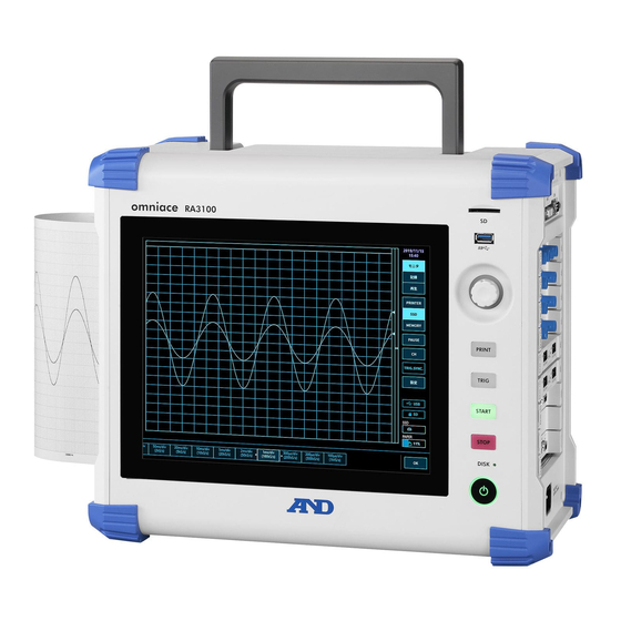
1.Name and Function of Each Block - 1.1.Name of Each Block 1. Name and Function of Each Block This product consists of the following blocks. 1.1. Name of Each Block Front view Handle (retractable) SD card slot Display Block Operation panel Power switch Corner pad Screen lock... -
Page 15: Display Block
1. Name and Function of Each Block - 1.2.Display Block 1.2. Display Block This product has a TFT color LCD display with touch panel. The LCD displays the waveform monitor and settings keys, and users can configure settings by directly touching the panel. -
Page 16: Operation Panel
1.Name and Function of Each Block - 1.3.Operation Panel 1.3. Operation Panel (1) SD card slot Used to save recorded data to an SD memory card, etc. (2) USB Used to save recorded data to USB memory, etc. in the same manner as to an SD memory card. -
Page 17: Input Module Block
1. Name and Function of Each Block - 1.4.Input Module Block 1.4. Input Module Block Input Module Block Slot 1 Slot 2 Slot 3 Up to nine modules can be installed to the input module block of the Slot 4 product. -
Page 18: Side Menu
1.Name and Function of Each Block - 1.5.Screen and Setup Menu 1.5.1. Side menu (1) Time: Displays the current time (2) MEASURE/PLAYBACK: Switches the displayed waveform MEASURE: Displays the current input waveform. PLAYBACK: Displays the playback waveform of saved data. (3) Waveform display area: Select waveform recording device to display Displays the recorded waveform for PRINTER/SSD/MEMORY. -
Page 19: Control Bar
1. Name and Function of Each Block - 1.5.Screen and Setup Menu 1.5.2. Control Bar The control bar provides a menu for the functions frequently used with the waveform monitor, such as waveform display control of sampling, etc., thumbnail display, cursor display, and pen recorder control. Tap the (7) Display switch key on the right edge of the control bar to switch the functions in the order... - Page 20 1.Name and Function of Each Block - 1.5.Screen and Setup Menu Control bar when playback Touch the PLAYBACK key on the side menu to enter the playback mode and switch the control bar to the menu for playback. (1) Sampling speed : Displays the sampling speed of the recorded data.
-
Page 21: Pre-Measurement Procedures
2.Pre-Measurement Procedures - 2.1.Before Switching On the Power 2. Pre-Measurement Procedures 2.1. Before Switching On the Power The preparations for using this product and the cautions are explained below. 2.1.1. Installation and Usage Environment Use this product on a flat, level surface. When using the printer, install it so that the recording paper is level as indicated in the figure on the right. -
Page 22: Installing Input Modules
2.Pre-Measurement Procedures - 2.1.Before Switching On the Power 2.1.2. Installing Input Modules WARNING In order to prevent electrocution and damage to the product, make sure to turn the power off and remove the power cable and signal input cable from the main unit before replacing an input module. In order to prevent electrocution or damage to the main unit caused by infiltration of foreign material, make sure to install the included empty panels to unused slots. -
Page 23: Paper Loading
2.Pre-Measurement Procedures - 2.1.Before Switching On the Power 2.1.3. Paper Loading The procedure for loading recording paper to the printer block is indicated below. Load the recording paper to this product. There are two types of recording paper: paper rolls and Z-fold paper. - Page 24 2.Pre-Measurement Procedures - 2.1.Before Switching On the Power Step 3. Load the paper following the guide of the product. NOTE Load the recording paper following the guide of the product, and press the paper holders into the guide until a click is heard. Be sure the paper roll is loaded so that the thermally sensitive side is faced toward you;...
-
Page 25: Turning The Power On/Off
2.Pre-Measurement Procedures - 2.2.Turning the Power On/Off 2.2. Turning the Power On/Off 2.2.1. Connecting the AC Power Cable Be sure to check the following points before connecting the AC power cable to this product. Make sure that the power supply matches the rating indicated on the rating plate attached to this product. -
Page 26: Confirming Normal Startup
2.Pre-Measurement Procedures - 2.2.Turning the Power On/Off Step 4. Turn the Power switch of the product on. When the power switch on the operation panel of the product is turned on, the green LED lights up and the power turns on. NOTE Standby current flows to this product when the AC power cable is connected to the power outlet. -
Page 27: Flow Of Measurement
3.Flow of Measurement- 3.1.Flow of Measurement 3. Flow of Measurement This product records and play back input signals following the procedures described below. 3.1. Flow of Measurement Perform the check Chapter Confirm that this product has been set in a safe place, and that all the before applying power accessories are properly attached. -
Page 28: Configuring Measurement
4.Configuring Measurement - 4.1.Reducing the Input Sensitivity and Connecting the Input Cable 4. Configuring Measurement 4.1. Reducing the Input Sensitivity and Connecting the Input Cable Step 1. The input signal can be displayed and checked in realtime by switching the MEASURE /PLATBACK key on the side menu to... - Page 29 4.Configuring Measurement - 4.1.Reducing the Input Sensitivity and Connecting the Input Cable Step 5. Tap the tab in the channel setup sub menu to change the displayed channel. Step 6. To change the display slot of the input module, swipe the channel setup sub menu left or right, or tap the <...
-
Page 30: Setup The Input Channel
4.Configuring Measurement - 4.2.Setup the Input Channel 4.2. Setup the Input Channel 4.2.1. Channel Setup sub menu (For RA30-101) Slot number, input module type (2) Change slot: You can change the display slot by swiping this sub menu left or right or tapping the left <... -
Page 31: Set The Input Channels
4.Configuring Measurement - 4.2.Setup the Input Channel 4.2.2. Set the Input Channels The input waveform is displayed on the monitor when a signal is connected to the input module. The overall procedure for setting the input channel is indicated below. See the following for details on each step. - Page 32 4.Configuring Measurement - 4.2.Setup the Input Channel Description of Step 3 (setting the filter) (procedure on page 30) Set the filter of the selected channel. This cuts out unnecessary frequency components and noise. As the filter differs according to the input module type, set the filter according to the characteristics of the input signal and measurement.
- Page 33 4.Configuring Measurement - 4.2.Setup the Input Channel Description of Step 5 (setting the display maximum and display minimum (waveform display scale)) (procedure on page 30) If the amplitude of the input signal is smaller than the set range, the signal change may be hard to recognize.
-
Page 34: Recording Setup
4.Configuring Measurement - 4.3.Recording Setup 4.3. Recording Setup 4.3.1. Setup the Sampling Speed An image of the waveform recorded on the selected recording device (PRINTER, SSD, or MEMORY) is displayed on the waveform monitor. The sampling speed of the image waveform recorded on the selected recording device is displayed on the left edge of the control bar. -
Page 35: Sampling Speed Of Recording Device
4.Configuring Measurement - 4.3.Recording Setup 4.3.2. Sampling Speed of Recording Device There are three types of recording device (PRINTER, SSD, and MEMORY). The sampling speed setting range and characteristics of each device are indicated below. Setting range 100 ms/div (1 kS/s) 10 min/div (10 S/min) Records the waveform to the long-term printer at low speed. -
Page 36: Relationship Between Sampling Speed And Chart Speed
4.Configuring Measurement - 4.3.Recording Setup If the input signal is too fast for the sampling period, the waveform reproducibility may drop and lead to the unexpected loss of pulses. Raising the sampling speed improves the waveform reproducibility but increases the recorded data. Sampling data Sampling period Time... -
Page 37: Trigger Setup
5.Trigger Setup - 5.1.Trigger Types 5. Trigger Setup 5.1. Trigger Types This product has two types of triggers : Memory trigger for memory recording and Start trigger for starting recording. 5.2. Memory Trigger Memory trigger is a signal for enabling memory recording, and is occurred when the trigger conditions of the channel specified in the trigger source are established. - Page 38 5.Trigger Setup - 5.2.Memory Trigger Step 3. Up to 18 trigger sources can be set. Tap the number of the trigger source to set to display the details screen. (1) Trigger menu selection: Switches between the Memory trigger, Start trigger, or Memory block menu (2) Channel: Selects the TRIGn source channel.
- Page 39 5.Trigger Setup - 5.2.Memory Trigger Change threshold with rotary knob Trigger source Channel signal Trigger point The threshold (trigger level) is displayed in red Press and hold the threshold, and change the threshold with the numeric keys When the trigger direction is set to UP, the trigger point is when the input signal exceeds the trigger level Description of trigger source...
-
Page 40: Pre-Trigger
5.Trigger Setup - 5.3.Pre-Trigger Description of trigger source (5) Filter Settings on page 38 Trigger filter The trigger filter function ensures that a trigger is detected when the trigger conditions are met for a specified period of time, in order to prevent erroneous trigger detection due to noise or chattering in the signal near the trigger level. -
Page 41: Start Trigger
5.Trigger Setup - 5.4.Start Trigger 5.4. Start Trigger The start trigger function starts recording when the trigger conditions are established for the channel specified in the trigger source. Press the START key on the operation panel to put the product in the standby state. -
Page 42: Measuring Input Signals
6 - Measuring Input Signals 6. Measuring Input Signals 6.1. State Transition of Main Unit Operation This product is divided into three states according to the operation state: monitor, record, and playback. PRINT key can also be pressed in the monitor display state to perform real-time waveform printing (pen recording) via the internal printer. -
Page 43: Monitor Display And Pen Recording
6.Measuring Input Signals - 6.2.Monitor Display and Pen Recording 6.2. Monitor Display and Pen Recording 6.2.1. Monitor Display Function Tap the recording device selection in the side menu to display the image waveform recorded on the selected device on the waveform monitor. Printer recording SSD recording Memory recording... - Page 44 6.Measuring Input Signals - 6.2.Monitor Display and Pen Recording Pausing Tap the PAUSE key on the waveform monitor to stop the monitor. In this state, you can pinch in (reduce) or pinch out (expand) the waveform on the waveform monitor. You can also use one finger to drag the screen up, down, left, or right to move the display area.
- Page 45 6.Measuring Input Signals - 6.2.Monitor Display and Pen Recording X-Y Waveform and FFT Analysis When is selected as the recording device and NORMAL is selected as the data format, FFT analysis and the X-Y waveform display for the control bar waveform format are enabled. X-Y waveform conditions Recording device: Sampling speed:...
-
Page 46: Pen Recording
6.Measuring Input Signals - 6.2.Monitor Display and Pen Recording 6.2.2. Pen Recording Pen recording enables direct waveform printing to the recording paper without saving the measurement data. This enables single-touch simple and certain waveform recording like a conventional pen recorder. Pen Recording Press the PRINT... -
Page 47: Setup And Printing Annotations
6.Measuring Input Signals - 6.2.Monitor Display and Pen Recording 6.2.3. Setup and Printing Annotations This product has a function for printing header, annotation, and footer text before, during, and after waveform recording with the printer. Tap the Annotation printing key during waveform recording to print annotations overlaid on the waveform. -
Page 48: Starting And Ending Recording
6.Measuring Input Signals - 6.3.Starting and Ending Recording 6.3. Starting and Ending Recording This product has three recording devices: printer, memory, or SSD. When recording is enabled for a device, the data recorded to each device is recorded to the SSD while it is recorded to the device. For the printer, the waveform data (P-P values) printed to the recording paper are also recorded to the SSD. - Page 49 6.Measuring Input Signals - 6.3.Starting and Ending Recording (1) Mode: Selects the optimal mode from the nine recording modes. (2) Data name: Specifies the name of the recorded data. When [Automatic numbering] is enabled, numbers are automatically appended to the name. (3) Recording time: Ends recording after recording for the specified time after recording starts.
-
Page 50: Starting And Ending Recording
6.Measuring Input Signals - 6.3.Starting and Ending Recording 6.3.2. Starting and Ending Recording Starting Recording Press the START key on the operation panel to start device recording and enclose the screen with a red frame. Red frame Ending Recording Recording ends when the recording time set in Recording time elapses or when the STOP key... -
Page 51: Pausing Recording And Scrolling Back
6.Measuring Input Signals - 6.3.Starting and Ending Recording When the memory waveform is displayed on the monitor, you can display the Trigger tab from on the side menu to display [Memory block] for checking the recorded memory data. Tap and change the display block number with the rotary knob. -
Page 52: Playback Recorded Data
7.Playback Recorded Data - 7.1.Select Recorded Data 7. Playback Recorded Data To playback recorded data, tap PLAYBACK MEASURE/PLAYBACK on the side menu to switch the monitor to the playback screen. The monitor automatically switches to the playback screen when measurement ends. PLAYBACK key Select recording device Waveform format... -
Page 53: Playback Recorded Data
7.Playback Recorded Data - 7.2.Playback Recorded Data 7.2. Playback Recorded Data By displaying a waveform in the playback monitor and selecting a device in the side menu, the waveform for each device when recording is displayed. Select recording device Move display area Y axis Enlarge/reduce Time axis... -
Page 54: Cursors
7.Playback Recorded Data - 7.2.Playback Recorded Data 7.2.2. Cursors When CURSOR is selected for the Control bar switching on the right edge of the control bar, the A and B time axis cursors are displayed. Cursor A Cursor B Turn the rotary knob to move the cursors. -
Page 55: Printing Out
7.Playback Recorded Data - 7.2.Playback Recorded Data (5) Channel selection Selects the channel to display in the cursor position information. Tap the channel selection key to display the channel selection screen indicated below, where you can select the channel to display in the cursor position information. -
Page 56: Record Management
7.Playback Recorded Data - 7.3.Record Management 7.3. Record Management The method for managing data recorded with this product is explained below. Record management in the main unit settings in SETUP on the side menu to display the [Record management] screen. A list of the recorded data on the internal SSD of the product is displayed on the left side of the [Record management] screen. -
Page 57: Export - Backing Up Recorded Data
7.Playback Recorded Data - 7.3.Record Management 7.3.1. Export - Backing Up Recorded Data Connect the external storage media (such as SD memory card or USB stick) to the main unit and confirm that the SD/USB indicator on the side menu activates. Tap the Import/Export key on the bottom right of the... -
Page 58: Restoring Recording Settings
7.Playback Recorded Data - 7.3.Record Management 7.3.3. Restoring Recording Settings The recording settings of this product are saved together with the recorded data. Select the data for the recording settings to restore/set again on the [Record management] screen, and tap the Restore recording settings key to set the recording settings to the main unit. - Page 59 7.Playback Recorded Data - 7.3.Record Management The image data saved to the main unit is read from [Main unit settings] - [Record management] - [Image management] and can be exported, printed, or deleted with the Export key, Print key, Delete key.
-
Page 60: Specifications
8.Specifications - 8.1.General Specifications 8. Specifications 8.1. General Specifications 8.1.1. Main Unit Basic Specifications Item Specifications Input block Number of module slots 9 slots Analog input Maximum 36 channels Logic input Maximum 144 channels Recording device Internal SSD 256 GB Internal memory 4 GB Internal printer... -
Page 61: General Specifications
8.Specifications - 8.1.General Specifications 8.1.2. General Specifications Item Specifications Power Rated power voltage AC 100 to 240 V AC 90 to 264 V Allowed range of variation in power voltage 50/60 Hz Rated power frequency 47 to 63 Hz Allowed range of variation in power frequency Between power and case 1500 V AC for 1 minute... - Page 62 8.Specifications - 8.1.General Specifications The Pollution Degree indicates the level of pollution that can exist in the ambient environment. Pollution degree 1: No pollution or only dry, non-conductive pollution occurs. The pollution has no influence. Pollution degree 2: Only non-conductive pollution occurs except that occasionally a temporary conductivity caused by condensation is to be expected.
-
Page 63: Functional Specifications
8.Specifications -8.2.Functional Specifications 8.2. Functional Specifications 8.2.1. Measurement Function Item Specifications Recording mode The recording modes are indicated below. (1) Standard (2) Start time (3) Start trigger (4) Interval (N times) (5) Start time + Start trigger (6) Start trigger + Interval (N times) (7) Start time + Interval (N times) (8) Start time + Start trigger + Interval (N times) (9) Window recording... -
Page 64: Ssd Recording
8.Specifications -8.2.Functional Specifications 8.2.2. SSD Recording Item Specifications Function Records input data directly to the internal SSD. Recording device Internal SSD 256 GB Number of Analog 36 ch (max) channels Logic 144 ch (max) Data format NORMAL data Samples and records data at the set sampling speed. Records the two peak values (max/min) of the data within P-P data the set sampling speed period sampled at 20 MS/s. -
Page 65: Memory Recording
8.Specifications -8.2.Functional Specifications 8.2.3. Memory Recording Item Specifications Function Records to the internal memory with high-speed sampling. Recording device Internal memory 2 GW Record blocks Divided into 1 to 200 user-defined blocks (number of memory divisions) Points The number of data items per channel that can be recorded to a recording block 2 kW to 2 GW (selected in step 1-2-5) Channels x points x blocks ≤... -
Page 66: Trigger Function
8.Specifications -8.2.Functional Specifications 8.2.5. Trigger Function [Basic trigger function] Item Specifications Trigger function Start trigger Start trigger for recording operation Memory trigger Trigger for memory recording Trigger type Analog input signal Level trigger Trigger when an analog signal transects (rises above/falls Window trigger below) the set threshold INTO WIN: Trigger when the analog signal enters the... -
Page 67: Monitor Function
8.Specifications -8.2.Functional Specifications 8.2.6. Monitor Function Item Specifications Display screen MEASURE Displays the state waveform of the input signal PLAYBACK Playback the memory, SSD, or printer recorded data Waveform type Y-T waveform, X-Y waveform, FFT waveform Enables waveform display for an arbitrary analog signal and logic signal Y-T waveform Enables 48 channel/sheet signal display X-Y waveform... -
Page 68: Fft Analysis
8.Specifications -8.2.Functional Specifications Item Specifications Pen up Pauses measurement The pen up operation can be performed for one waveform at a time or all waveforms at once Resumes measurement The pen down operation can be performed for one waveform Pen down at a time or all waveforms at once Clear Clears the displayed... -
Page 69: Setup / Record Management
8.Specifications -8.2.Functional Specifications 8.2.9. Setup / Record Management Item Specifications Recording Setup Recording Mode Nine type recording mode display and selection. Data name Recording name, automatic numbering. Recording time Recording time setting for one time, maximum time settable from remaining SSD capacity. Start time Set the recording start time Interval time... - Page 70 8.Specifications -8.2.Functional Specifications Item Specifications Record Management List of recorded Displays a list of the data recorded to this product. data Choice Selects recorded data in the list. Multiple data can be selected. Select all Selects all the recorded data in the list. Release all Deselects all the data in the list.
-
Page 71: Interface Specifications
8.Specifications -8.2.Functional Specifications 8.2.10. Interface Specifications Item Specifications Supported standard IEEE802.3 (1000BASE-T, 100BASE-TX, 10BASE-T) Connector RJ-45 Number of ports Supported standard USB3.0 Connector Type-A Number of ports Supported standard SD standard (SD/SDHC/SDXC supported) Connector Slot for SD memory cards Number of ports Supported standard EIA-574 Connector... -
Page 72: Other Settings (Maintenance / Operation History / Version Management)
8.Specifications -8.2.Functional Specifications 8.2.12. Other Settings (Maintenance / Operation History / Version Management) Item Specifications SSD check SSD life remaining, health check, and loading test Fan check Displays the state of the internal cooling fan LCD check LCD screen check and pixel defect check Brightness check LCD back light brightness control check Printer... -
Page 73: Exterior
8.Specifications -8.3.Exterior 8.3. Exterior 8.3.1. Main Unit Exterior 1WMPD4004445... - Page 74 8.Specifications -8.3.Exterior MEMO 1WMPD4004445...
- Page 75 Omniace RA3100 Simple Instruction Manual 1WMPD4004445 1st Edition...
- Page 76 3-23-14 Higashi-Ikebukuro, Toshima-ku, Tokyo 170-0013, JAPAN Telephone: [81] (3) 5391-6132 Fax: [81] (3) 5391-1566 A&D ENGINEERING, INC. 1756 Automation Parkway, San Jose, California 95131, U.S.A. Telephone: [1] (408) 263-5333 Fax: [1] (408)263-0119 A&D INSTRUMENTS LIMITED Unit 24/26 Blacklands Way, Abingdon Business Park, Abingdon, Oxfordshire OX14 1DY United Kingdom Telephone: [44] (1235) 550420 Fax: [44] (1235) 550485 A&D AUSTRALASIA PTY LTD...
Need help?
Do you have a question about the Omniace RA3100 and is the answer not in the manual?
Questions and answers