Table of Contents
Advertisement
Quick Links
Advertisement
Table of Contents

Related Manuals for A&D AD-4532B


Summary of Contents for A&D AD-4532B
- Page 1 AD-4532B Digital Indicator INSTRUCTION MANUAL 1WMPD4001683...
- Page 2 WARNING DEFINITIONS The warnings described in this manual have the following meanings: A potentially hazardous situation which, if not avoided, could result in death or serious injury. A potentially hazardous situation which, if not avoided, may result in minor or moderate injury or damage to the instrument . This symbol indicates caution against electrical shock.
-
Page 3: Table Of Contents
CONTENTS 1. INTRODUCTION ..........................3 1-1 Features ............................. 3 2. PRECAUTIONS ..........................4 2-1 Unpacking............................4 2-2 Precautions Before Use........................4 2-3 Precautions During Use........................5 3. SPECIFICATIONS...........................6 4. FRONT PANEL ..........................8 5. REAR PANEL ..........................10 5-1 Description of Each Terminal......................10 6. - Page 4 13-2 Output Terminal ..........................54 14. CHECK MODE..........................55 14-1 Check Mode Procedure........................55 15. OPTIONS ............................60 15-1 AD-4532B-01 BCD Parallel Output....................60 15-2 AD-4532B-04 RS-232C Serial Interface..................62 15-3 AD-4532B-07 Analog Voltage/Current Output (DAV/DAI) .............. 65 15-4 AD-4532B-08 Ethernet Interface ....................68...
-
Page 5: Introduction
1. INTRODUCTION Thank you for purchasing the AD-4532B, Digital Indicator. This manual describes how the AD-4532B works and how to get the most out of it in terms of performance. Please read this manual completely before using the AD-4532B. 1-1 Features The AD-4532B has the following features. -
Page 6: Precautions
2. PRECAUTIONS The AD-4532B is a precision instrument. To get the most from your AD-4532B, observe the following precautions. 2-1 Unpacking Unpack the AD-4532B carefully and confirm that everything is contained. Keep the packing material if you want to transport the indicator again in the future. -
Page 7: Precautions During Use
2-3 Precautions During Use The AD-4532B is a precision instrument that measures the microvolt output from sensors. Prevent noise sources such as power lines, radios, electric welders or motors from affecting the instrument. Do not try to modify the AD-4532B. -
Page 8: Specifications
3. SPECIFICATIONS Number of measurement points Sensor type Strain gauge sensors (Output resistance: 10kΩ or less) Sensor power supply (Excitation voltage: To be switched by the function setting.) (1) 5 VDC 350Ω sensor: Up to four sensors can be connected. (1) 2.5 VDC 120Ω... - Page 9 AD-4532B-04: RS-232C serial interface AD-4532B-07: DAV/DAI (analog voltage output/analog current output) AD-4532B-08: Ethernet interface Note: Only one of the options can be installed in the AD-4532B at a time. General specifications Power requirement: 85 VAC to 250 VAC, 50/60 Hz, Approx. 20 VA Operating temperature: -5°C to +40°C...
-
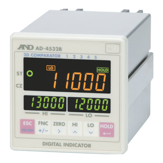
Page 10: Front Panel
4. FRONT PANEL Standby indicator 5-level comparator indicators Status indicators Main display Stabilization indicator Sub-display (right) Zero indicator Keys Sub-display (left) Main display Displays a measured value or set value. To set the decimal point position, use function mode f-00. Sub-displays Displays an upper limit value (left side) or lower limit value (right side), or displays the set value. - Page 11 Keys When this key is pressed for more than three seconds, the display will turn on or off. Even during the display-off state, the power is supplied to the indicator and the ON/OFF standby indicator turns on. Pressing this key in each mode cancels the current state and returns to the previous state.
-
Page 12: Rear Panel
5. REAR PANEL This chapter explains the terminals on the rear panel and how to connect sensors. For the position of each terminal, see the illustration below. (19) Terminal numbers that are printed on the top of the indicator casing Confirm the terminal numbers when making connections When making connections, confirm the terminal numbers printed on the side of the terminal block and on the top of the indicator casing. - Page 13 5-1-2 Comparator output terminals (31) (32) (33) (34) (31) HI output terminal Outputs HI when the measured value exceeds the upper limit value. (32) OK output terminal Outputs OK when the measured value is as shown below. Lower limit value ≤ measured value ≤ upper limit value (33) LO output terminal Outputs LO when the measured value does not reach the lower limit value.
- Page 14 5-1-4 Modbus RTU terminals (1) - (4) (1) FG terminal Frame ground terminal for Modbus. Connects the Modbus cable shield here. (2) (3) RS-485 terminals A and B terminals for the RS-485, that the Modbus RTU uses. (4) SG terminal Signal ground terminal for the RS-485.
- Page 15 5-1-6 DAV output terminals (D/A voltage output) (10) - (12) (10) FG terminal Frame ground terminal for the DAV output. Connects the DAV output cable shield here. (11) DAV output terminal DAV output is –10 V to +10 V. Scaling is available by the function setting. (12) DAV output ground terminal 5-1-7 Analog amplifier output terminals (13) - (15) (13) FG terminal...
-
Page 16: Components And Functions
6. COMPONENTS AND FUNCTIONS The following flowchart shows how the functions of the AD-4532B are executed. 6-1 Flowchart Input from sensor Input filter Analog amplifier output A/D conversion 2000 times/s Moving average filter Digital filter External input Measured value Hold... -
Page 17: Description Of Functions
Select a high frequency when high-speed measurements are required and a low frequency when stable measurements are required. 6-2-5 External input The AD-4532B has nine external inputs, ZERO, HOLD, LATCH, COMP ON, COMP 1 to COMP 5 (5-level comparator). Maintain the inputs for more than 10 ms. 6-2-6 Hold As digital filtered data is used, high-speed hold is enabled. - Page 18 6-2-10 Modbus RTU The AD-4532B has Modbus RTU protocol. The values that the AD-4532B indicates and the AD-4532B status can be read and the set values of the AD-4532B can be written, using Modbus RTU. This is used, for example, to read measured values or change the settings when connecting the...
-
Page 19: Calibration
7. CALIBRATION The AD-4532B measures voltage signals from sensors and displays the values. Calibration is performed on the AD-4532B so that it performs correctly. 7-1 Description of Calibration Calibration has the following setting items and operations. Minimum division setting Selects the minimum division. -
Page 20: Calibration Modes
7-2 Calibration Modes There are three calibration modes. Digital span mode (d-5p) The sensor’s rated output voltage is keyed in. Calibration is performed without using an actual load. Calibration mode (Cal) Zero and span calibration are carried out using an actual load. Full calibration mode (fCal) Zero and span calibration are carried out using an actual load after minimum division and rated capacity have been set. -
Page 21: Digital Span Mode
7-3 Digital Span Mode The sensor’s rated output voltage is keyed in. Calibration is performed without using an actual load. 7-3-1 Setting the minimum division displayed, press the ↵ key to go to the digital span 1. With d-5p d-5p mode. - Page 22 7-3-3 Zero calibration 4. With nothing placed on the load cell, press the 1↵ key. Cal0 1↵ Performs zero calibration and goes to step 5. d-5p Cancels the operation and returns to the d-5p display. Digital span calibration 7-3-4 Digital span calibration 32000 5.
-
Page 23: Calibration Mode
7-4 Calibration Mode Zero and span calibration are carried out using an actual load. 7-4-1 Zero calibration 1. With Cal displayed, press the ↵ key to enter the calibration mode. 2. With nothing placed on the load cell, press the 1↵ key. 1↵... -
Page 24: Full Calibration Mode
7-5 Full Calibration Mode Zero and span calibration are carried out using an actual load after minimum division and rated capacity have been set. 7-5-1 Setting the minimum division fCal ↵ 1. With fCal displayed, press the key to enter the full calibration mode. - Page 25 7-5-3 Zero calibration Cal0 4. With nothing placed on the load cell, press the 1↵ key. 1↵ Performs zero calibration and goes to step 5. fCal Cancels the operation and returns to the fCal display. ------ fCal Cal0 Span calibration 7-5-4 Span calibration 5.
-
Page 26: Function Mode
8. FUNCTION MODE By selecting the function mode, various functions and data can be set. The set values saved, even if the power is off, are maintained in non-volatile memory. 8-1 Setting a Function 8-1-1 Starting the function mode 1. In the measurement mode, press the FNC key for three seconds or more to enter the function selection mode. -
Page 27: Description Of The Function Items
8-2 Description of the Function Items Item and Parameter Description e.g.: 123456 No decimal point e.g.: 12345. 6 1 decimal place Decimal f-00 e.g.: 1234. 5 6 2 decimal places point Decimal point position e.g.: 123. 4 56 3 decimal places e.g.: 12. - Page 28 Item and Parameter Description 0000 0 0 0 0 0: Permit 1: Inhibit To permit or inhibit zero adjustment by the ZERO key. To permit or inhibit the hold function by the HOLD key. f-12 Keys Inhibit by key To permit or inhibit monitoring the upper/lower limit values. To permit or inhibit changing the upper/lower limit values.
- Page 29 Item and Parameter Description COMP ON by control input is not required. Not used f-18 Always COMP ON COMP ON Select this when the 2D comparator mode is Used used. Upward 2-level judgment f-19 Upper/lower limit judgment Hysteresis mode Comparator Downward 2-level judgment (continued) f-20...
- Page 30 Item and Parameter Description f-31 Reserved internally f-32 Positive BCD output logic Negative 1 time/s 10 times/s f-33 100 times/s BCD output rate 1000 times/s 2000 times/s In sync with the display f-34 -20000 Sets the measured value that corresponds to DAV/DAI Measured value at output value of 0V/4mA.
-
Page 31: Hold Function
Holding time after releasing hold The AD-4532B has a function to hold the value for a certain period of time after the hold function is stopped. To set the holding time, use function mode f-15. During the holding time, the HOLD indicator blinks. -
Page 32: Hold Modes
9-2 Hold Modes 9-2-1 Sample hold mode Holds the display and output when receiving the hold input. Sensor input Displayed value HOLD key Front panel During the holding operation, HOLD turns on. External hold input Rear panel 9-2-2 Peak hold mode Holds the peak value when receiving the hold input. - Page 33 9-2-3 Bottom hold mode Holds the bottom value when receiving the hold input. Sensor input Displayed value HOLD key Front panel External hold input Rear panel During the holding operation, HOLD turn on. PEAK 9-2-4 Bipolar peak hold mode Holds the absolute peak value when receiving the hold input. Sensor input Displayed value HOLD...
-
Page 34: Comparator Function
10. COMPARATOR FUNCTION The AD-4532B has two comparator modes; simple comparator and 2D (Two dimensional) comparator. A comparator mode can be selected in function mode f-16. f-17 to f-21 are also comparator-related function modes. The comparator function compares the measured value against the set value and outputs the comparison results (HI, OK or LO) from the rear panel comparator output terminals. - Page 35 10-1-2 Setting the upper and lower limit values 1. In the measurement mode, press the HI key or LO key to check the 4532 upper limit value or lower limit value. 1000 2. In the main display, Hi or lo appears.
- Page 36 10-1-3 Example of the simple comparator mode Example: f-16 2 (Continuous comparison, excluding the zero band) Upper limit Lower limit Zero band COMP ON HI output OK output LO output COMP ON input and output HI, OK or LO output is available only when the COMP ON input terminal is ON (when the COMP ON input terminal is connected to the IN COM terminal).
-
Page 37: Comparator Mode
10-2 2D Comparator Mode The 2D (Two dimensional) comparator mode performs a two dimensional comparison by switching the 5-level comparator with the upper and lower limit values that are preset for each level. 10-2-1 Switching the comparator Two switching methods are available. By COMP 1 to COMP 5 inputs (f-16 4 or 5) Switching is performed by the change in position. -
Page 38: Comparator Mode (By Comp 1 To 5 Inputs)
10-3 2D Comparator Mode (By COMP 1 to 5 inputs) 10-3-1 Setting the upper and lower limit values for each level 4532 1. In the measurement mode, press the HI key or LO key to check the upper limit value or lower limit value. 1000 2. - Page 39 10-3-2 Example of the 2D comparator mode (By COMP 1 to 5 inputs) Example: f-16 5 (5-level continuous comparison) When the judgment result is OK: Hi 5 lo 5 Hi 3 lo 3 Hi 4 Hi 2 lo 4 lo 2 Hi 1 lo 1 COMP ON...
- Page 40 When the judgment result is NG: Hi 5 Hi 3 lo 5 lo 3 Hi 4 Hi 2 lo 4 lo 2 Hi 1 lo 1 COMP ON COMP 1 COMP 2 COMP 3 COMP 4 COMP 5 HI output OK output LO output...
-
Page 41: Comparator Mode (By Time Control)
10-4 2D Comparator Mode (By time control) 10-4-1 Setting the upper and lower limit values for each level 1. In the measurement mode, press the HI key or LO key to check the 4532 upper limit value or lower limit value. 1000 2. - Page 42 10-4-2 Example of the 2D comparator mode (By time control) Example: f-16 7 (5-level continuous comparison) with the starting and ending time for each level that are set as below. t1 5t t1 end Level 1 Unit: ms t2 5t t2 end Level 2 Level 3...
- Page 43 When the judgment result is NG: Hi 5 Hi 3 lo 5 lo 3 Hi 4 Hi 2 lo 4 lo 2 Hi 1 lo 1 COMP ON 1000 1100 1200 1300 1400 HI output OK output LO output...
-
Page 44: Comparator Mode (Additional Explanation)
10-5 2D Comparator Mode (Additional Explanation) While the conventional comparison method detects and judges the maximum or minimum value only during measurement, the 2D comparator mode uses contact inputs from the rear panel terminals or elapsed time to make a comparison at various levels. This type of comparison is useful for an operation such that the pressure increases rapidly at the pressurization starting time and changes in pressure occur during the pressurization process. -
Page 45: Comparator Hysteresis Function
10-6 Comparator Hysteresis Function A hysteresis width and time is provided for the output relay on/off timing to prevent the output terminals from chattering. When the measured value exceeds the set value, the relay is turned on. If the measured value falls below the set value and it is further reduced by the hysteresis width, or if the hysteresis time has elapsed, the relay is turned off. - Page 46 10-6-2 Upper/lower limit judgment (f-19 1) Relation between OK and HI When the measured value exceeds the set upper limit value, HI is output. Even if the measured value falls below the upper limit value after that, OK is not output immediately. OK will be output when the measured value is reduced by the hysteresis width, or when the hysteresis time has elapsed.
- Page 47 10-6-3 Downward 2-level judgment (f-19 2) Relation between OK and HI Even if the measured value exceeds the set upper limit value, HI is not output immediately. HI will be output when the measured value is increased by the hysteresis width, or when the hysteresis time has elapsed.
-
Page 48: Analog Output
11. ANALOG OUTPUT The AD-4532B has two types of analog output; the analog amplifier output (AAO) that amplifies the sensor’s analog signals and outputs the amplified signal, and the digital to analog voltage output (DAV) that processes the measured values from the sensors according to the values set in function mode, and outputs the processed signal as a voltage after D/A conversion. -
Page 49: Digital To Analog Voltage Output (Dav)
11-2 Digital to Analog Voltage Output (DAV) Processes the measured values from the sensors according to the values set in function modes f-22 to f-24, and outputs the processed signal as a voltage after D/A conversion. The output voltage range is from –10 V to +10 V. Scaling is available in function modes f-22 and f-23. 11-2-1 Specifications Rated output range –10 V to +10 V (Non-inductive load of 5 kΩ... - Page 50 dav 0v 3 . When dav 0v is displayed, adjusting 0V is enabled. In the right side of the sub-display, the internal correction factor for valUe 32768 the DAV output appears. Use the following keys to adjust the output voltage while looking at dav 0v the digital multimeter.
-
Page 51: Modbus Rtu Interface
12. Modbus RTU INTERFACE The Modbus RTU interface reads the measured values or status from the AD-4532B, or writes the settings to the AD-4532B. Using the Modbus RTU interface, a personal computer, PLC or programmable display can be connected to the AD-4532B. - Page 52 12-1-2 Data address Data type Address Data Data format Hold Release hold Coil Zero 1 bit 0XXXX Clear zero Save settings in EEPROM Hold Stable Zero band Rated capacity overflow AD conversion overflow HI output LO output OK output Level 1 HI output Level 1 LO output Level 1 OK output Input status...
- Page 53 Data type Address Data Data format 1, 2 Upper limit 3, 4 Lower limit 5, 6 Level 1 upper limit 7, 8 Level 1 lower limit 9, 10 Level 2 upper limit 11, 12 Level 2 lower limit 13, 14 Level 3 upper limit 15, 16 Level 3 lower limit...
-
Page 54: Connection Procedure
12-2 Connection Procedure 12-2-1 When making a connection between a master device and one indicator A device such as Programmable display AD-4532B Termination resistor Master Slave Use a shielded twisted pair cable to make a connection. Connect termination resistors without fail. (100Ω to 120Ω, 1/2 W to 2 W) The positions of A and B may be reversed for some master devices. -
Page 55: Input And Output
13. INPUT AND OUTPUT The AD-4532B has nine input terminals and three output terminals. 13-1 Input Terminal Equivalent circuit diagram +5 V Toggle switch Mechanical relay contact 19 to 26 Semiconductor contact Approx.4 mA (Transistor open collector) Mechanical タ contact... -
Page 56: Output Terminal
13-2 Output Terminal Equivalent circuit diagram Non-polar MOS FET relay 31 to 33 Load AC power supply Varistor AD-4532B interior Contact rating 31 to 33 250 VAC 0.1 A Load 30 VDC 0.5 A DC power supply Spark killer AD-4532B interior... -
Page 57: Check Mode
14. CHECK MODE The AD-4532B has check modes to check the performance of input and output terminals as follows. Display check mode, analog output check mode, I/O check mode and key check mode. 14-1 Check Mode Procedure 14-1-1 Entering a check mode 1. - Page 58 6. Press the 1↵ key to check the excitation voltage supplied to the volt sensor from the AD-4532B. In the example display shown to the right, the excitation voltage is 5 V Press the 1↵ key to go to the DAV voltage check mode dav.
- Page 59 14-1-7 Span calibration mV/V value check mode 10. The span calibration mV/V value check mode displays the mV/V 5pan value at span calibration. Press the 1↵ key to check the span calibration mV /V value. In the example display shown to the right, the value at span calibration is 2.18372 mV/V 2.
- Page 60 14-1-9 Key check mode 13. The key check mode checks the front panel keys. 1> Moves to the initialization mode without performing the current check mode 1↵ Enters the key check mode and goes to step 14. Returns to the CHeCk display. 14.
- Page 61 14-1-10 Initialization 15. Initialization restores the various settings to the factory setting init values. 1> Moves to the display check mode without performing the initialization. init f 1↵ Enters the initialization mode and displays init f the main display. CHeCk init Returns to the CHeCk display.
-
Page 62: Options
The BCD parallel output is an interface to convert measured values into a BCD format and output. Using this interface, the AD-4532B can be connected to a device such as a personal computer or a PLC to perform controlling, collection or recoding. - Page 63 15-1-2 Equivalent circuit diagram A1 to A16, A18, B1 to B16 pin output terminals A19, B19 pin common terminals B18 pin HOLD input terminal AD-4532B interior 15-1-3 Connector pin assignment Pin No. Direction BCD code Pin No. Direction BCD code...
-
Page 64: Ad-4532B-04 Rs-232C Serial Interface
15-2 AD-4532B-04 RS-232C Serial Interface The RS-232C serial interface can be connected to a device such as a personal computer, PLC or a programmable display, to output the values displayed by the AD-4532B and perform controlling, collection or recoding. 15-2-1 Specifications... - Page 65 15-2-4 Command format When a command is processed, the indicator transmits the received command or the data. If a command can not be processed, for example, when the indicator is in operation, the indicator transmits “I”. Communication errors may occur due to external noise. When the indicator receives an undefined command, it transmits “?”.
- Page 66 Command to send the upper/lower limit values Outputs the set upper and lower limit values including the values of the 2D comparator mode. Command: S, Sx (Where x is the comparator level of the 2D comparator mode. For example, S1 means the setting value for the level 1.) Command example: S CR LF S 1 CR LF...
-
Page 67: Ad-4532B-07 Analog Voltage/Current Output (Dav/Dai)
The DAV/DAI analog voltage/current output is an interface to output the values displayed by the AD-4532B as an analog voltage or analog current. The analog output range for voltage is from –10 V to +10 V and for current, from 4 mA to 20 mA. - Page 68 4532 Zero and span adjustment of the AD-4532B DAV/DAI are not performed externally but internally in a digital manner. Voltage is used for adjustment. 1000 The adjustment points are 0 V, +10 V and -10 V.
- Page 69 15-3-3 DAV/DAI voltage/current check This mode allows the user to check the DAV/DAI value. To use this mode, first enter the check mode. Voltage is used for checking. To check the current value (DAI), the displayed value of 0 corresponds to 4 mA and the value of 10 corresponds to 20 mA.
-
Page 70: Ad-4532B-08 Ethernet Interface
15-4 AD-4532B-08 Ethernet Interface The Ethernet interface allows communication between the AD-4532B and a personal computer. The Windows Communication Tools for Ethernet, WinCT-Plus is provided with this option. The data format and commands are the same as those of the AD-4532-04 RS-232C serial interface.
Need help?
Do you have a question about the AD-4532B and is the answer not in the manual?
Questions and answers