Table of Contents
Advertisement
Quick Links
Advertisement
Table of Contents

Related Manuals for A&D AD-4531B


Summary of Contents for A&D AD-4531B
- Page 1 1WMPD4002618B...
- Page 2 WARNING DEFINITIONS The warnings described in this manual have the following meanings: A potentially hazardous situation which, if not avoided, could result in death or serious injury. A potentially hazardous situation which, if not avoided, may result in minor or moderate injury or damage to the instrument . This symbol indicates caution against electrical shock.
-
Page 3: Table Of Contents
CONTENTS 1. INTRODUCTION .....................5 1.1. Features ..........................5 2. BEFORE USE ......................6 2.1. Precautions before use ......................6 2.2. Precautions during use ......................6 3. SPECIFICATIONS ....................8 3.1. General specifications ......................8 3.2. Functions ..........................9 3.3. Options ..........................10 4. - Page 4 10.2. Hold indicator ........................34 10.3. Priority of hold input ......................34 10.4. Values falling out of range during the hold function ............35 10.5. Hold modes ........................35 11. LATCH ........................37 12. COMPARATOR FUNCTION .................. 38 12.1. Description of the comparator mode ................38 12.2.
-
Page 5: Introduction
1. INTRODUCTION Thank you for purchasing the AD-4531B Digital Indicator. This manual describes how the AD-4531B works and how to get the most out of it in terms of performance. Please read this manual completely before using the AD-4531B. 1.1. Features The AD-4531B has the following features. -
Page 6: Before Use
When connecting long cables to the sensors, keep the cables away from power cables and other sources of electrical noise. Do not connect the AD-4531B to the power supply before installation is completed. The AD-4531B has no switch to disconnect the power supply. - Page 7 Disconnect from the power supply before removing the cover. When removing the cover, make sure that the power is disconnected. Do not touch the instrument immediately after it is disconnected from the power supply. To avoid electrical shock, do not touch the internal part of the instrument within ten seconds after disconnecting from the power supply.
-
Page 8: Specifications
3. SPECIFICATIONS 3.1. General specifications Number of measurement points Sensor type Strain gauge sensors (Output resistance: 10kΩ or less) Voltage requirement 100 VAC to 240 VAC (50/60 Hz) Power requirement Approx. 10 VA Sensor power supply 5 VDC±5%, 50 mA 120 Ω... -
Page 9: Functions
3.2. Functions ■ Digital zero (Zero adjustment) Sets the measured value to zero using the ZERO key, external input or the command signal. The zero value is saved in non-volatile memory (EEPROM). Available setting range The available setting range is 1 to 100% of the rated capacity. ■... -
Page 10: Options
Analog output AD-4530-237: Relay output, RS-485, Analog output AD-4530-247: Relay output, RS-232C, Analog output Note: Only one option can be installed in the AD-4531B at a time. 3.3.2. Option specifications ■ Relay output HI, OK, LO AD4530-200 250 VAC or 30 VDC 3A (Total current 5A) - Page 11 3.3.3. Installing an option 1. Remove the two screws that secure the guide rail, and then remove the guide rail. 2. Remove the two screws that secure the case. 3. Pull the case out from the front panel (holding it as shown). 4.
-
Page 12: Front Panel
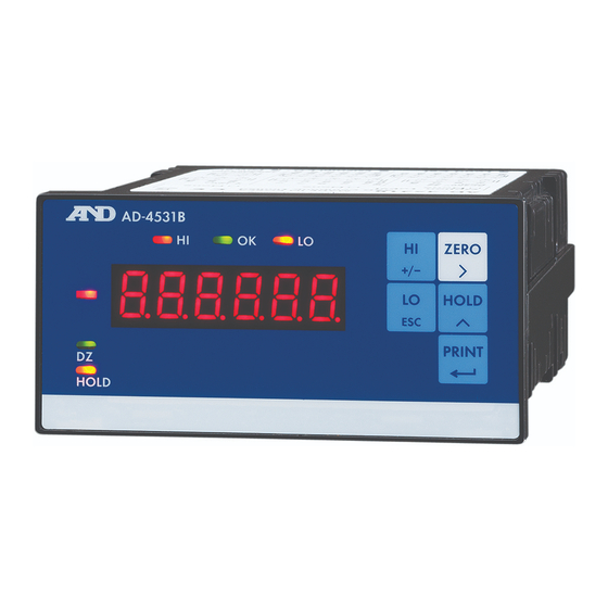
4. FRONT PANEL Display Keys 4.1. Display Displays a measured or set value. To set the decimal point position, use the function mode (Cf-01). The display is composed of six seven-segment LEDs plus a minus sign. 4.2. Status indicators Name Description Turns on when the measured value is greater than the upper limit (HI). -
Page 13: Keys
4.3. Keys Operation Function Press to proceed to the upper limit value setting mode. When inputting a numerical value, press to change the polarity. Press to proceed to the lower limit value setting mode. When inputting a numerical value, press to cancel the setting. Press to turn the digital zero function on. -
Page 14: Rear Panel
5. REAR PANEL RS-232C/RS-485 Analog output Relay output 5 4 3 2 1 1 2 3 4 5 6 7 1 2 3 4 5 6 Load cell Control input/output Confirm the terminal numbers when making connections. When making connections, confirm the terminal numbers printed on the top of the indicator case. - Page 15 (6) SEN+ Positive sensing input terminal for the sensors When performing the 4-wire connection, connect terminals 7 and 6 (EXC+ and SEN+). (7) EXC+ Positive excitation terminal for the sensors 5.1.3 Control input/output connector (1) EXT IN 1 Control input terminal 1 (2) EXT IN 2 Control input terminal 2 (3) IN COM...
-
Page 16: Equivalent Circuit Diagram Of The Control Input Section
Machine contact (Transistor open (Switch) collector) AD-4531B inner side Keep each ON and OFF time for 100 ms or more TTL open collector output * The circuit of (2) EXT IN 2 is the same as the circuit of (1) EXT IN 1. -
Page 17: Equivalent Circuit Diagram Of The Control Output Section
5.3. Equivalent circuit diagram of the control output section (4) EXT OUT 1 (6) OUT COM AD-4531B inner * The circuit of (5) EXT OUT 2 is the same as the circuit of (4) EXT OUT 1. Output circuit Open collector output... -
Page 18: Load Cell Connection
5.5. Load cell connection Two types of load cell connection are available: 6-wire connection and 4-wire connection. For high precision and stable measurement, 6-wire connection is recommended. 6-wire connection 1 SHLD 2 SIG- 3 SIG+ 4 EXC- 5 SEN- 6 SEN+ 7 EXC+ 4-wire connection 1 SHLD... - Page 19 Type Advantages Disadvantages Description The error is small even when the load Use a 6-wire cell cable is 6-wire connection shielded cable when extended, a thin load Complicated wiring (recommended) a summing box is cell cable is used, or used. multiple load cells are used.
-
Page 20: Components And Functions
6. COMPONENTS AND FUNCTIONS The following flowchart shows how the functions of the AD-4531B are executed. 6.1. Flowchart Input from sensor A/D conversion Key operation External input Digital filter Measured value Control Hold Latch Analog output D/A conversion Comparator Relay output... -
Page 21: Descriptions Of Functions
The digital zero function sets a desired measurement point as zero and displays the deviation from this zero point. 6.2.3. Hold function The AD-4531B has four hold modes: sample hold, peak hold, bottom hold and bipolar peak hold. Select a hold mode in the function mode (f0-04). 6.2.4. Latch function The AD-4531B can latch the displayed and output values specified by the function (f0-06), by the ON/OFF timing of the external LATCH input. -
Page 22: Calibration
7. CALIBRATION The AD-4531B measures voltage signals from sensors and displays the values. Calibration is performed so that the AD-4531B performs correctly. The decimal point (Cf-01), minimum division (Cf-02) and rated capacity (Cf-03) are set using the function mode. The zero point input voltage (Cf-04), the span input voltage (Cf-05) and the displayed value for the span input voltage (Cf-06) are adjusted using the calibration mode. - Page 23 Perform span calibration and proceed to the storing mode. Cancel span calibration and proceed to the storing mode. * After span calibration, the AD-4531B displays the mV/V value of span calibration for 3 seconds, and then proceeds to the storing mode.
-
Page 24: Calibration Errors
7.2. Calibration errors Display Cause Remedy Voltage at zero point calibration Confirm the rating and connection of C?e2 exceeds in the positive direction. the load cell. Voltage at zero point calibration C?e3 exceeds in the negative direction. The value of the calibration weight Use a proper calibration weight. -
Page 25: Function Mode
8. FUNCTION MODE Use the function mode to set various functions. The set values are saved in non-volatile memory and are maintained even if the power is disconnected. 8.1. Description of functions The first 2 digits of the Function No. are the function group. The last 2 digits of the Function No. - Page 26 8.2.2. Setting changing mode (Two methods) Parameter selection method (All digits blinking) P Change the parameter. Enter the setting and return to the function selection mode. Cancel the setting and return to the function selection mode. Digital input method (Change the blinking digit only) D...
-
Page 27: Function Items
8.3. Function items 8.3.1. Calibration (C function) Function No. Default value Function Description Setting range Setting type Decimal point position of the measured value: Decimal point Cf-01 0:000000 3:000. 0 00 0 to 5 position 1:00000. 0 4:00. 0 000 2:0000. - Page 28 8.3.2. Basic function Function No. Default value Function Description Setting range Setting type Each digit of the setting corresponds to a key switch. Only available in the measurement mode. Key assignment: 0: Enabled 1: Disabled 00000 f0-01 0 0 0 0 0 00000 Disable key (Binary)
- Page 29 8.3.3. Comparator Function No. Default value Function Description Setting range Setting type f1-01 Upper limit Upper limit value of comparator. -999999 value Decimal point position depends on Cf-01. to 999999 f1-02 Lower limit Lower limit value of comparator. -999999 value Decimal point position depends on Cf-01.
- Page 30 8.3.5. Serial communication Function No. Default value Function Description Setting range Setting type 2400: 2400 bps 4800: 4800 bps f3-01 2400 2400 Baud rate 9600: 9600 bps to 38400 19200: 19200 bps 38400: 38400 bps Data bit 7: 7 bits f3-02 7 to 8 length...
- Page 31 8.3.6. Unit Function No. Default value Function Description Setting range Setting type 0: Specify the unit character (f4-01 to f4-05) f4-00 Unit 1: kg 3: t 0 to 4 2: g 4: Ib Unit character1 f4-01 Unit character2 f4-02 Unit character added to the serial output. Unit character3 f4-03 Set using the hexadecimal ASCII code.
-
Page 32: Digital Zero (Dz)
You can disable the digital zero off in the function mode (Cf-12). 9.3. Zero tracking Using the zero tracking function, the AD-4531B updates the zero point automatically by sensing the zero point drift. Zero tracking is available only when the digital zero function is turned on. Set the zero tracking time (Cf-08) and zero tracking width (Cf-09) in the function mode. -
Page 33: Power On Zero
9.4. Power on zero Select the zero adjustment operation when the power is connected. (Cf-10) 0: Digital zero function off Measurement is based on the zero point of the calibration. Use for measuring an absolute value such as force measurement. 1: Perform digital zero Measurement is based on the zero point when the power is connected. -
Page 34: Hold Function
10. HOLD FUNCTION The AD-4531B has four hold modes: sample hold, peak hold, bottom hold and bipolar peak hold. Select a hold mode in the function mode (f0-04). In all hold modes, the hold data is saved digitally, so there is no drooping of the value displayed on the display panel or the analog output. -
Page 35: Values Falling Out Of Range During The Hold Function
10.4. Values falling out of range during the hold function If the value exceeds the specified range during the hold function, the display becomes blank. Note that functions such as the comparator or output are processed based on the hold data. - Page 36 10.5.3. Bottom hold mode Holds the bottom value when receiving a hold input. Sensor input Displayed value HOLD key External input (Hold) External input (START) External input (STOP) 10.5.4. Bipolar peak hold mode Holds the absolute peak value when receiving a hold input. Sensor input Displayed value HOLD...
-
Page 37: Latch
11. LATCH The AD-4531B can latch the displayed and output values specified by the function (f0-06) in response to the external LATCH input. The latch operation occurs after processing the hold operation. Sensor input Displayed value During the latching operation. -
Page 38: Comparator Function
In the measurement mode, press the key to enter the setting mode for the upper or lower limit value. In the upper or lower limit value setting mode, the AD-4531B blinks the LED. (The relay output is not affected.) Measurement mode The set value is displayed. -
Page 39: Example Of The Comparator Mode
* If a key is not pressed within 20 seconds in the upper or lower limit setting mode, the AD-4531B will cancel the setting and return to the measurement mode. * The decimal point blinks to indicate that the current value is not a measured value. -
Page 40: Hysteresis
12.4. Hysteresis A hysteresis width and time is provided for the output relay on/off timing to prevent the output terminals from chattering. When the measured value exceeds the set value, the relay is turned on. If the measured value falls below the set value and it is further reduced by the hysteresis width, or if the hysteresis time has elapsed, the relay is turned off. - Page 41 12.4.2. Hysteresis upper/lower limit judgment (f1-05=2) Relation between HI and OK When the measured value exceeds the upper limit value, HI is output immediately. Even if the measured value falls below the upper limit value, OK is not output immediately. OK will be output when the measured value falls below the hysteresis width, or when the hysteresis time has elapsed Relation between LO and OK When the measured value falls below the lower limit value, LO is output immediately.
- Page 42 12.4.3. Hysteresis downward 2-level judgment (f1-05=3) Relation between HI and OK When the measured value falls below the upper limit value, OK is output immediately. Even if the measured value exceeds the upper limit value, HI is not output immediately. HI will be output when the measured value exceeds the hysteresis width, or when the hysteresis time has elapsed.
-
Page 43: Analog Output
13. ANALOG OUTPUT The analog output outputs data by converting the measured value to an analog voltage DAV (0V to 10V) or an analog current DAI (4mA to 20mA). (f2-01 to f2-04) 13.1. Analog voltage DAV (0V to 10V) Output voltage b... -
Page 44: Serial Input And Output
14. SERIAL INPUT AND OUTPUT 14.1. Data output format N W T ± Instrument Header Measured value Unit Terminator number Instrument number It is added when f3-07 is set to anything other than 00. Header In the case of measurement values within the displayable range, when "WT,"... -
Page 45: Command And Response
14.2. Command and response When receiving an incorrect command, the response is “?”. When a command can not be executed, the response is “I”. When adding the instrument number (ID), add “@NN” (NN is the number specified by f3-07) before the command. When the command does not have the “@NN”, or the number is incorrect, there will be no response. - Page 46 14.2.6. CAL span command Update the input voltage (Cf-05) at the span of the CAL using the data that is input when the command is received. Command Command example Response example 14.2.7. Function reading command Confirm the function setting. Query “?” function number: four characters Command example ?F123 Response example...
-
Page 47: Maintenance
15. MAINTENANCE 15.1. Error display When an error is displayed, perform the appropriate remedy. Display Cause Remedy The data can not be acquired from Repair is required. ad?e A/D converter. Correct data cannot be read from Perform initialization. EEPROM. If the initialization does not clear the eepe error, repair is required. -
Page 48: Checking Operation
Change the item to be checked. (All on, digit, segment) Proceed to the selection mode. (Refer to “15.2.1.”) Selection mode 15.2.3. Checking the version Display the ROM version of the AD-4531B. Display the ROM version. Proceed to the selection mode. (Refer to “15.2.1.”) Selection mode... - Page 49 15.2.4. Checking the A/D conversion (mV/V) Check the input voltage by displaying in mV/V. Select the A/D value to be displayed. Ad1: mV/V, Ad2: Internal count, Ad3: Display count Set the display to zero. Proceed to the selection mode. (Refer to “15.2.1.”) Selection mode 15.2.5.
- Page 50 Return to the previous mode. CAUTION ! For fine adjustment, use a high precision voltmeter and ammeter. Otherwise, an error in the output value of the AD-4531B may occur. 15.2.7. Checking I/O Check the control input and comparator output. Ones digit...
- Page 51 15.2.8. Checking the serial data Check the serial input and output. (RS-232C/RS-485) “WT,0123456(unit)”is output in the stream or manual print mode. When receiving the“R”command, turns on. Switch between the stream mode ( turned on) or manual print mode ( turned on). While this key is pressed, the baud rate of the Set value Output...
- Page 52 15.2.11. Initialization Initialize each set value. Functions initialized: “inif” Initialize the F functions. “iniC” Initialize the F functions and CF functions. “inia” Initialize the F functions and CF functions. Initialize the DAV and DAI adjustment data. Select what to initialize. Perform initialization.
-
Page 53: Setting List
16. SETTING LIST When performing maintenance, use the following list as a memo. When making inquiries about the product, inform your local A&D dealer of the user settings. 16.1. Calibration (C function) Function No. Description Default value User setting Setting range Decimal point position of the measured value: Cf-01 0:000000... -
Page 54: Basic Functions
16.2. Basic functions Function No. Description Default value User setting Setting range Disable key Each digit of the setting corresponds to a key switch. Only available in the measurement mode. Key assignment: 0: Enabled 1: Disabled f0-01 00000 0 0 0 0 0 00000 (Binary) to 11111... -
Page 55: Comparator
16.3. Comparator Function No. Description Default value User setting Setting range f1-01 Upper limit value of comparator. -999999 Decimal point position depends on Cf-01. to 999999 f1-02 Lower limit value of comparator. -999999 Decimal point position depends on Cf-01 to 999999 Comparator mode: 0: No comparison f1-03... -
Page 56: Serial Communication
16.5. Serial communication Function No. Description Default value User setting Setting range Baud rate: f3-01 2400: 2400 bps 19200: 19200 bps 2400 2400 4800: 4800 bps 38400: 38400 bps to 38400 9600: 9600 bps Data bit length: f3-02 7 to 8 7:7 bits 8:8 bits Parity:... -
Page 57: Unit
16.6. Unit Function No. Description Default value User setting Setting range Unit 0: Specify the unit character f4-00 (f4-01 to f4-05) 0 to 4 1: kg 3: t 2: g 4: Ib f4-01 f4-02 Unit character (5 character) f4-03 (Hexadecimal) 00: no unit f4-04 f4-05... -
Page 58: External Dimensions
17. EXTERNAL DIMENSIONS Side Front MIN. 120 +0.8 Panel cutout dimensions / Spacing *Maintain the intervals above when installing UNIT: mm... - Page 59 [Blank]...
- Page 60 Back cover: A&D Global A&D Company, Limited 3-23-14 Higashi-Ikebukuro, Toshima-ku, Tokyo 170-0013, JAPAN Telephone: [81] (3) 5391-6132 Fax: [81] (3) 5391-1566 A&D ENGINEERING, INC. 47747 Warm Springs Blvd, Fremont, California 94539, U.S.A. Tel: [1] (800) 726-3364 Weighing Support:[1] (888) 726-5931 Inspection Support:[1] (855) 332-8815...
Need help?
Do you have a question about the AD-4531B and is the answer not in the manual?
Questions and answers