
Related Manuals for SeaLevel 3547


Summary of Contents for SeaLevel 3547
- Page 1 C4-104.485+1 User Manual | 3547 © Sealevel Systems, Inc. 3547 Manual | SL9192 7/2021...
-
Page 2: Table Of Contents
APPENDIX B – HOW TO GET ASSISTANCE ..................... 23 APPENDIX C – ELECTRICAL INTERFACE ......................24 APPENDIX D – ASYNCHRONOUS COMMUNICATIONS .................. 25 APPENDIX E – SILK-SCREEN - 3547 ......................... 26 APPENDIX F – COMPLIANCE NOTICES ......................27 WARRANTY ................................ 28 ©... -
Page 3: Introduction
Introduction The 3547 PC/104 serial interface provides four serial ports with 1,500VDC port-to-port isolation that protect the host system from ground loops and voltage transients that are common in remote installations and industrial environments. For maximum versatility without opening the PC/104 stack, each port is software configurable for full- duplex (4-Wire) RS-422 or RS-485. -
Page 4: Before You Get Started
Before You Get Started What’s Included The 3547 is shipped with the following items. If any of these items are missing or damaged, please contact Sealevel for replacement. • C4-104.485+1 (Item# 3547) – PC/104 RS-422, RS-485 (Software Selectable) Isolated Serial... - Page 5 Optional Items Depending upon your application, you are likely to find one or more of the following items useful with the 3547. All items can be purchased from our website (www.sealevel.com) or by calling our sales team at 864-843-4343. Cables...
- Page 6 DB9F (RS-422) to DB9F Converter (Item# DB103) The DB103 is designed to convert a Sealevel DB9 male RS-422 connector to a DB9 female pinout compatible with AC24AT and AC422AT Opto 22 ISA bus cards.
- Page 7 The HD104 allows users to easily add an optional 2.5” hard drive with an IDE interface to a PC/104 stack. The HD104 includes an adapter board built into the PC/104 form factor and offers two different mounting options. © Sealevel Systems, Inc. 3547 Manual | SL9192 7/2021...
-
Page 8: Card Setup
(labeled E5) providing the IRQ selection for the adapter. Address Selection Each port on the 3547 occupies sixteen consecutive I/O locations. The DIP switch is used to set the base address for the serial ports and the following table shows the addressing options available. If different address options are required, please contact Sealevel Systems Technical Support about a custom PAL option. - Page 9 Port Enable/Disable All four ports on the 3547 can be disabled by setting the switches 1, 2, and 3 on SW1 to the ‘Off’ position. The ports are enabled when a valid I/O selection is made. If the adapter is disabled, be sure to disable the interrupt request by removing the IRQ jumper from E5.
- Page 10 In situations where PC/104 boards do not need to share interrupts, make sure that the switch position ‘S’ on DIP switch SW1 is moved to the ‘off’ position. In addition, the IRQ jumpers on E5 should be set to different interrupts for each board. © Sealevel Systems, Inc. 3547 Manual | SL9192 7/2021...
- Page 11 Clock Modes The 3547 utilizes a 14.7456 MHz oscillator. This is eight times faster than a standard COM: port oscillator, which typically is 1.8432 MHz. This allows the adapter to achieve a maximum data rate of 921.6K bps. The following sections outline the baud rate calculations and instructions for achieving your desired baud rate.
- Page 12 For this Data Rate Choose this Divisor 1200 bps 2400 bps 4800 bps 9600 bps 19.2K bps 38.4K bps 57.6K bps 115.2K bps 230.4K bps 460.8K bps 921.6K bps © Sealevel Systems, Inc. 3547 Manual | SL9192 7/2021...
- Page 13 Programmable Features Each of the ports on the 3547 can be individually software configured as an RS-422 or RS-485 interface. Electrical interface selection is handled via the ‘Control’ port (Base + 15) or via the Sealevel SeaCOM driver interface in Windows Device Manager.
-
Page 14: Installation & Configuration
Select SeaCOM for Windows in the Downloads section. The setup file will automatically detect the operating environment and install the proper components. You are now ready to proceed with installing the 3547 in your system. Refer to the following section, Hardware Installation, for details. - Page 15 For additional software support, please call Sealevel Systems’ Technical Support, (864) 843-4343. Our technical support is free and available from 8:00 AM - 5:00 PM Eastern Time, Monday through Friday. For email support contact: support@sealevel.com. © Sealevel Systems, Inc.
-
Page 16: Hardware Installation
Take extreme care when installing the adapter to avoid damaging the PC/104 connector pins. Be sure to follow proper ESD procedures by grounding yourself and the adapter. To install the 3547 into your computer, follow the steps below. 1. Turn off PC power and disconnect the power cord. - Page 17 ‘Next.’ The system will compile a thorough list of hardware. • Once the list is compiled, locate the left hand column, and select ‘Sealevel Systems, Inc.’ from the list. Next, locate the right hand column and select ‘C4-104.485+1: PC-104 4 Port RS-422/485 (3547)’...
- Page 18 The ‘Software Selectable Cards’ section allows the electrical interface to be changed between RS-422, RS-485 3-wire, and RS-485 4-wire. For additional information, reference the Programmable Features section of this manual. © Sealevel Systems, Inc. 3547 Manual | SL9192 7/2021...
-
Page 19: Electrical Specifications
Electrical Specifications The 3547 provides four RS-422/485 software programmable ports from a single PC/104 adapter. The 3547 utilizes the 16954 UART. This chip supports 9-bit protocol and features programmable baud rate, data format, interrupt control and industry leading 128-byte transmit and receive FIFOs. - Page 20 The optional CA152 cable is an eight inch long IDC ribbon cable with a 10-pin connector on one end and a DB9 male connector on the other. This cable provides the standard Sealevel Systems DB9 pinout for RS- 422/485. This pinout is shown below.
-
Page 21: Technical Specifications
10 to 90% R.H. Non-Condensing Manufacturing All Sealevel Systems Printed Circuit boards are built to UL 94V0 rating and are 100% electrically tested. These printed circuit boards are solder mask over bare copper or solder mask over tin nickel. Physical Dimensions Length 3.550 inches (9.017 cm) -
Page 22: Appendix A - Troubleshooting
No two adapters can occupy the same I/O address. For more information, refer to the Address Selection portion of this manual. 3. Many other adapters do not allow the sharing of IRQs. Try the Sealevel Systems adapter with a unique IRQ. -
Page 23: Appendix B - How To Get Assistance
If possible, please have the adapter installed in a computer ready to run diagnostics. 3. Sealevel Systems provides an FAQ section on its web site. Please refer to this to answer many common questions. This section can be found at http://www.sealevel.com/faq.htm... -
Page 24: Appendix C - Electrical Interface
(Tx+ to Rx+ and Tx- to Rx-). Four wire mode allows full duplex data transfers. RS-485 does not define a connector pinout or a set of modem control signals. RS-485 does not define a physical connector. © Sealevel Systems, Inc. 3547 Manual | SL9192 7/2021... -
Page 25: Appendix D - Asynchronous Communications
The communication parameters are baud rate, parity, number of data bits per character, and stop bits (i.e., 9600, N, 8, 1). © Sealevel Systems, Inc. 3547 Manual | SL9192 7/2021... -
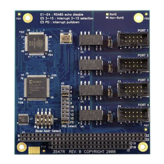
Page 26: Appendix E - Silk-Screen - 3547
Appendix E – Silk-Screen - 3547 © Sealevel Systems, Inc. 3547 Manual | SL9192 7/2021... -
Page 27: Appendix F - Compliance Notices
Always use cabling provided with this product if possible. If no cable is provided or if an alternate cable is required, use high quality shielded cabling to maintain compliance with FCC/EMC directives. © Sealevel Systems, Inc. 3547 Manual | SL9192 7/2021... -
Page 28: Warranty
Sealevel's commitment to providing the best I/O solutions is reflected in the Lifetime Warranty that is standard on all Sealevel manufactured I/O products. We are able to offer this warranty due to our control of manufacturing quality and the historically high reliability of our products in the field. Sealevel products are designed and manufactured at its Liberty, South Carolina facility, allowing direct control over product development, production, burn-in and testing.
Need help?
Do you have a question about the 3547 and is the answer not in the manual?
Questions and answers