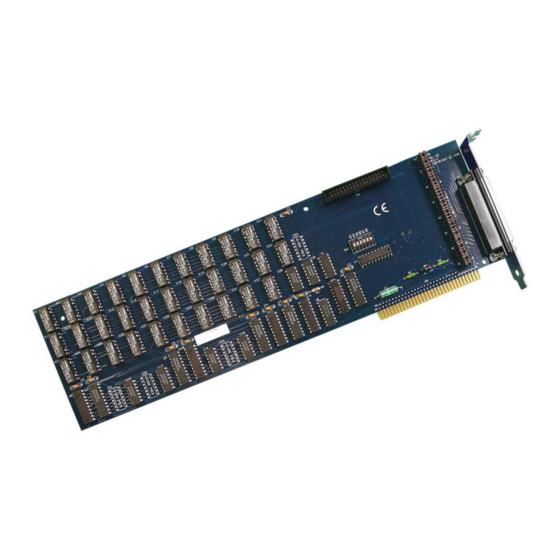
Summary of Contents for SeaLevel REL-32
- Page 1 ™ REL-32 USER’S MANUAL Part Number 3098 Sealevel Systems, Inc Phone: (864) 843-4343 155 Technology Place Fax: (864) 843-3067 P.O. Box 830 www.sealevel.com Liberty, SC 29657...
-
Page 2: Table Of Contents
Contents ................ 1 NTRODUCTION ................... 1 VERVIEW ’ ................1 NCLUDED ............. 1 ACTORY EFAULT ETTINGS ................2 ETUP ................2 DDRESS ELECTION ................3 PTIONS EADER JP1 ..................4 EADER P4............4 PTIONAL ABLE ONNECTOR ................5 NSTALLATION ..............5 OFTWARE NSTALLATION For Windows Users............... - Page 3 Figures Figure 1 - Address Selection Table ..............2 Figure 2 - DIP-Switch Illustration..............2 Figure 3 - Options Header P1-P3 ..............3 Figure 4 - Header JP1..................4 Figure 5 - DB-37 Connector Pin Assignments..........7 ©Copyright Sealevel Systems, Incorporated 2002a. All rights reserved.
-
Page 5: Introduction
The REL-32 is simple to operate. By writing instruction bytes to the I/O port addresses, the reed relays are energized or de-energized. What’s Included The REL-32 is shipped with the following items. If any of these items are missing or damaged, contact the supplier. •... -
Page 6: Card Setup
Card Setup Card Setup The REL-32 contains several jumper straps for each port which must be set for proper operation. Address Selection The REL-32 occupies 4 consecutive I/O locations. The DIP-switch (SW1) is used to set the base address for these locations. Be careful when selecting the base address as some selections conflict with existing PC ports. -
Page 7: Options Header
5V/12V Figure 3 - Options Header P1, P2 and P3 Note: The REL-32 is shipped with jumpers connecting the first 36 pins of headers P1 and P2. This connects the B-side of the relay banks to ground, which appear at the on-board DB-37. -
Page 8: Header Jp1
(CA-108) to pin header P4 with the colored edge of the ribbon cable attached to pin one. Removing all the jumpers connecting row P1 to P2 places the A-side of each relay at the on-board DB-37 and the B-side at the optional cable’s DB-37. Sealevel Systems REL-32 Page 4... -
Page 9: Installation
Installation Installation The REL-32 can be installed in any of the PC expansion slots. The REL-32 contains a DIP-switch (SW1) which must be set prior to installation. 1. Turn off PC power. Disconnect the power cord. 2. Remove the PC case cover. -
Page 10: Technical Description
Technical Description Technical Description The REL-32 Relay Output Adapter provides four parallel input/output (I/O) ports. The ports are organized as ports A, B, C and D and are reed relay output ports. Features • Selectable I/O port addressing from 200H - 3F8H •... -
Page 11: Connector Pin Assignments
Common 1 Common 3 Figure 5 - DB-37 Connector Pin Assignments In the REL-32 adapter’s default setting, all relay connections appear at the on-board DB-37. Note: Off-board and on-board pin connections are identical except that commons 2, 3, and 4 do not appear on the B-side connector. -
Page 12: Programming
#0, the second port is #1, the third #2, and so on. Due to the fact that the 3098 has no inputs the relative and absolute address for each relay are the same. Sealevel Systems REL-32 Page 8... - Page 13 27 ( R ) 28 ( R/W ) 28 ( R ) 29 ( R/W ) 29 ( R ) 30 ( R/W ) 30 ( R ) 31 ( R/W ) 31 ( R ) Sealevel Systems REL-32 Page 9...
-
Page 14: Direct Hardware Control
Decimal 300 (Base + 0) Relay 1- Relay 8 301(Base + 1) Relay 9 - Relay 16 302 (Base + 2) Relay 17 - Relay 24 303 (Base + 3) Relay 25 - Relay 32 Sealevel Systems REL-32 Page 10... -
Page 15: Specifications
Greater than 150,000 hours. (Calculated) Physical Dimensions Board length 13.33 inches (33.85 cm) Board Height including Goldfingers 4.2 inches (10.66 cm) Board Height excluding Goldfingers 3.9 inches (9.906 cm) Note: Please see Appendix D for board layout and dimensions. Sealevel Systems REL-32 Page 11... -
Page 16: Appendixa - Troubleshooting
1. Identify all I/O adapters currently installed in your system. This includes your on-board serial ports, controller cards, sound cards etc. 2. Configure your Sealevel Systems adapter so that there is no conflict with currently installed adapters. No two adapters can occupy the same I/O address. -
Page 17: Appendixb - How T O Get Assistance
3. Sealevel Systems maintains a forum on CompuServe providing utilities and new product information. This forum is accessed by typing “GO Sealevel” at the command prompt. 4. Technical support is available Monday to Friday from 8:00 a.m. -
Page 18: Appendixc - Electrical Interface
Contact Resistance, Initial: .15 Ohms • Rated Life: Low Load: 200 Million Closures Maximum Load: 100 Million Closures • Contact Speed: Operate: .5 mSec Release: .5 mSec Bounce: .5 mSec • Maximum Operating Speed: 600 Hertz Sealevel Systems REL-32 Page 14... -
Page 19: Appendixd - Silk -Screen
Appendix D - Silk-Screen Appendix D - Silk-Screen 4.2" 13.33" 3.9" Sealevel Systems REL-32 Page 15... -
Page 20: Appendixe - Schematic
Appendix E - Schematic Appendix E - Schematic Sealevel Systems REL-32 Page 16... - Page 21 Appendix E - Schematic Sealevel Systems REL-32 Page 17...
- Page 22 Appendix E - Schematic Sealevel Systems REL-32 Page 18...
- Page 23 Appendix E - Schematic Sealevel Systems REL-32 Page 19...
- Page 24 Appendix E - Schematic Sealevel Systems REL-32 Page 20...
- Page 25 Appendix E - Schematic Sealevel Systems REL-32 Page 21...
-
Page 26: Warranty
Should this product fail to be in good working order at any time during this period, Sealevel Systems will, at it's option, replace or repair it at no additional charge except as set forth in the following terms. This warranty does not apply to products damaged by misuse, modifications, accident or disaster.


Need help?
Do you have a question about the REL-32 and is the answer not in the manual?
Questions and answers