
Related Manuals for SeaLevel C4-104


Summary of Contents for SeaLevel C4-104
- Page 1 C4-104 User Manual | 3520, 3521, 3522 © Sealevel Systems, Inc. 3520, 3521, 3522 Manual | SL9054 12/2022...
-
Page 2: Table Of Contents
APPENDIX C – ELECTRICAL INTERFACE ......................17 APPENDIX D – PC/104 ............................19 APPENDIX E – SILK SCREEN ..........................20 APPENDIX F – COMPLIANCE NOTICES ......................21 WARRANTY ................................ 22 © Sealevel Systems, Inc. 3520, 3521, 3522 Manual | SL9054 12/2022... -
Page 3: Introduction
Introduction Overview The Sealevel Systems C4-104 series provides four selectable RS-232 or RS-422/485 serial I/O ports for your PC/104 application. Factory Default Settings The C4-104 factory default settings are as follows: Base Address Port 1 Port 2 Port 3 Port 4... -
Page 4: Before You Get Started
Before You Get Started What’s Included The C4-104 is shipped with the following items. If any of these items are missing or damaged, contact the supplier. • (1) C4-104 Serial Interface Adapter • (4) DB-9 Cable Assemblies • (1) Nylon Hardware Kit... -
Page 5: Card Setup
The C4-104 occupies four port addresses with each port occupying 8 consecutive I/O locations. A DIP switch (SW1) is used to set the port address options for the C4-104. Be careful when selecting the port addresses as some selections may conflict with existing ports. The following table shows the addressing options available with the standard PAL. - Page 6 With the jumper installed, RTS enables the RS-485 driver. Removing the jumper enables the driver regardless of RTS. The jumper should be installed for a 2/4 wire RS-485 application where the C4-104 is acting as a polled node on a multi-drop network. Remove the jumper if you are using a point to point RS- 422 application such as Programmable Logic Controllers (PLC's), etc.
- Page 7 Figure 4 - Headers E7 and E8 - RS-485 Enable and Echo Selection Interface Selection Due to the versatility of the C4-104, a wide range of interface configuration options is available to the end user. Please use this section as a guide in configuring your board to provide the interface you require.
- Page 8 Combined RS-232 & RS-422/485 Please use the following table as a guide in configuring the C4-104 in this manner. Configuration Drivers Headers E5 and E6 Ports 1 & 2 RS-232 U2 & U5 Installed E6 jumpers Removed Ports 3 & 4 RS-422 U1 &...
-
Page 9: Software Installation
6. The software is now installed, and you can proceed with the hardware installation. Linux Refer to the Linux.serial.readme file found in the Sealevel Systems Linux SeaCOM software. This file contains valuable information on installing your adapter in the various Linux releases. Also in this sub- directory is the Linux SerialHOWTO. - Page 10 Refer to the QNX6\Install.readme file in Sealevel System’s SeaCOM software. This file contains valuable information on installing your adapter in the QNX6 Neutrino OS, as well as the files required to ensure a flawless implementation. Also provided are implementation instructions for QNX4. These are found in in a file called - QNX4\QNX_COM.txt.
-
Page 11: Physical Installation
Do not install the Adapter in the machine until the software has been fully installed. Extreme care should be taken when installing the C4-104 to avoid causing damage to the connectors. After the adapter is installed, connect your I/O cables to J1-J4. Please note these headers are keyed so that pin 1 of the cable matches pin 1 of the connector. -
Page 12: Technical Description
Technical Description The C4-104 provides four RS-232 or RS-422/485 serial ports, utilizing a 16554 UART. This chip features programmable baud rates, data format, interrupt control and a 16-byte input and output FIFO. This UART is essentially four 16550 compatible UARTs in a 68 pin PLCC package. - Page 13 The Status Port is located at Base+7 on each port (example: Base=280 Hex, status port=287, 28F, 297, and 29F Hex. All four status ports on the C4-104 are identical, so any one of the four can be read. Example: This indicates that Port 2 has an interrupt pending.
-
Page 14: Specifications
10 to 90% R.H. Non-Condensing Manufacturing All Sealevel Systems Printed Circuit boards are built to UL 94V0 rating and are 100% electrically tested. These printed circuit boards are solder mask over bare copper or solder mask over tin nickel. Power Consumption... -
Page 15: Appendix A - Troubleshooting
No two adapters can occupy the same I/O address. Make sure the Sealevel Systems adapter is using a unique IRQ The IRQ is typically selected via an on-board header block. Refer to the section on Card Setup for help in choosing an I/O address and IRQ. -
Page 16: Appendix B - How To Get Assistance
If possible, please have the adapter installed in a computer ready to run diagnostics. 3. Sealevel Systems provides an FAQ section on its web site. Please refer to this to answer many common questions. This section can be found at http://www.sealevel.com/faq.asp. -
Page 17: Appendix C - Electrical Interface
0 (space) and -12 volts (-3 to -10 volts) denotes a binary 1 (mark). The RS-232 and the EIA/TIA-574 specification defines two type of interface circuits, Data Terminal Equipment (DTE) and Data Circuit-Terminating Equipment (DCE). The Sealevel Systems adapter is a DTE interface. RS-422 The RS-422 specification defines the electrical characteristics of balanced voltage digital interface circuits. - Page 18 (Tx+ to Rx+ and Tx- to Rx-). Four wire mode allows full duplex data transfers. RS-485 does not define a connector pin-out or a set of modem control signals. RS-485 does not define a physical connector. © Sealevel Systems, Inc. 3520, 3521, 3522 Manual | SL9054 12/2022...
-
Page 19: Appendix D - Pc/104
4 mA. Sealevel Systems has been a member of the PC/104 Consortium since its inception. Also Sealevel Systems has two members on the working group that is currently having the PC/104 bus approved by the IEEE as P996.1. -
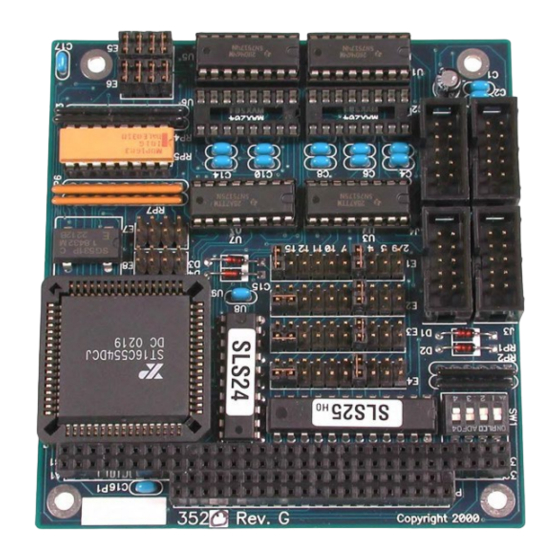
Page 20: Appendix E - Silk Screen
Appendix E – Silk Screen © Sealevel Systems, Inc. 3520, 3521, 3522 Manual | SL9054 12/2022... -
Page 21: Appendix F - Compliance Notices
Always use cabling provided with this product if possible. If no cable is provided or if an alternate cable is required, use high quality shielded cabling to maintain compliance with FCC/EMC directives. © Sealevel Systems, Inc. 3520, 3521, 3522 Manual | SL9054 12/2022... -
Page 22: Warranty
Sealevel's commitment to providing the best I/O solutions is reflected in the Lifetime Warranty that is standard on all Sealevel manufactured I/O products. We are able to offer this warranty due to our control of manufacturing quality and the historically high reliability of our products in the field. Sealevel products are designed and manufactured at its Liberty, South Carolina facility, allowing direct control over product development, production, burn-in and testing.
Need help?
Do you have a question about the C4-104 and is the answer not in the manual?
Questions and answers