Sign In
Upload
Manuals
Brands
NF Manuals
Amplifier
CA5350
NF CA5350 Manuals
Manuals and User Guides for NF CA5350. We have
1
NF CA5350 manual available for free PDF download: Instruction Manual
NF CA5350 Instruction Manual (110 pages)
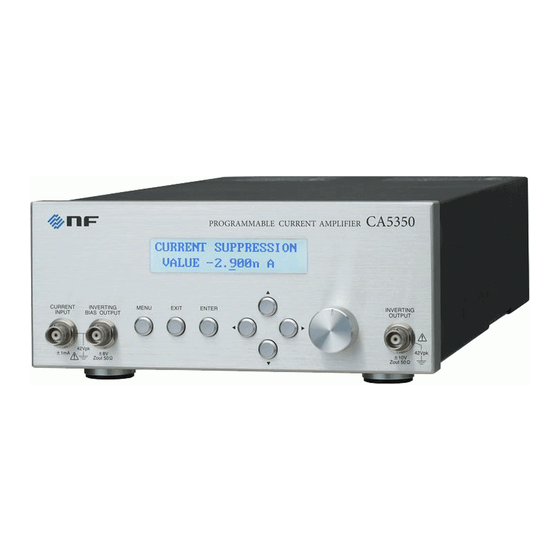
PROGRAMMABLE CURRENT AMPLIFIER
Brand:
NF
| Category:
Amplifier
| Size: 4 MB
Table of Contents
Outline
5
Table of Contents
9
Features
15
Applications
15
List of Functions
16
Principle of Operation
17
Figure 1-1 Block Diagram
17
Preparations before Use
19
Checking before Use
20
Table 2-1 Package Contents
20
Installation
21
General Precautions for Installation
21
Installation Conditions
21
Rack Mounting
22
Figure 2-1 Dimensional Drawing of Rack-Mount (EIA, for 1 Unit)
23
Figure 2-2 Dimensional Drawing of Rack-Mount (EIA, for 2 Units)
24
Figure 2-3 Dimensional Drawing of Rack-Mount (JIS, for 1 Unit)
25
Figure 2-4 Dimensional Drawing of Rack-Mount (JIS, for 2 Units)
26
Figure 2-5 Assembly Drawing of Rack-Mount Kit (EIA, for 1 Unit)
27
Figure 2-6 Assembly Drawing of Rack-Mount Kit (EIA, for 2 Units)
28
Figure 2-7 Assembly Drawing of Rack-Mount Kit (JIS, for 1 Unit)
29
Figure 2-8 Assembly Drawing of Rack-Mount Kit (JIS, for 2 Units)
30
Grounding and Power Supply Connection
31
Simplified Operation Check
33
Checking Operation and Display at Power on
33
Checking Key Operation and Response
33
Calibration
34
Panel Features and Basic Operations
35
Panel Component Names and Functions
36
Front Panel
36
Figure 3-1 Front Panel
36
Rear Panel
37
Figure 3-2 Rear Panel
37
Display at Power "ON" and Initial Setting
38
Initialization
38
Display at Power "ON
38
Table 3-1 Setting Items and Initial Values List
39
I/O Terminals
40
Figure 3-3 I/O Terminals
40
Figure 3-4 Input Terminal
41
Figure 3-5 Output Terminal
41
Figure 3-6 Output Polarity
41
Figure 3-7 DC Bias Voltage Output Terminal
42
I/O Connection
43
Connection of Optical Sensor (Photodiode)
44
Figure 3-8 Connection of Sensor Without Bias
44
Connection of Optical Sensor, Etc. (Photodiode)
44
Connection with Lock-In Amplifier, Etc
46
Connection with Lock-In Amplifier,Etc
46
Figure 3-11 When the Signal Source Is Grounded
46
Figure 3-12 When the Signal Source Cannot be Grounded
46
Operation Tree
47
Basic Operation Examples
49
Basic Key Operations
49
Simplified Operating Method When You Use Device for the First Time
51
Initialization
52
Basic Settings
53
Zero Check
53
Gain Setting
53
Figure 3-13 CA5350 Outline Block Diagram
54
Table 3-2 I/V Gain Settings and Auto-Filter Settings
55
Filter Setting
57
Advanced Operations
58
Zero Check
59
Cancelling the Dark Current of Sensor
60
Figure 4-2 Block Diagram of Current Suppression
60
Table 4-1 Current Suppression Setting Range and Resolution
60
Manually Setting the Current Value to be Cancelled
61
Automatically Deciding the Current Value to be Cancelled
61
Setting DC Bias Voltage
63
Figure 4-3 Connecting to DC Bias Voltage
63
Saving/Recalling the Settings
64
Self-Diagnosis
65
Adjusting the LCD Backlight Brightness
66
Checking Various Information
67
Checking the Version
67
Checking USB Related ID
67
Remote Control
68
Preparations before Use
69
Remote Control Interface Selection
69
Outline of USB
70
Preparation of Controller
70
Preparation of CA5350
70
USB Device Identification
70
Outline of GPIB
71
Preparation of Controller
71
Preparation of CA5350
71
Precautions on Use of GPIB
71
Basic Specifications of GPIB
72
Precautions on Communication
72
Switching between Remote State and Local State
73
Response to Interface Message
74
Table 5-1 Responses to Interface Messages
74
Service Request and Status Byte
75
Service Request
75
Status Byte
75
Table 5-2 Status Byte
75
Commands Explanation
76
Table 5-3 Priority of Execution of Commands
76
Description of Individual Command
78
Table 5-4 Header List
78
Multiline Interface Messages
89
Troubleshooting
90
Error Messages
91
Errors at Power on
91
Table 6-1 Error Message List at Power on
91
Errors at Panel Operation
92
Error During Operation
92
Errors in Remote Control
92
Table 6-2 List of Error Messages When Operating the Panel
92
Table 6-3 List of Error Messages During Operation
92
Table 6-4 List of Error Messages During Remote Control
92
When the Device Appears to be a Problem
93
Table6-5 When the Device Appears to be a Problem
93
Maintenance
94
Introduction
95
Daily Maintenance
95
Storage, Repackaging, and Transport
96
Checking the Version Number
96
Performance Testing
97
Current Suppression Setting Accuracy, Gain Accuracy
98
Output Offset Voltage
99
DC Bias Voltage Setting Accuracy
99
Calibration
100
Specifications
102
Input Section
102
Current Suppression Section
103
Amplifier Section
103
Output Section
104
General Information
105
External Dimensions
107
Figure 8-1 CA5350 External Dimensions
107
Advertisement
Advertisement
Related Products
NF CA5351
NF CA5360
NF BA4825
NF HSA4012
NF HSA4014
NF HSA4051
NF HSA4052
NF HSA42011
NF HSA42012
NF HSA42014
NF Categories
Amplifier
Measuring Instruments
AC Power Distribution
Portable Generator
Power Supply
More NF Manuals
Login
Sign In
OR
Sign in with Facebook
Sign in with Google
Upload manual
Upload from disk
Upload from URL