Table of Contents
Advertisement
Quick Links
Advertisement
Table of Contents

Subscribe to Our Youtube Channel
Related Manuals for Phoenix Contact FB-DP Series


Summary of Contents for Phoenix Contact FB-DP Series
- Page 1 Configuration and setup of FB-DP… and FB-HS... with ProfiTrace User manual...
- Page 2 User manual Configuration and setup of FB-DP… and FB-HS... with ProfiTrace 2015-07-13 Revision: This user manual is valid for: Designation Version Order No. FB-HS... 2316370 FB-HSB 2316379 FB-HSC 2316371 FB-DP-RPTR 2316373 FB-DP-RPTR/SC 2316374 FB-PA/SC 2316375 PHOENIX CONTACT 3389_en_A...
- Page 3 How to contact us Internet Up-to-date information on Phoenix Contact products and our Terms and Conditions can be found on the Internet at: phoenixcontact.com Make sure you always use the latest documentation.
- Page 4 The receipt of technical documentation (in particular user documentation) does not consti- tute any further duty on the part of Phoenix Contact to furnish information on modifications to products and/or technical documentation. You are responsible to verify the suitability and intended use of the products in your specific application, in particular with regard to observ- ing the applicable standards and regulations.
-
Page 5: Table Of Contents
2.2.2 Module status ..................13 System log......................14 Configuration ..........................15 General configuration ..................15 Network ....................... 16 IP address ......................17 Password ......................17 E-mail account..................... 19 Device management.................... 21 Output control...................... 22 User message ..................... 23 3389_en_A PHOENIX CONTACT... - Page 6 Creating a project using FdtCONTAINER............42 Technical appendix........................47 Bus parameters ....................47 Current consumption calculations ..............47 Voltage at the end of the segment ..............48 Directories and files .................... 48 Appendixes..........................49 List of figures ...................... 49 List of tables ....................... 51 PHOENIX CONTACT 3389_en_A...
-
Page 7: Fb-Hs
PA module, which means that the FB-PA/SC is always the start of a segment. The automatic termination cannot be disabled. Most installations will use only one connector. In that case it does not matter which connector is chosen. 3389_en_A PHOENIX CONTACT... -
Page 8: Cable Specifications
Spur lines Number of spur lines Length of the spur (Non-Ex) 25 to 32 Max 1 meter 19 to 24 30 meter 15 to 18 60 meter 13 to 14 90 meter 1 to 12 120 meter PHOENIX CONTACT 3389_en_A... -
Page 9: Connecting A Profibus/Dp Segment
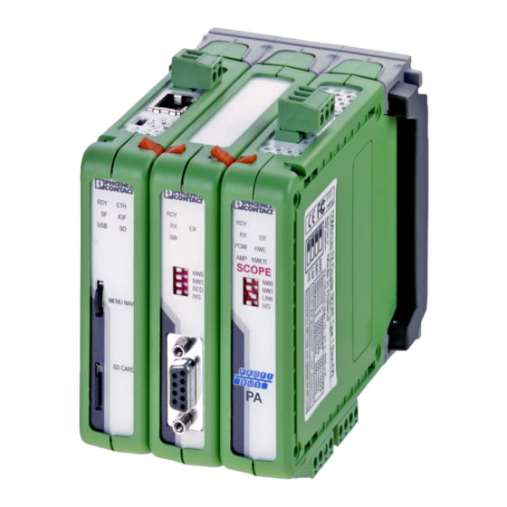
D-SUB 9 connector for the bus connection. The connectors are linked with each other, but it is not recommended to use them both. FB-HSB FB-PA/SC FB-DP-RPTR/SC FB-DP-RPTR NWER TERM SCOPE SCOPE LINK MENU NAV. SD CARD Figure 1-1 Repeater connection topologies 3389_en_A PHOENIX CONTACT... -
Page 10: Screw Terminals
When the D-SUB 9 connector is utilized and located at the end of the segment, it is recommended to use the termination on the D-SUB 9 connector rather than on the repeater module. Use a 2.5 mm (0.4 mm maximum) screwdriver to connect the PROFIBUS cable to the repeater modules. PHOENIX CONTACT 3389_en_A... -
Page 11: Termination Switch
Termination should be activated for modules located at the end of network segment. / S C - R P - D P M IN Figure 1-2 Termination switch The built-in termination provides resistances of 390/220/390 Ω between the conductors. 3389_en_A PHOENIX CONTACT... -
Page 12: Modes
To receive telegrams from a PLC or DCS in Link mode, you need to install another module in the backplane. This module can be any PROFIBUS DP interface card. Set this DP card to the same network as the PA module. PHOENIX CONTACT 3389_en_A... -
Page 13: Coupler Mode
When using software for configuration, the DIP switches do not have to be set. 1.5.2 Redundancy (RED) Set this DIP switch to enable the redundancy group for the channel. Redundancy LEFT RIGHT When using software for configuration, the DIP switches do not have to be set. 3389_en_A PHOENIX CONTACT... -
Page 14: Hardware Or Software Settings (H/S)
If the channel recognizes valid PROFIBUS messages from one or more connected devices, the RX LED of this channel should flash and the ER LED should be off. When the termination of a specific channel is set to on, the SWx LED should be on. PHOENIX CONTACT 3389_en_A... -
Page 15: Web Server
The initial view of the web server shows the status screen with all system devices. The web server page has three areas: the header, page list for navigation, and information/configuration screen. Header Page list Information/Configuration Figure 2-1 Web server page construction 3389_en_A PHOENIX CONTACT... -
Page 16: Status
Any changes in the modules will be immediately visible on the “Status” page. Figure 2-2 “Status” page The top of the “Status” page displays network and site information in the header. A custom user message can be displayed (see “General configuration” on page 15). PHOENIX CONTACT 3389_en_A... -
Page 17: Module Status
Web server 2.2.2 Module status Each name in the list of connected modules is a link that opens the status page for that particular module. Figure 2-3 Module status showing “Head station status” page 3389_en_A PHOENIX CONTACT... -
Page 18: System Log
The system log will continue to save events until it runs out of memory, which is approximately 1000 events. At that point, the oldest events are overwritten. The system log can also be cleared. Click the “Clear” button to delete all currently saved events. PHOENIX CONTACT 3389_en_A... -
Page 19: Configuration
1 second. If the bandwidth is limited, it is recommended to increase this time or uncheck the “Automatic refresh” box. Click the “Website start page” drop-down menu to select the initial page displayed when browsing to the Head Station IP address. The options are: – Main Status 3389_en_A PHOENIX CONTACT... -
Page 20: Network
This makes it possible to create a multiplexed system, or temporarily remove certain slaves from the PROFIBUS network. DIP switch settings are always primary to software settings. Figure 3-2 “Network configuration” page PHOENIX CONTACT 3389_en_A... -
Page 21: Ip Address
The FB-HS... supports two password levels: – Admin password: Provides full access to the web server. This must be set before the user password can be set. – User password: Limited to read-only information. 3389_en_A PHOENIX CONTACT... -
Page 22: Change Password" Page
If more than one person has access to the network, configure the Admin password. Follow recommended password best practices: • Activate the passwords immediately after installation. • Use different passwords at the administrator and user levels. PHOENIX CONTACT 3389_en_A... -
Page 23: E-Mail Account
Simply entering an e-mail address will not result in e-mail notifications. The SMTP server must support unencrypted connections as the FB-HS... does not support encrypted connections, such as SSL/TLS. The DNS address must be modified according to the DNS addresses of your Internet provider. 3389_en_A PHOENIX CONTACT... - Page 24 Check the e-mail settings and generate a test e-mail. Enter only one e-mail address in the “To” field when troubleshooting. – If the test e-mail works, verify that the “Event configuration” page is correctly enabled and an event has been triggered. PHOENIX CONTACT 3389_en_A...
-
Page 25: Device Management
Click the “Restore settings to factory defaults” button to reset the FB-HS... to the factory defaults. Click the “Restart the device” button to perform a soft restart, which does not require the need to physically reapply power. 3389_en_A PHOENIX CONTACT... -
Page 26: Output Control
The next column allows selection of the I/O point. The status of the specific I/O point is displayed as either On or Off. In the “Action” column, select “Profibus event”, and then select the criteria required to trigger the event. PHOENIX CONTACT 3389_en_A... -
Page 27: User Message
Configuration User message A custom user message can be entered and viewed when logged into the FB-HS... “Status” page. Figure 3-8 “User message” page 3389_en_A PHOENIX CONTACT... - Page 28 FB-HS... PHOENIX CONTACT 3389_en_A...
-
Page 29: Profitrace Oe
GSD files describes the capabilities of a device, and is shipped with each device. They can also be downloaded from the www.profibus.com website or from the device manufacturer’s website. The “Display Legend” dialog box appears explaining the meaning of the colors in more detail. Figure 4-1 “Live list” page 3389_en_A PHOENIX CONTACT... -
Page 30: Gsd Library
Figure 4-2 “Statistics” page The “Statistics” page provides a quick view into the data without the need for a detailed examination of messages or difficult operations to ensure the quality of the installation. PHOENIX CONTACT 3389_en_A... -
Page 31: Channel List
The following event automatically starts a message recording again. When the unit is first purchased or reset to the defaults, it automatically triggers the “Lost” statistic. The user can change the settings during operation. 3389_en_A PHOENIX CONTACT... -
Page 32: Message Recording" Page
The .ptc files are stored on the SD card. The .ptc files can be opened with ProfiTrace 2.5.3 and higher. PHOENIX CONTACT 3389_en_A... -
Page 33: Network Events
Network events The network event log shows all the processor activity of the head station and network and records any status changes. The event log can be viewed using a web browser. Figure 4-5 “Network event log” page 3389_en_A PHOENIX CONTACT... -
Page 34: Events
A check box allows each event to be independently configured to be either sent to an e-mail account or listed in the log file. The Interval time can be set from one minute to 365 days. Check boxes allow all events to be selected or deselected. PHOENIX CONTACT 3389_en_A... -
Page 35: Tagging Devices
Module tag names are also displayed in drop-down menus to modules and in tables on the following pages: – Oscilloscope images – Oscilloscope error images – Oscilloscope configuration – Bar graphs – PA measurements – Network configuration – Output control configuration 3389_en_A PHOENIX CONTACT... - Page 36 FB-HS... PHOENIX CONTACT 3389_en_A...
-
Page 37: Profibus Modules
After opening the web page, all oscilloscope signals are displayed and updated live. The benefits of the Phoenix Contact devices with a built-in oscilloscope are: – You do not have to touch the installation. -
Page 38: Oscilloscope Images" Page
Click on the oscilloscope waveform image of a device to display the device’s signals in a new page. This opens/creates a new web page. The FB-HSB and FB-HSC head stations and FB.../SC modules are limited to differential measurements. PHOENIX CONTACT 3389_en_A... -
Page 39: Oscilloscope Errors
Figure 5-2 “Oscilloscope error images” page Up to 16 error messages can be stored in the head station memory. If there are more than 16 error images, click the “Refresh error images” button to update the view. 3389_en_A PHOENIX CONTACT... -
Page 40: Bar Graphs
0.25 and 1 V for PROFIBUS PA networks. When there are bus problems, the graph displays different voltage levels and the colors of the bars change. The bar graph feature is also helpful for detecting issues with segment termination. Figure 5-3 “Bargraph image” page PHOENIX CONTACT 3389_en_A... -
Page 41: Pa Measurements
This does not affect the communication. DC noise The DC noise indicates how much the voltage of the signal varies. If the noise is too high, it can influence the communication; it should not exceed 100 mV. 3389_en_A PHOENIX CONTACT... -
Page 42: Oscilloscope Configuration
FB-HS... Oscilloscope configuration The “Oscilloscope” page allows customizing of the oscilloscope functions. Figure 5-5 “Oscilloscope configuration” page The termination voltage limits can be adjusted, as well as the limits for PA segment alarming. PHOENIX CONTACT 3389_en_A... -
Page 43: Profitrace Statistics Summary
Watchdog has run out on a DP device and the master sends a Data Exchange output telegram. – Non-certified DP devices that do not support a specific service/command or cannot handle a command in time. External Diag All responses from Get Diagnostics requests from all masters. 3389_en_A PHOENIX CONTACT... - Page 44 PA networks) or too high (in PROFIBUS PA networks only). Redundancy Failure One of the redundant cables has failed. PA signal and levels PROFIBUS PA values, such as jitter, DC voltage, or DC noise out of range. PHOENIX CONTACT 3389_en_A...
-
Page 45: Commdtm
– Click the “Driver” drop-down menu and select a driver. It is recommended that the most recent driver be selected. – The “Serial Nr.” field can remain empty. Click the “OK” button to close the dialog box. 3389_en_A PHOENIX CONTACT... -
Page 46: Creating A Project Using Fdtcontainer
Refer to the manual of your FDT manager for details. Figure 6-3 “CommDTM/Device” dialog box Click the “Device” tab. Click the “Add...” button. Select Phoenix Contact DP-V1 Master in the device list. PHOENIX CONTACT 3389_en_A... - Page 47 CommDTM Click the “OK” button, and then double-click Phoenix Contact DP-V1 Master to open the “Bus Parameter” page. Figure 6-4 FdtCONTAINER “Parameters” dialog box In the “Device Summary” list, right-click the Phoenix Contact DP-V1 master and click “Parameters” from the context menu.
- Page 48 FB-HS... The FB-HS... is now set up as a DP-V1 master. To activate the connection to field devices, right-click the Phoenix Contact DP-V1 master, and click the “Connect” option. Figure 6-5 Connecting to devices A communication session is now active between the software to the device connected on the network.
-
Page 49: Network Scan
To initiate the scan, right- click the Phoenix Contact DP-V1 master and click the “Scan/Create” option. The head station will scan the entire PROFIBUS network for active PROFIBUS DP and PROFIBUS PA devices. - Page 50 FB-HS... PHOENIX CONTACT 3389_en_A...
-
Page 51: A Technical Appendix
Electronics, stated in the manual of the PA device) should also be calculated. The calculation for the current consumption is as follows: + ... + I where = Total current in a segment = Basic current of devices = Current of the Fault Disconnection Electronics 3389_en_A PHOENIX CONTACT... -
Page 52: A 3 Voltage At The End Of The Segment
File with GSD information for the Live list settings.ini Head station settings (IP address, name, location, etc.) .ptc ProfiTrace OE message-recoding files located in the “Busmon” directory .pkg Firmware files .csv Log files located in the “Log” directory PHOENIX CONTACT 3389_en_A... -
Page 53: Appendixes
Figure 4-3: “Device channel list” page ..............27 Figure 4-4: “Message recording” page ..............28 Figure 4-5: “Network event log” page ..............29 Figure 4-6: “Event configuration” page ..............30 Figure 4-7: “Tag-name configuration” page ............31 3389_en_A PHOENIX CONTACT... - Page 54 Figure 6-2: “Ethernet Connection Configurator” dialog box ........42 Figure 6-3: “CommDTM/Device” dialog box ............42 Figure 6-4: FdtCONTAINER “Parameters” dialog box .......... 43 Figure 6-5: Connecting to devices ................ 44 Figure 6-6: Network scan ..................45 PHOENIX CONTACT 3389_en_A...
-
Page 55: B 2 List Of Tables
Table 5-1: Summary of statistics and events monitored by ProfiTrace OE ... 39 Appendix A Table A-1: Bus parameters for PROFIBUS/PA (in bit times) ......... 47 Table A-2: SD card directory................. 48 Table A-3: File extensions..................48 3389_en_A PHOENIX CONTACT... - Page 56 FB-HS... PHOENIX CONTACT 3389_en_A...
Need help?
Do you have a question about the FB-DP Series and is the answer not in the manual?
Questions and answers