Table of Contents
Advertisement
Quick Links
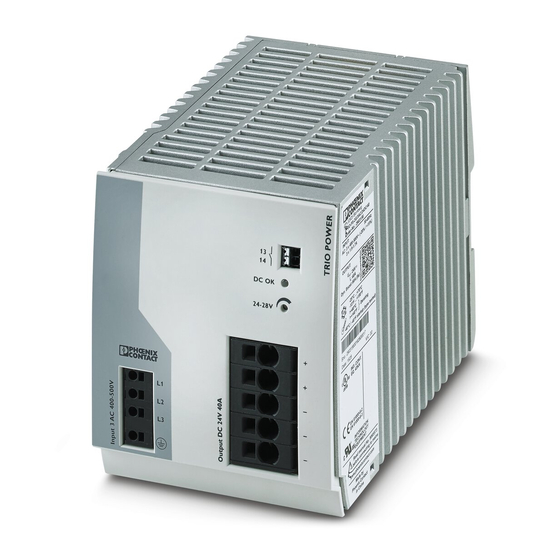
TRIO-PS-2G/3AC/24DC/40
Power supply unit
Data sheet
105907_en_00
1
Description
TRIO POWER - power supplies with standard functionality
The power supplies of the TRIO POWER family convince
due to their slim and robust design. The dynamic boost (1.5
x I
for 5 seconds) absorbs starting currents and short
N
overload situations securely during operation and without a
drop in output voltage. The push-in connection technology
on the front enables fast and tool-free wiring of the devices.
Features
–
Tool-free connection via push-in connection
technology
–
Safe operation, thanks to electrically and mechanically
robust design
–
Especially slim design
–
Worldwide use, thanks to wide-range input
–
Reliable starting of heavy loads, thanks to dynamic
boost (1.5 x I
for 5 seconds)
N
–
Simplified error diagnostics for remote signaling via DC-
OK signal contact
–
OVP (Over Voltage Protection) limits surge voltages to
≤30 V DC (EN 61131-2)
Make sure you always use the latest documentation.
It can be downloaded from the product at phoenixcontact.net/products.
© PHOENIX CONTACT
2017-08-02
Technical data (short form)
Input voltage range
Mains buffering
Nominal output voltage (U
Setting range of the output voltage
(U
)
Set
Nominal output current (I
Dynamic Boost (I
Output power (P
Output power (P
Efficiency
Residual ripple
MTBF (IEC 61709, SN 29500)
Ambient temperature (operation)
Dimensions W/H/D
Weight
3x400 V AC ... 500 V AC
-20 % ... +15 %
> 10 ms (400 V AC)
> 20 ms (480 V AC)
)
24 V DC ±1 %
N
24 V DC ... 28 V DC
)
40 A
N
)
60 A (5 s)
Dyn.Boost
)
960 W
N
)
1440 W
Dyn. Boost
typ. 93 % (400 V AC)
typ. 93.3 % (480 V AC)
≤ 50 mV
PP
> 1730000 h (25 °C)
> 1051000 h (40 °C)
> 510000 h (60 °C)
-25 °C ... 70 °C
-40°C (startup type tested)
> 60 °C Derating: 2.5 %/K
110 mm / 130 mm / 160 mm
2.6 kg
Advertisement
Table of Contents

Subscribe to Our Youtube Channel
Related Manuals for Phoenix Contact TRIO-PS-2G/3AC/24DC/40


Summary of Contents for Phoenix Contact TRIO-PS-2G/3AC/24DC/40
-
Page 1: Description
TRIO-PS-2G/3AC/24DC/40 Power supply unit Data sheet 105907_en_00 © PHOENIX CONTACT 2017-08-02 Description TRIO POWER - power supplies with standard functionality The power supplies of the TRIO POWER family convince Technical data (short form) due to their slim and robust design. The dynamic boost (1.5 Input voltage range 3x400 V AC ... -
Page 2: Table Of Contents
14 Output ............................14.1 Position of output terminals...........................18 14.2 Protection of the secondary side........................18 14.3 Output characteristic curve ...........................18 15 Dynamic boost .......................... 16 Signaling .................................19 16.1 DC OK-LED ..............................19 16.2 Floating signal contact ..........................19 105907_en_00 PHOENIX CONTACT 2 / 25... - Page 3 Position-dependent derating ........................21 18 Operating modes ........................18.1 Series operation ............................24 18.2 Parallel operation ............................24 18.3 Redundant operation............................ 24 18.4 Decoupling with diode module ........................24 18.5 Increasing power ............................25 105907_en_00 PHOENIX CONTACT 3 / 25...
-
Page 4: Ordering Data
With electronic locking of the set nominal currents. For installation on DIN rails. The range of accessories is being continuously extended. The current range of accessories can be found in the download area for the product. 105907_en_00 PHOENIX CONTACT 4 / 25... -
Page 5: Technical Data
The external backup fuse must be approved for the (AC) supply voltage used and the voltage level. Electric strength of the insulation Insulation voltage input/output ( IEC/EN 60950-1 ) 3 kV AC (type test) 1.5 kV AC (routine test) Production test 2.5 kV DC 105907_en_00 PHOENIX CONTACT 5 / 25... - Page 6 0.75 mm² ... 16 mm² Conductor cross section, flexible 0.75 mm² ... 10 mm² Stranded conductor cross section with ferrule 0.75 mm² ... 10 mm² Conductor cross section AWG 20 ... 4 Stripping length 18 mm 105907_en_00 PHOENIX CONTACT 6 / 25...
- Page 7 Maximum power dissipation in no-load condition typ. 14 W typ. 17 W Power loss nominal load max. typ. 70 W typ. 72 W Efficiency 400 V AC 480 V AC typ. 93 % typ. 93.3 % 105907_en_00 PHOENIX CONTACT 7 / 25...
- Page 8 Limitation of mains harmonic currents EN 61000-3-2 Rail applications EN 50121-4 Approvals UL Listed UL 508 UL/C-UL Recognized UL 60950-1 Current approvals/permissions for the product can be found in the download area under phoenixcontact.net/ products. 105907_en_00 PHOENIX CONTACT 8 / 25...
- Page 9 2 kV (Test Level 3 - 2 kV (Test Level 3 - asymmetrical) asymmetrical) Signal 1 kV (Test Level 3 - 2 kV (Test Level 3 - asymmetrical) asymmetrical) Comments Criterion B Criterion A 105907_en_00 PHOENIX CONTACT 9 / 25...
- Page 10 Radio interference voltage in acc. with EN 55011 EN 55011 (EN 55022) Class B, area of application: Industry and residential Emitted radio interference in acc. with EN 55011 EN 55011 (EN 55022) Class B, area of application: Industry and residential 105907_en_00 PHOENIX CONTACT 10 / 25...
-
Page 11: Safety Regulations And Installation Notes
1 (e.g., by line protection on the primary side). – All feed lines are sufficiently protected and dimensioned! – All output lines are dimensioned according to the maximum output current of the device or separately protected! – Sufficient convection is guaranteed! 105907_en_00 PHOENIX CONTACT 11 / 25... -
Page 12: High-Voltage Test (Hipot)
- Electrical equipment of machines) the power supply can be High-voltage disconnected during the high-voltage test and only installed tester once the high-voltage test has been completed. Signal contacts Green (optional) Potential 2 DC output circuit Blue Potential 2 105907_en_00 PHOENIX CONTACT 12 / 25... -
Page 13: Basic Circuit Diagram
Connection terminal block output voltage: Output DC +/- Potentiometer, output voltage: 24 V DC ... 28 V DC Signaling DC OK LED Floating signal contact: max. 30 V AC/DC, 100 mA Integrated universal snap-on foot 105907_en_00 PHOENIX CONTACT 13 / 25... -
Page 14: Cooling
To ensure sufficient wiring space to wire the power supply, we recommend a vertical minimum clearance from other devices of 50 mm. Depending on the cable duct used, a smaller clearance may be possible. 105907_en_00 PHOENIX CONTACT 14 / 25... -
Page 15: Device Dimensions
TRIO-PS-2G/3AC/24DC/40 10.2 Device dimensions DC OK 24-28V 23,5 Figure 6 Device dimensions 105907_en_00 PHOENIX CONTACT 15 / 25... -
Page 16: Mounting/Removal
To disconnect the wiring, take a suitable screwdriver and insert it into the opening for release. Then carefully pull the connecting cable out of the contact opening. Figure 10 Release connecting cable (push-in connection technology) Figure 8 Removing the DIN rail 105907_en_00 PHOENIX CONTACT 16 / 25... -
Page 17: Input
Opening the device or repairing it yourself is prohibited. (L3) Figure 13 Schematic diagram, switching the input terminals Figure 11 Network types 13.1 Position of input terminals Input Figure 12 Position of input terminals 105907_en_00 PHOENIX CONTACT 17 / 25... -
Page 18: Output
– = 1440 W dyn. BOOST have separate protection. The connecting cables on the secondary side should have large cross sections to keep the voltage drops in the cables as low as possible. 105907_en_00 PHOENIX CONTACT 18 / 25... -
Page 19: Dynamic Boost
Digital Input required for the release of thermal tension. The ratio of dynamic boost time and time for DI x thermal tension release always varies depending on load. DC OK 24-28V Figure 19 Wiring principle 105907_en_00 PHOENIX CONTACT 19 / 25... -
Page 20: Derating
100 % 60 °C 150 % 60 °C Dyn. 1000 2000 3000 4000 5000 H [m] Figure 21 Output power depending on the installation height 105907_en_00 PHOENIX CONTACT 20 / 25... -
Page 21: Position-Dependent Derating
The characteristic curve can be used to determine the maximal output power to be drawn for each ambient temperature for different mounting positions. Normal mounting position 1.5 x I [°C] Rotated mounting position 90° X-axis 1.5 x I [°C] 105907_en_00 PHOENIX CONTACT 21 / 25... - Page 22 TRIO-PS-2G/3AC/24DC/40 Rotated mounting position 180° X-axis 1.5 x I [°C] Rotated mounting position 270° X-axis 1.5 x I [°C] 105907_en_00 PHOENIX CONTACT 22 / 25...
- Page 23 TRIO-PS-2G/3AC/24DC/40 Rotated mounting position 90° Z-axis 1.5 x I [°C] Rotated mounting position 270° Z-axis 1.5 x I [°C] 105907_en_00 PHOENIX CONTACT 23 / 25...
-
Page 24: Operating Modes
(e.g., decoupling diode, DC fuse or circuit breaker). This prevents high return Figure 24 Schematic diagram, decoupling with diode currents in the event of a secondary device fault. module 105907_en_00 PHOENIX CONTACT 24 / 25... -
Page 25: Increasing Power
– Σ = 2 x I + – Figure 26 Schematic diagram of increased performance PHOENIX CONTACT GmbH & Co. KG • 32823 Blomberg • Germany 105907_en_00 25 / 25 phoenixcontact.com...
Need help?
Do you have a question about the TRIO-PS-2G/3AC/24DC/40 and is the answer not in the manual?
Questions and answers