Sign In
Upload
Download
Table of Contents
Contents
Add to my manuals
Delete from my manuals
Share
URL of this page:
HTML Link:
Bookmark this page
Add
Manual will be automatically added to "My Manuals"
Print this page
×
Bookmark added
×
Added to my manuals
Manuals
Brands
Elan Manuals
Controller
HC6
Installation manual
Elan HC6 Installation Manual
Hide thumbs
Also See for HC6
:
Quick install manual
(3 pages)
1
2
3
4
Table Of Contents
5
6
7
8
9
10
11
12
13
14
15
16
17
18
19
20
21
22
23
24
25
26
27
28
29
30
31
32
33
34
35
36
37
38
39
40
41
42
43
44
45
46
47
48
49
50
51
52
53
54
55
56
57
58
59
60
61
page
of
61
Go
/
61
Contents
Table of Contents
Troubleshooting
Bookmarks
Table of Contents
Organization
Preface
Purpose of this Manual
Safety Information
Table of Contents
Chapter 1: Introduction
The ELAN Story
HC6/HC12 Features
Applications
HC6/HC12 Front Panel Display
HC6/HC12 Rear Panel Connections
Chapter 2: HC6/HC12 System Design and Applications
Introduction
Pre-Wire
Applications
HC6 Controlling an ELAN M86A
HC12 Controlling an ELAN S86A and V85
HC12 Controlling an ELAN S128P with a C2 Communications Controller
HC6 Internal Player and IP Video Server
HC12 Controlling a Sunfire TGR-401 Receiver
Chapter 3: HC6/HC12 Connections
RS-232 Connections
RS-485 Connections
Vianet Connection
Relay Connections
Sense Input Connections
IR Output Connections
External IR Input Connection
Audio Output Connections
Internal Player Capacity
Component Video Input / Output Connections
Ethernet Connections
USB Connections
IR Link Connection
IR Link Connection Advanced Application
Chapter 4: Operation
Power Switch
Rear Panel Leds
Serial Ports
Vianet Ports
Ethernet Port
Chapter 5: Precision Panels
PPWM Precision Panel
IR Link
External IR in
IR Outputs
Sense Inputs
Relay Connections
RJ-45 Connections
PPIR Precision Panel
PPIS Precision Panel
PPRM Precision Panel
PPSP Precision Panel
PPVN Precision Panel
Chapter 6: Troubleshooting
General
Serial Devices
Vianet
Relays
Sense Inputs
IR Operation
Audio Outputs
Video
Ethernet
Appendix A: Network Information
IP Configuration
Port Forwarding
Appendix B: Rack Mounting
Specifications
Warranty
Advertisement
Quick Links
1
Hc6/Hc12 Features
2
Hc6/Hc12 Front Panel Display
3
Introduction
4
Ip Configuration
Download this manual
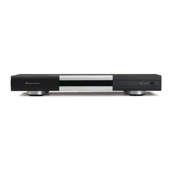
HC6/HC12
System Controller
INSTALLATION MANUAL
Table of
Contents
Previous
Page
Next
Page
1
2
3
4
5
Advertisement
Table of Contents
Need help?
Do you have a question about the HC6 and is the answer not in the manual?
Ask a question
Questions and answers
Related Manuals for Elan HC6
Controller Elan HC6 Quick Install Manual
(3 pages)
Controller Elan HC8 Quick Install Manual
(2 pages)
Controller Elan HC12 Installation Manual
(61 pages)
Controller Elan V883 Installation Manual
Elan home systems video controller installation manual v883 v series (32 pages)
Controller Elan S6 Brochure
Elan s6 av controllers: product brochure (8 pages)
Controller Elan EL-SC-100 Quick Install Manual
(17 pages)
Controller Elan EM78P156N Manual
8-bit micro-controller (57 pages)
Controller Elan gSC10 Quick Install Manual
(2 pages)
Controller Elan RS232 Installation Manual
Rs232 system controller (24 pages)
Controller Elan S6 Specifications
Integrated multi-zone controller (2 pages)
Controller Elan Z-600 Owner's Manual
Communications controller (16 pages)
Controller Elan gSC2 Quick Install Manual
(2 pages)
Controller Elan OLE XL Brochure & Specs
Film interactive touchpads (20 pages)
Controller Elan OLE XL Specifications
Film interactive touchpad with 2.1" oled display (2 pages)
Controller Elan OLE Specifications
Film interactive touchpad (2 pages)
Controller Elan C2 Communications Controller Installation Manual
Communications controller (73 pages)
This manual is also suitable for:
Hc12
Table of Contents
Print
Rename the bookmark
Delete bookmark?
Delete from my manuals?
Login
Sign In
OR
Sign in with Facebook
Sign in with Google
Upload manual
Upload from disk
Upload from URL


Need help?
Do you have a question about the HC6 and is the answer not in the manual?
Questions and answers