
Related Manuals for Elan RS232


Summary of Contents for Elan RS232
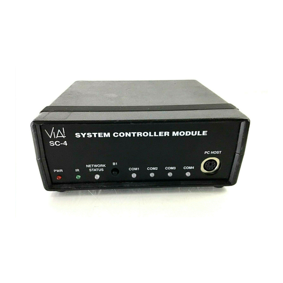
- Page 1 SC-4 4 RS232 SYSTEM CONTROLLER INSTALLATION MANUAL See SC-4 Programming Manual for Programming Instructions P/N 40615-143-24 (B)
- Page 2 O O N N T T E E N N T T S S INTRODUCTION................3 FEATURES ..................3 SYSTEM INTEGRATION ............4 Series, HD Series, and Stand-Alone ......4 CONNECTIONS ................4 System Wire Run Specifications/VIA!Net Overview ..5 VIA!Net Repeaters..............7 USING PVIA WALL PLATES ............8 SYSTEM CONNECTIONS ............9 PVIA-1 with an ELAN Z System ........9 PVIA-1 with an ELAN HD Series System ......10...
- Page 3 N N T T R R O O D D U U C C T T I I O O N N The SC-4 System Controller is an RS232 system network interface. It enables as many as 30 VIA! Panels to access up to four RS232 controllable sub-systems including lighting, security, climate control, and A/V components.
- Page 4 As an interface between the VIA! Panels and enables system information to be fed back from the Z System using a PZ6 Precision Panel. To enable the VIA! Panels in your Z System to issue serial commands to RS232 controlled sub-systems.
- Page 5 V V I I A A ! ! N N e e t t O O v v e e r r v v i i e e w w The communication link between the SC-4 and all the VIA! Touch Panels in a system is called the 'VIA!Net'.
- Page 6 --------------- Total = 2000’ Figure 2 - A BASIC VIA!Net 2000ft. MAX combined wire length. Total length of wire run to all VIA!s in the system DOES NOT exceed 2000ft, therefore VIA!Net Repeaters are not needed. The length of wire run to any single VIA! Panel MUST NOT exceed 1000ft PVIA and SC-4 VIA! #1 = 500’...
- Page 7 On the left side of the graphic below is a CAT5 pigtail (included) used to connect the VIA!Net Repeater to the back of a PVIA Wall Plate. NOTE: This connection is wired exactly the same way as you would normally punch down a VIA! Panel to a PVIA Wall Plate using CAT5.
- Page 8 Z Z S S e e r r i i e e s s , , H H D D S S e e r r i i e e s s , , a a n n d d S S t t a a n n d d A A l l o o n n e e S S y y s s t t e e m m s s The graphics in the following pages illustrate how to connect VIA! Panels to PVIA-1, PVIA-4, PVIA-10, PZ6, and PHD12 products. Additionally, wiring configurations illustrating how to directly connect to a Z630 PreAmp Controller or HD Series Dual Zone Card are included.
- Page 9 Y Y S S T T E E M M To SC-4 Figure 7 - An in-wall VIA! Panel powered by a PVIA-1 and connected to a PZ6 Precision Panel to interface with an ELAN Z!Series system (Zone 5 IR connections shown).
- Page 10 Y Y S S T T E E M M To SC-4 Figure 9 - An in-wall VIA! Panel powered by a PVIA-1 and connected to a PHD12 Precision Panel to interface with an ELAN HD Series system. NOTE: the SC-4 is connected to the PVIA-1 In-Wall version’s “To SC-4” output.
- Page 11 Stand-Alone system. NOTE: the SC-4 is connected to the PVIA-1 In-Wall version’s “To SC-4” output. Although not shown - the SC-4’s power supply may be used to power both the SC-4 and a single VIA! Panel. Connect...
- Page 12 O O N N T T I I N N U U E E D D Figure 13 - A VIA! Valet powered by a PVIA-1 Valet version and connected to a PVIA-1 In-Wall version. The PVIA-1 In-Wall is then connected to a PZ6 or PHD12 to be interfaced with an ELAN Z or HD Series system.
- Page 13 SC-4 Figure 16b Figure 16a - A VIA! Panel mounted in a wall and connected to the PVIA-4’s “VIA! #1” Punchdown and Power terminals. Figure 16b - A VIA! Valet connected to a PVIA-1 Valet version, then connected to a PVIA-4’s “VIA #1”...
- Page 14 SC-4 Connecting a PVIA-4 to a Z630 WITHOUT a PZ6 Precision Panel Figure 17 - The connections between VIA! Panels, a PVIA-4, and an ELAN Z System with and without a PZ6 Precision Panel. (Use of a PZ6 Precision Panel is suggested).
- Page 15 W W I I T T H H A A N N Y Y S S T T E E M M Figure 18 - As many as four in-wall VIA! Panels powered by a PVIA4 and connected to a PHD12 Precision Panel to interface with an ELAN HD Series system.
- Page 16 COMM Ports x4 and / or Figure 20 - Connecting as many as ten VIA! Panels to a PVIA-10 for power, then paralleling data connections to a PHD12 or PZ6 for control of an ELAN Z or HD Series system.
- Page 17 Figure 23 - Linking three PVIA-10’s together to enable the maximum of 30 VIA! Panels to be linked to a single SC-4. NOTE: Any of the 485+/- connections belonging to any VIA! Panel (1-10, 11-20, or 21-30) on each PVIA-10 may be used to link the 485 +/- “busses”...
- Page 18 C C O O N N T T I I N N U U E E D D REAR VIEW! Figure 24 - As many as 10 VIA! Panels may be connected to a PVIA-10 Precision Panel. SC-4 Figure 25 - A VIA! Valet powered by a PVIA-1 and connected to a PVIA-10 to accommodate the necessary data connections.
- Page 19 Y Y S S T T E E M M SC-4 Figure 26 - As many as 10 VIA! Panels connected to a PVIA-10 for power, with data connections paralleled between the PVIA-10 and the PZ6 for connection to an ELAN Z Series system. NOTE: The SC-4 may be powered by the PVIA-10’s power suppy using the RJ45-to-RJ45 connection between...
- Page 20 C C O O N N T T I I N N U U E E D D SC-4 Figure 28 - Connection of as many as 10 VIA! Panels to a PVIA-10 (for power). The PVIA-10 is then connected directly to a Z630 WITHOUT a PZ6 Precision Panel.
- Page 21 Y Y S S T T E E M M SC-4 Figure 28 - As many as 10 VIA! Panels connected to a PVIA-10 for power. Data connections are then paralleled between the PVIA-10 and the PHD12 for connection to an ELAN HD Series system. NOTE: The SC-4 may be powered by the PVIA-10’s power suppy using the RJ45 -to-RJ45 connection between...
- Page 22 O O N N F F I I G G U U R R A A T T I I O O N N S S The rear panel of the SC-4 features an ELAN RS232 OUT port. This port facilitates serial control of ELAN products without having to sacrifice one of the four DB9 COMM ports.
- Page 23 O O N N F F I I G G U U R R A A T T I I O O N N S S O O N N T T Figure 32 - The SC-4’s ELAN RS232 OUT terminal used to enable control of an ELAN SR-1 Sense/Relay Module. A maximum of two SR-1s may be connected using the SR-1’s RS232 IN/THRU terminals.
- Page 24 O O N N F F I I G G U U R R A A T T I I O O N N S S O O N N T T Figure 34 - The ELAN RS232 OUT terminal used to enable control of as many as two ELAN SR-1 Sense/Relay Modules, three ELAN Z880 Video Controllers, and/or an HD Series MCU’s HDC2040 Automation Card using...
Need help?
Do you have a question about the RS232 and is the answer not in the manual?
Questions and answers