
Subscribe to Our Youtube Channel
Related Manuals for Quantum QT-740


Summary of Contents for Quantum QT-740
- Page 1 Models QT-740 and QT-750 Fixed/Elevating Float-Top Radiographic Tables Operator’s Manual Manual Part No. DC30-006 Revision A...
- Page 2 This manual is copyrighted and all rights are reserved. No portion of this document may be copied, photocopied, reproduced, translated, or reduced to any electronic medium or machine readable form without prior consent in writing from Quantum Medical Imaging, LLC.
-
Page 3: Revision History
Revision History REVISION DATE TYPE OF MODIFICATION 11/01/00 Initial Release. Page Page Page Number Number Number i - iv 1 - 30 Models QT-740 & QT-750 - Operator’s Manual... - Page 4 Revision History THIS PAGE INTENTIONALLY LEFT BLANK Models QT-740 & QT-750 - Operator’s Manual...
- Page 5 Table of Contents Table of Contents Chapter 1, Safety Notices Chapter 2, General Information Chapter 3, Operation Chapter 4, User Maintenance Chapter 5, Warranty Information Models QT-740 & QT-750 - Operator’s Manual...
- Page 6 Table of Contents THIS PAGE INTENTIONALLY LEFT BLANK Models QT-740 & QT-750 - Operator’s Manual...
-
Page 7: Safety Notices
Chapter SAFETY NOTICES... -
Page 9: X-Ray Protection
Chapter 1 Safety Notices WARNING Quantum Medical Imaging, LLC disclaims all responsibility from any injury resulting from improper application of this equipment. This equipment is sold to be used exclusively under the prescribed direc- tion of a person who is licensed by law to operate equipment of this nature. -
Page 10: Regulatory Compliance
Chapter 1 Safety Notices REGULATORY COMPLIANCE This certified Quantum Medical Imaging, LLC medical device has been designed, manufactured, and calibrated to comply with governing Federal Regulations 21 CFR Subchapter J and the performance standards attendant thereto. Upon installation, all certified products require the filing of Form FD-2579 "Report of Assembly of a Diag- nostic X-ray System"... - Page 11 The following symbols may be used for marking on this equipment or equipment doc- umentation: Earth (ground) Type B Equipment Protective Earth (ground) Attention, consult accompanying documents Dangerous Voltage Enable tabletop float (releases transverse and longitudinal locks) Enable Tabletop Up Motion Enable Tabletop Down Motion Models QT-740 & QT-750 - Operator’s Manual...
- Page 12 Chapter 1 Safety Notices THIS PAGE INTENTIONALLY LEFT BLANK Models QT-740 & QT-750 - Operator’s Manual...
- Page 13 Chapter GENERAL INFORMATION...
-
Page 15: Chapter 2 General Information
The user should The key features of the Model QT-740 and QT-750 radiographic tables are as follows: read this man- ual in its en- •... -
Page 16: Main Components
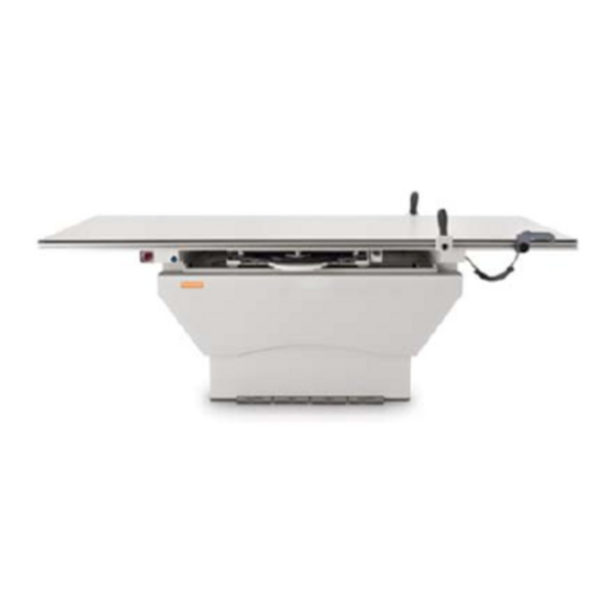
Foot Pedal/FLOAT Push Button Inhibit Switch Base Foot Pedal(s) - Float (Model QT-740) Float, Up and Down (Model QT-750) Float Push Button Switch Patient Handgrips Image Receptor Lock Release Switch Figure 1. Radiographic Table Main Components Models QT-740 & QT-750 - Operator’s Manual... -
Page 17: Operation
Chapter OPERATION... - Page 19 Chapter 3 Operation OVERVIEW To provide precise patient positioning, Model QT-740 and QT-750 radiographic tables feature a tabletop that "floats" in four directions; transversely (forward and backward) and longitudinally (left and right). Model QT-750 has the additional capability of tabletop elevation (i.e., the tabletop can be raised and lowered to facilitate patient transfer on and off the table).
- Page 20 FLOAT FOOT PEDAL Figure 4. Model QT-740 FLOAT Foot Pedal Control Models QT-740 and QT-750 both feature a "floating" tabletop. With the "float- top" function activated, both transverse and longitudinal positioning of the patient is enabled. To operate the float-top function, proceed as follows:...
- Page 21 For safety purposes, an Emergency Stop Switch (see Figure 6) immediately removes power from the tabletop up/down motor when activated. Rotating the Emergency Stop Switch knob 1/4-turn counterclockwise releases the Emergency Stop Switch and restores power. Models QT-740 & QT-750 - Operator’s Manual...
-
Page 22: Emergency Stop Switch
RAISING THE TABLETOP safeguard against per- 1. Press the UP foot pedal (see Figure 5) to raise the tabletop to the sonal injury. desired height. 2. Proceed with examination. Models QT-740 & QT-750 - Operator’s Manual... - Page 23 To prevent accidental activation of the foot pedal controls (i.e., FLOAT foot pedal on Model QT-740 and FLOAT, UP, and DOWN foot pedals on Model QT-750) and the FLOAT push button, a Foot Pedal Disable Switch is provided. This switch is located below the front table rail on the left end of the table (see Figure 6).
-
Page 24: Lock Handle
8. While pushing front grip against cassette, turn cassette lock han- dle to lock position. 9. Push tray into receptor. The cassette is now in exposure position. SLIDE GUIDES CASSETTE GRIP LOCK HANDLE TRAY HANDLE Figure 8. Midwest Cassette Film Tray Models QT-740 & QT-750 - Operator’s Manual... - Page 25 5. Insert cassette into tray (back end first). Center it using center- ing label. 6. Slide clamp forward pushing clamp firmly against cassette. 7. While pushing clamp against cassette, press clamp handle down. CLAMP HANDLE TRAY HANDLE Figure 9. Poersch Cassette Film Tray Models QT-740 & QT-750 - Operator’s Manual...
- Page 26 Chapter 3 Operation THIS PAGE INTENTIONALLY LEFT BLANK Models QT-740 & QT-750 - Operator’s Manual...
-
Page 27: Maintenance
Chapter USER MAINTENANCE... -
Page 29: Chapter 4 User Maintenance
2. Pull the cassette tray out by the handle until it stops. 3. Grasp both sides of the tray with your right hand placed near the table and your left hand towards the tray front. Models QT-740 & QT-750 - Operator’s Manual... - Page 30 4. Locate the square block at the back right side of the cassette tray. A spring-loaded plate is on the front side of the block. While pressing the plate, pull the tray out from the Receptor Cabinet. Models QT-740 & QT-750 - Operator’s Manual...
- Page 31 Chapter WARRANTY INFORMATION...
-
Page 33: Chapter 5 Warranty Information
Chapter 5 Warranty Information WARRANTY STATEMENT Quantum Medical Imaging, LLC (herein known as “QMI”) warrants to buyer that any new product manufactured by QMI will be free from defects in material and manufac- turing and conform substantially to applicable specifications in effect on the date of shipment when subjected to normal, proper and intended usage by properly trained personnel. -
Page 34: Warranty Exclusions
This warranty extends only to the origi- nal purchase and is not transferable unless authorized in writing by Quantum Medical Imaging. -
Page 35: Buyer's Remedies
Chapter 5 Warranty Information BUYER’S REMEDIES If Quantum Medical Imaging determines that any Product fails to meet any warranty during the applicable warranty periods, Quantum Medical Imaging shall correct any such failure as follows: A) By repairing, adjusting, or replacing any defective or non-conforming Parts or Products. - Page 36 Chapter 5 Warranty Information THIS PAGE INTENTIONALLY LEFT BLANK Models QT-740 & QT-750 - Operator’s Manual...
Need help?
Do you have a question about the QT-740 and is the answer not in the manual?
Questions and answers