
Subscribe to Our Youtube Channel
Related Manuals for Quantum QT-740


Summary of Contents for Quantum QT-740
- Page 1 Models QT-740 and QT-750 Fixed/Elevating Float-Top Radiographic Tables Service Manual Manual Part No. DC30-007 Revision B...
- Page 2 This manual is copyrighted and all rights are reserved. No portion of this document may be copied, photocopied, reproduced, translated, or reduced to any electronic medium or machine readable form without prior consent in writing from Quantum Medical Imaging, LLC.
- Page 3 DATE TYPE OF MODIFICATION 12/07/00 Initial Release. 1/5/01 Added long. magnet adjustment, tabletop width adjustment, DC Motor Driver Bd. replacement procedure Page Page Page Number Number Number i - iv 1 - 57 Models QT-740 & QT-750 - Service Manual...
- Page 4 Revision History THIS PAGE INTENTIONALLY LEFT BLANK Models QT-740 & QT-750 - Service Manual...
-
Page 5: Table Of Contents
POSITIVE BEAM LIMITATION (PBL) COLLIMATORS ....... . 20 MODEL QT-750 COVERS INSTALLATION/ADJUSTMENT PROCEDURE ....20 Models QT-740 & QT-750 - Service Manual... - Page 6 Chapter 5 Diagrams MODEL QT-740 RADIOGRAPHIC TABLE WIRING DIAGRAM......53 MODEL QT-750 RADIOGRAPHIC TABLE WIRING DIAGRAM......54 4-WAY TABLE CONTROL BOARD A1 (AY40-017T) .
- Page 7 Chapter SPECIFICATIONS...
-
Page 9: Chapter 1 Specifications
Receptor Longitudinal Travel: 20.0 inches (508.0 mm) SYSTEM SPECIFICATIONS Tube Stand Compatibility: Compatible with all Quantum Medical Imaging tube stands and overhead tube cranes Overall Weight: Model QT-740: 350.0 lbs. (158.8 kg) Model QT-750: 500.0 lbs. (226.8 kg) Models QT-740 & QT-750 - Service Manual... -
Page 10: Electrical Specifications
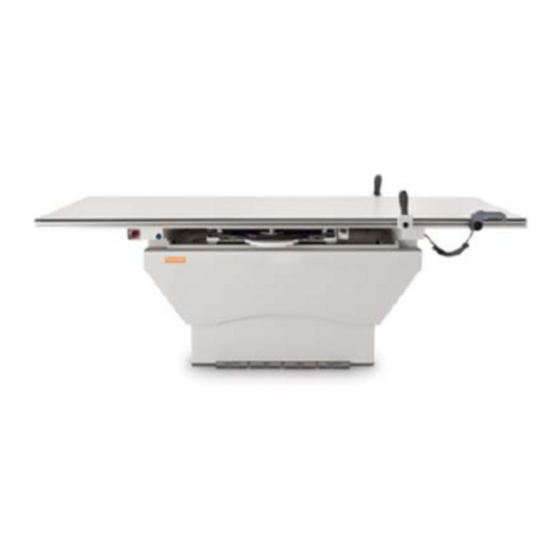
20 to 80%, non-condensing Altitude: -30.5 to +2440 meters relative to sea level NON-OPERATING ENVIRONMENT Ambient Temperature: -18°C to +70°C Relative Humidity: 20 to 95%, non-condensing Altitude: -30.5 to +3048 meters relative to sea level Models QT-740 & QT-750 - Service Manual... - Page 11 Chapter 1 Specifications Figure 1. Model QT-740 Table Configuration Diagram Models QT-740 & QT-750 - Service Manual...
- Page 12 Chapter 1 Specifications Figure 2. Model QT-750 Table Configuration Diagram Models QT-740 & QT-750 - Service Manual...
- Page 13 Chapter ASSEMBLY & INSTALLATION...
-
Page 15: Chapter 2 Assembly & Installation
Should there be a shortage or Examine all car- tons and crates damage, notify Quantum Medical Imaging, LLC.’s customer service department imme- carefully at time diately. The manufacturer is relieved of any responsibility for damage during ship- of delivery. -
Page 16: Electrical Connections
(2A for 115 VAC line input, 1A for 230 VAC line input for Model QT-740 tables; 6A for 115 VAC line input, 3A for 230 VAC line input for Model QT-750 tables). - Page 17 Chapter 2 Assembly & Installation TERMINAL BOARD TB1 TERMINAL BOARD TB2 POWER INPUT CABLE Figure 3. Connecting Input Power Cable Figure 4. System Ground Wire Connections Models QT-740 & QT-750 - Service Manual...
-
Page 18: Alignment Procedures
3. Position the collimator to approximately 24" source-to-image distance (SID). 4. Insert a 14" x 17" cassette into the film tray. 5. Turn on power to the table. Models QT-740 & QT-750 - Service Manual... - Page 19 3/8" diameter holes in the front and back (be sure the lev- eling shim plates are in the proper position). Use hardware suitable for the type of floor in the installation and of sufficient strength to handle 500 lb. pull-load. Models QT-740 & QT-750 - Service Manual...
-
Page 20: Tabletop Assembly/Installation
3. Remove two (2) Table Top End Stop Bumpers from Tabletop Frame (see Fig- ure 6). TABLE TOP ASSEMBLY END TRIM PLATE END STOP BUMPERS TABLETOP SUPPORT Figure 6. Table Top End Trim Plate and End Stop Bumpers Models QT-740 & QT-750 - Service Manual... - Page 21 (i.e., step 10a width minus step 10b width) does not exceed 1/32" as this may adversely affect tabletop motion. SOCKET HEAD CAP SCREWS (2X) SET SCREWS (2X) Figure 7. Adjusting the Tabletop Width Models QT-740 & QT-750 - Service Manual...
- Page 22 11. Install the radiographic portion of tabletop (i.e., phenolic) by carefully placing it on the Tabletop Assembly. 12. Press down firmly along all four edges of the phenolic tabletop to secure. Models QT-740 & QT-750 - Service Manual...
-
Page 23: Operational Checks And Adjustments
Table down height should be 21.5" (546.1 mm). If not, loosen two (2) screws on Down Limit Safety Switch Mounting Bracket and adjust position of the Down Limit Safety Switches. Verify correct table top height after adjustment. Models QT-740 & QT-750 - Service Manual... -
Page 24: Pedal Disable Switch Operational Check
2. Check that all foot pedal functions are disabled, and check that FLOAT push button is disabled. 3. Depress the Pedal Disable Switch until switch lamp extinguishes. 4. Check that all pedal functions and FLOAT push button are operational. Models QT-740 & QT-750 - Service Manual... -
Page 25: Checking The Obstruction Sensors (Elevating Table Only)
BEARING RAIL Figure 10. Obstruction Sensor (Typical) POSITIVE BEAM LIMITATION (PBL) COLLIMATORS For Positive Beam Limitation (PBL) Collimators and Elevating Tables only, verify the Vertical SID Interlock feature is functioning properly as follows: Models QT-740 & QT-750 - Service Manual... -
Page 26: Model Qt-750 Covers Installation/Adjustment Procedure
3. Attach the Lower Front Cover to aluminum base plate using four (4) 10-32 x 3/8" screws with external tooth star washers (see Figure 11). Do not fully tighten screws at this time. Models QT-740 & QT-750 - Service Manual... - Page 27 If adjustment is necessary, adjust lower covers in or out on slots, as required. Re-assemble upper covers and re-check for interference. When position is correct, remove upper covers and fully tighten lower cover mounting screws. Re-install upper covers and test run table to verify no interference. Models QT-740 & QT-750 - Service Manual...
- Page 28 Chapter 2 Assembly & Installation UPPER REAR COVER Figure 13. Upper Rear Cover Installed Models QT-740 & QT-750 - Service Manual...
- Page 29 Chapter THEORY OF OPERATION...
-
Page 31: Chapter 3 Theory Of Operation
Chapter 3 Theory of Operation OVERVIEW Model QT-740 and QT-750 Odyssey HF Series X-ray Generators feature a tabletop that "floats" in four directions for transverse and longitudinal patient positioning. The tabletop of Model QT-750 can also be raised and lowered. -
Page 32: Foot Pedal Disable Circuit
A1DB1 and capacitors A1C20 and A1C21 to produce 24-28 VDC unregulated voltage. The +24 VDC is monitored by comparator A1U5B; if the voltage level falls below 15% nominal, a motor drive inhibit signal is output from A1U5B-7 Models QT-740 & QT-750 - Service Manual... - Page 33 A1U6A-3, thereby resetting A1U6A and stopping tabletop vertical motion. • After 24 seconds from the time the active low /UP signal was first applied, the output at one-shot A1U6A-6 returns to a low level. (A1U6A Models QT-740 & QT-750 - Service Manual...
- Page 34 A1U1C to go low in approximately 150 milliseconds. This energizes A1K4, which removes the connection from A1J1-1 and A1J1-9, thus allowing the DC motor to rotate. The INHIBIT outputs are applied through Models QT-740 & QT-750 - Service Manual...
- Page 35 Assemblies. When the tabletop is lowered, the lead screws drive the Ball Nut Assemblies toward the Down Limit Switches. At the point where switches S7 and/or S10 are activated, a low DN LIMIT signal is applied Models QT-740 & QT-750 - Service Manual...
-
Page 36: Float Control
(i.e., at 40" SID). Relay A1K7 is energized when the table is at its maximum up position (as indicated when the /UP LIMIT signal is active low) to indicate the 40" SID position via relay Models QT-740 & QT-750 - Service Manual... -
Page 37: Receptor Cabinet Lock
A1U8-4, which causes a 1-Hz square wave output at A1U8-3. The out- put from A1U8-3 turns transistor A1Q4 on and off, generating the FLASH signal that drives the EMERGENCY SWITCH LAMP DS1 through connector A1J2-10. Models QT-740 & QT-750 - Service Manual... - Page 38 Chapter 3 Theory of Operation THIS PAGE INTENTIONALLY LEFT BLANK Models QT-740 & QT-750 - Service Manual...
- Page 39 Chapter SERVICE INSTRUCTIONS...
-
Page 41: Chapter 4 Service Instructions
When working on the Scissors Assembly, be sure the Safety Bracket is installed (see Figure 14). Verify that the equipment is properly grounded before attempting any electrical opera- tion. SAFETY BRACKET Figure 14. Safety Bracket Installed Models QT-740 & QT-750 - Service Manual... -
Page 42: Service Maintenance
Be sure to check all six (6) mounting points. 4. Lubricate two (2) Lead Screw shafts using NGLI no. 1 grease (Lubriplate MAG-1 Polymer Grease, part number L0189-098, or equivalent). Models QT-740 & QT-750 - Service Manual... - Page 43 5. Lubricate points as shown in Figures 13 and 14. Use light weight machine quality oil only! Figure 15. Lubrication Points - Table Frame Thompson Shafts 6. Turn power on to the table. Figure 16. Lubrication Points - Bucky Thompson Shafts Models QT-740 & QT-750 - Service Manual...
-
Page 44: Lubrication
Lubrication Model QT-750 tables require lubrication at the locations shown in Figures 15 and 16 at least every twelve months. Model QT-740 requires lubrica- tion at the locations shown in Figure 16 at least every twelve months. REMOVAL/REPLACEMENT PROCEDURES The following procedures provide step-by-step instructions for removal and replacement of the repairable components in the table. -
Page 45: Replacing The Sync Belt (Model Qt-750 Tables Only)
2. Remove upper and lower table covers. 3. Install Service Safety Bracket. 4. Remove four (4) hex bolts securing the DC Motor to the Table Base Plate (see Figure 17). 5. Remove Drive Belt from pulley. Models QT-740 & QT-750 - Service Manual... - Page 46 This is to ensure equal torque on both Lead Screws. 12. Install Ball Screw Mounting Block on pulley end of Lead Screw and secure to Table Base Plate using two (2) 1/4-20 socket head cap screws. Models QT-740 & QT-750 - Service Manual...
- Page 47 Adjust switch height if necessary. 15. Remove Safety Bracket. 16. Reinstall upper and lower table covers (refer to Chapter 2, Assembly and Installation). 17. Turn on power. Perform an operational test and check table travel and positions. Models QT-740 & QT-750 - Service Manual...
-
Page 48: Replacing The Dc Motor (Model Qt-750 Tables Only)
1. Raise the table to the full up position and then turn power off. 2. Remove upper and lower table covers. 3. Install Service Safety Bracket. WARNING! To prevent electrical shock hazards, make sure power is off and all capacitors are dis- charged before proceeding. Models QT-740 & QT-750 - Service Manual... - Page 49 13. If necessary, readjust MOTOR SPEED potentiometer R20 on 6- Way Table Control Board A1. (It is recommended that the travel time (fully raised to fully lowered) remain in the range of between 10-17 seconds.) Models QT-740 & QT-750 - Service Manual...
-
Page 50: Receptor Cabinet Removal/Replacement
If not, re-check measurements as described in the previous step. RECEPTOR CABINET 4.25" TABLE TOP FRAME (UPPER FRONT COVER RESTS ON FRAME) Figure 21. Correct Distance for Receptor Cabinet Installation Models QT-740 & QT-750 - Service Manual... -
Page 51: Cassette Tray Removal Procedure
Fuse, 2 Amp (115 VAC EL45-008 QT-740 Input) EL45-007 Fuse, 1 Amp (230 VAC Input) Small Magnet EL58-003 QT-740 QT-750 Bucky Locking Magnet EL58-004 QT-740 QT-750 Switch, Emergency Shut EL50-009 QT-750 Switch, Foot Pedal Disable EL50-014 QT-750 Models QT-740 & QT-750 - Service Manual... -
Page 52: Ordering Information
When ordering components or parts not listed in Table 2, a complete description of the part, including its function and location should be provided with the model number and serial number of the unit. Models QT-740 & QT-750 - Service Manual... - Page 53 Chapter 4 Service Instructions NOTE: Model QT-750 Foot Pedal is shown below; Model QT-740 Foot Pedal has only one switch. Figure 22. Replaceable Parts Location Diagram Figure 23. Replaceable Parts Location Diagram Models QT-740 & QT-750 - Service Manual...
- Page 54 Chapter 4 Service Instructions Figure 24. Replaceable Parts Location Diagram Figure 25. Replaceable Parts Location Diagram Models QT-740 & QT-750 - Service Manual...
- Page 55 Chapter 4 Service Instructions Figure 26. Replaceable Parts Location Diagram Figure 27. Replaceable Parts Location Diagram Models QT-740 & QT-750 - Service Manual...
- Page 56 Chapter 4 Service Instructions Figure 28. Replaceable Parts Location Diagram Models QT-740 & QT-750 - Service Manual...
- Page 57 Chapter 4 Service Instructions Models QT-740 & QT-750 - Service Manual...
-
Page 58: Chapter 5 Diagrams
Chapter DIAGRAMS... -
Page 60: Model Qt-750 Radiographic Table Wiring Diagram
Chapter 5 Diagrams Figure 26. Model QT-740 Radiographic Table Wiring Diagram Models QT-740 & QT-750 Service Manual... -
Page 61: 4-Way Table Control Board A1 (Ay40-017T)
Chapter 5 Diagrams Figure 27. Model QT-750 Radiographic Table Wiring Diagram Models QT-740 & QT-750 Service Manual... -
Page 62: 6-Way Table Control Board A1 (Ay40-002T)
Chapter 5 Diagrams Figure 28. 4-Way Table Control Board A1 (AY40-017T) Models QT-740 & QT-750 Service Manual... - Page 63 Chapter 5 Diagrams Figure 29. 6-Way Table Control Board A1 (AY40-002T (Sheet 1 of 2)) Models QT-740 & QT-750 Service Manual...
- Page 64 Chapter 5 Diagrams Figure 29. 6-Way Table Control Board A1 (AY40-002T (Sheet 2)) Models QT-740 & QT-750 Service Manual...
Need help?
Do you have a question about the QT-740 and is the answer not in the manual?
Questions and answers