
Related Manuals for Quantum QT-740


Summary of Contents for Quantum QT-740
- Page 1 ™ Models QT-740 and QT-750 Fixed/Elevating Float-Top Radiographic Tables Service Manual Manual Part No. DC30-007 Revision Q...
- Page 2 This manual is copyrighted and all rights are reserved. No portion of this document may be copied, photocopied, reproduced, translated, or reduced to any electronic medium or machine readable form without prior consent in writing from Quantum Medical Imaging, (QMI) Copyright©...
- Page 3 Incorporated ECO 1807, 1850, 1859, 1880 Page Page Page Number Number Number i - iv 1-1 thru 1-8 2-1 thru 2-24 3-1 thru 3-6 4-1 thru 4-34 5-1 thru 5-9 Models QT-740 & QT-750 - Service Manual Revision Q Quantum Medical Imaging...
- Page 4 Revision History THIS PAGE INTENTIONALLY LEFT BLANK Revision Q Models QT-740 & QT-750 - Service Manual Quantum Medical Imaging...
-
Page 5: Table Of Contents
Bucky Power Input Connections ..............2-6 PBL Interlock Cable Connections ..............2-6 TABLE LEVELING AND MOUNTING ................ 2-8 MODEL QT-740 - LEVELING AND MOUNTING INSTRUCTIONS ......2-8 MODEL QT-750 - LEVELING AND MOUNTING INSTRUCTIONS ......2-8 ALIGNMENT PROCEDURES ................... 2-9 IMAGE RECEPTOR/COLLIMATOR X-RAY ALIGNMENT .......... - Page 6 REPLACEMENT PARTS AND ORDERING INFORMATION ........4-24 ORDERING INFORMATION ................4-27 Chapter 5 Diagrams Model QT-740 Radiographic Table Wiring Diagram ..........5-3 Model QT-750 Radiographic Table Wiring Diagram ..........5-4 4-Way Table Control Board A1 (AY40-017T) ............5-5 6-Way Table Control Board A1 (AY40-030T) Test Point Diagram ......5-6 Table Base Plate Mounting Hole Locations ............5-7...
- Page 7 Chapter SPECIFICATIONS...
-
Page 9: Chapter 1 Specifications
Compatible With: Grid Cabinet, Bucky, ACL Bucky Receptor Longitudinal Travel: 20.0 inches (508.0 mm) **(see note 2) **Note 2: 17.00 inches (431.8 mm) of receptor travel with QT-DDS option Models QT-740 & QT-750 - Service Manual Revision Q Quantum Medical Imaging... -
Page 10: System Specifications
30 to 75%, non-condensing Atmospheric Pressure: 700 hPa to 1060 hPa NON-OPERATING ENVIRONMENT Ambient Temperature: -18°C to +70°C Relative Humidity: 20 to 95%, non-condensing Atmospheric Pressure: 500 hPa to 1060 hPa Revision Q Models QT-740 & QT-750 - Service Manual Quantum Medical Imaging... - Page 11 TO INSTALL TABLETOP (ON EITHER LEFT OR RIGHT SIDE OF TABLE) 24.04 PC.G. 15.19 PC.G. 34.00 35.5 32.50 10.79 PC.G. 26.00 Figure 1-1. Model QT-740 Table Configuration Diagram Models QT-740 & QT-750 - Service Manual Revision Q Quantum Medical Imaging...
- Page 12 NOTE: CENTER-OF-GRAVITY (C.G.) IS CALCULATED WITH TABLE FULLY ELEVATED AND WITHOUT PATIENT. 32.50 10.79 PC.G. 26.00 85.00 2.75 32.50 24.04 PC.G. 34.00 21.00 Figure 1-2. Model QT-750 Table Configuration Diagram Revision Q Models QT-740 & QT-750 - Service Manual Quantum Medical Imaging...
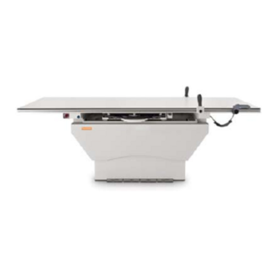
- Page 13 Chapter 1 Specifications Figure 1-3. Table with QT-DDS Option (Slide-Out Canon Digital Receptor) Models QT-740 & QT-750 - Service Manual Revision Q Quantum Medical Imaging...
- Page 14 Chapter 1 Specifications THIS PAGE INTENTIONALLY LEFT BLANK Revision Q Models QT-740 & QT-750 - Service Manual Quantum Medical Imaging...
- Page 15 Chapter ASSEMBLY & INSTALLATION...
-
Page 17: Chapter 2 Assembly & Installation
To install the tabletop, proceed to the paragraph entitled "Tabletop Assem- bly/Installation" before performing the next procedure. Models QT-740 & QT-750 - Service Manual Revision Q Quantum Medical Imaging... -
Page 18: Electrical Connections
(2A for 115 VAC line input, 1A for 230 VAC line input for Model QT-740 tables; 6A for 115 VAC line input, 3A for 230 VAC line input for Model QT-750 tables). - Page 19 TERMINAL BOARD TB2 POWER INPUT CABLE Figure 2-1. Connecting Input Power Cable 3. Connect system ground wires as shown in Figure 2-4. Figure 2-2. System Ground Wire Connections Models QT-740 & QT-750 - Service Manual Revision Q Quantum Medical Imaging...
-
Page 20: Re-Configuring Ac Line Input Transformer (115 Vac/230 Vac Input)
VAC). If it is necessary to re-configure from 115 VAC to 230 VAC, or 230 VAC to 115 VAC, make connections at terminal block TB1, located on table base, as shown in Figure 2-3 and Model QT-740 and QT-750 Radio- graphic Table Wiring Diagrams in Chapter 5, Diagrams.
Need help?
Do you have a question about the QT-740 and is the answer not in the manual?
Questions and answers