Table of Contents
Advertisement
Quick Links
Operation
®
ToughTek
Electric mixing pump for use with Ardex brand self-leveling underlayment materials. For
professional use only.
Not approved for use in explosive atmospheres or hazardous locations.
See page 2 for model information.
Maximum Working Pressure: 300 psi (
Important Safety Instructions
Read all warnings and instructions in this and all
related manuals. Save these instructions.
MP-Series Mixing Pumps
2.07 MPa, 20.7 bar)
3A4789E
EN
Advertisement
Table of Contents

Subscribe to Our Youtube Channel
Related Manuals for Graco ToughTek MP Series


Summary of Contents for Graco ToughTek MP Series
- Page 1 Operation 3A4789E ® ToughTek MP-Series Mixing Pumps Electric mixing pump for use with Ardex brand self-leveling underlayment materials. For professional use only. Not approved for use in explosive atmospheres or hazardous locations. See page 2 for model information. Maximum Working Pressure: 300 psi ( 2.07 MPa, 20.7 bar) Important Safety Instructions Read all warnings and instructions in this and all...
-
Page 2: Table Of Contents
Startup After Extended Storage ... . 19 Graco Information ......56 Routine Maintenance . -
Page 3: Warnings
Warnings Warnings The following warnings are for the setup, use, grounding, maintenance, and repair of this equipment. The exclama- tion point symbol alerts you to a general warning and the hazard symbols refer to procedure-specific risks. When these symbols appear in the body of this manual or on warning labels, refer back to these Warnings. Product-specific hazard symbols and warnings not covered in this section may appear throughout the body of this manual where applicable. - Page 4 Warnings WARNING EQUIPMENT MISUSE HAZARD Misuse can cause death or serious injury. • Do not operate the unit when fatigued or under the influence of drugs or alcohol. • Do not exceed the maximum working pressure or temperature rating of the lowest rated system component.
-
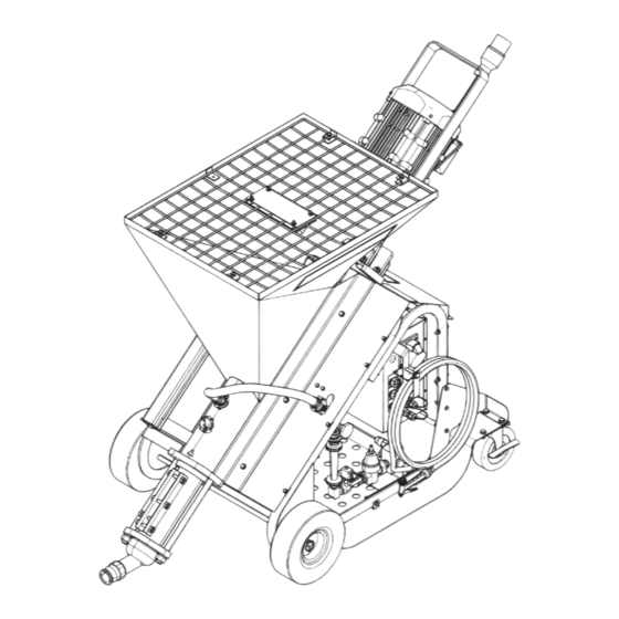
Page 5: Component Identification
Component Identification Component Identification MP-20 and MP-40 Series Ref. Description Ref. Description Motor Latch Pressure Test Hose Pump Assembly Outlet Power Cable Clean-Out Shaft Motor Cable Water Pump Drive/Mix Shaft Water Pump Inlet Gear Box Motor Water Flow Meter Rotor/Stator Pump Wash-Down Hose Control Box Water Flow Adjustment Valve... -
Page 6: Control Box
Component Identification Control Box Ref. Description Power Out Connector Main Power In Connector Water Valve Connector Water Pressure Connector Remote Switch Connector Water Pump Connector Control Box Control Panel Ref. Description Main Power Disconnect Switch Start/Stop Push Button Speed Selector Knob Forward/Reverse Pump Direction Switch Water Prime Button Water Pump Button... -
Page 7: Water Pressure Over-Ride Plug (Op)
Component Identification Water Pressure Over-ride Plug (OP) The water solenoid valve requires 40 psi of water pressure to be energized. If the water pressure is not 40 psi or greater, the solenoid valve will remain normally closed, blocking the flow of water. This operation can be overridden by unplugging the water pressure connector (DD) and connecting the water pressure override plug (OP). -
Page 8: Set Up
Set Up Set Up 3. Make sure the motor shaft adapter (MS) and drive/mix shaft (D) are aligned so the drive shaft flat slides into the motor shaft adapter slot. If they do not align, rotate them into position. NOTE: For letter references, see the Component Identification section, starting on page 5. -
Page 9: Electrical Connections
Set Up 5. Secure the hopper grate (J) onto the top of the hop- Electrical Connections per (H). Power Cable Color Code Power Cable MTA727 To help prevent injury from moving parts, do not (for systems 25M070, 25M071): operate with the grate (J) removed. Line 1 Black Line 2... -
Page 10: Operation
Operation Operation NOTE: For letter references, see the Component 2. Attach the hose to the water pump system bypass Identification section, starting on page 5. outlet (HH). Priming Hoses with Water NOTICE To prevent material curing in the hose, never load material into a dry hose. - Page 11 Operation 9. Run clean-out ball(s) to coat the inside of the hoses: b. Reattach the hose to the water pump system bypass outlet (HH), open the ball valve, and a. Remove the hose inlet from the water pump press the water pump button (Z) to resume system bypass outlet (HH) and place a hose flushing the hose.
-
Page 12: Priming System With Water
NOTE: If water does not fill the mixing chamber, see water will drain from the hoses. Startup After Extended Storage, page 19, or con- tact Graco Technical Support. 7. Perform Pump Pressure Setting procedure, page 3. Add dish soap or a slicking agent to the water through the lower port and replace the Geka fitting 8. -
Page 13: Pump Pressure Setting
Operation Pump Pressure Setting 5. Use the speed selector knob (V) to change the pump speed to level 2. 6. Slowly close the pressure test hose ball valve. 1. Attach the pressure test hose (A) to the pump outlet (L) with the pressure test hose ball valve turned to OPEN. -
Page 14: Prime And Pump Material
Operation Prime and Pump Material NOTE: Keep the hopper filled with dry material when priming with material and pumping. 4. Press the water pump button (Z) (on water pump models) and START button (U). Material should start to flow from the hose outlet (L). To help prevent injury from moving parts, do not operate with the grate (J) removed. -
Page 15: Pressure Relief Procedure
Operation Pressure Relief Procedure Follow the Pressure Relief Procedure NOTE: If the pump is stalled, do not run the pump whenever you see this symbol. for more than five seconds at a time or the motor control could encounter an overload error. After mul- tiple attempts to free the pump, allow the motor to cool for one minute. -
Page 16: System Flush
Operation System Flush c. Remove the drive/mix shaft (D) and replace with the clean-out shaft (M). NOTICE Failure to flush prior to material curing in the system will result in damage to the system and may require replacement of all system parts in contact with material. -
Page 17: Hose Flush
Operation Hose Flush c. Reattach the hose to the water pump system bypass outlet (HH), open the ball valve, and press the water pump button (Z) to resume 1. Attach hose to the water pump system bypass outlet flushing the hose. (HH). -
Page 18: Shutdown
Operation Shutdown Winterizing and Extended Storage 1. Follow System Flush (page 16) and Hose Flush (page 17). 1. Connect the power cable to the appropriate power 2. Disconnect the power supply. source and turn the main power disconnect switch (T) to ON. 3. -
Page 19: Startup After Extended Storage
Operation Startup After Extended Storage 4. Restart the water pump and observe that it starts up and operates correctly. While the pump is running, tighten the three bolts. Reassemble all disconnected hoses and close all water drain openings before startup. 5. -
Page 20: Routine Maintenance
Operation Routine Maintenance The following maintenance should be performed daily: 1. Flush the system (see Flush, page 13). 2. Perform the Pressure Relief Procedure, page 8. 3. Clean the hopper with a scrub pad. It is recom- mended that you clean the outside of the sprayer with a cloth and water. - Page 21 Operation 3A4789E...
-
Page 22: Troubleshooting
Troubleshooting Troubleshooting Problem Cause Solution The rotor/stator pump oper- Pump pressure is too low, stator Tighten stator to achieve suitable pumping ates, but output is low is too loose. pressure. Pump pressure is too high, stator Loosen stator to achieve suitable pumping is too tight. - Page 23 Troubleshooting Problem Cause Solution Erratic accelerated speed Material supply exhausted. Refill the hopper and prime pump with mate- rial. Motor is powered but nothing Pump pressure is too high, stator Loosen stator to achieve suitable pumping comes out of the hose is too tight.
- Page 24 Short-circuit at motor output: Check for possible poor insulation at constant speed the output line. Sudden increase in motor loading: Check for possible motor stall. NOTE: If the display shows any error codes not listed in this table, call Graco Technical Assistance. 3A4789E...
-
Page 25: Repair
Repair Repair Rotor/Stator Pump Repair If Replacing Only the Rotor or the Stator 1. Place the rotor/stator pump (RS) assembly in a vise. 2. Turn the rotor (27) counterclockwise with a flat bar or wrench to remove the rotor (27) from the stator (28). -
Page 26: Motor Seal Replacement
Repair Motor Seal Replacement Take special note of the groove positions of the grease Use a grease that has high water resistance and high seal (GS), in relation to the grease hole in the flange compression protections. If necessary, add grease on a plate (FP) and the grease fitting (GF). - Page 27 Repair 3A4789E...
-
Page 28: Parts
Parts Parts MP-20 and MP-40 Series Parts Apply pipe sealant to threads only on the flange side of the hopper (8). Apply grease lubricant to both ends of the inside of the stator (28). Apply pipe sealant to pipe threads. Torque to 60 +/- 5 ft-lb (81 +/- 6.7 N•m). -
Page 29: Mp-20 And Mp-40 Parts List
Parts MP-20 and MP-40 Parts List Ref. Part Description Qty. Ref. Part Description Qty. 128474 FITTING, 1.5 in. camlock m x 1.5 in. npt f MTA708 ENCLOSURE, control assy C19187 NUT, nex (for MP-20) see page 41 101015 WASHER, lock MTA709 ENCLOSURE, control assy ✿... - Page 30 Parts MP-20 and MP-40 Series Parts (continued) Apply pipe sealant to pipe threads. 3A4789E...
- Page 31 Parts MP-20 and MP-40 Parts List (continued) Ref. Part Description Qty. FRAME, assy, wheels, MP - - - - - CONTROL, water, assy - - - - - PUMP, assy, water, 60 hZ - - - - - (for MP-20 16a, MP-40 380V) see page 34 PUMP, assy, water, 50 Hz - - - - - (for MP-20 16A, MP-40 380V) see page 34...
-
Page 32: Water Control Assembly (Ref. 3)
Parts Water Control Assembly (Ref. 3) Add pipe sealant to all pipe fittings. For non-water pump models, positions of plug (9) and GHT fitting (3) are switched. 3A4789E... -
Page 33: Water Control Assembly Parts List
Parts Water Control Assembly Parts List Ref. Part Description Qty. Ref. Part Description Qty. † VALVE, water, 3/4 in. 24 VDC, 6W MTA992 MANIFOLD, water 117326 FITTING, bushing - - - - - FITTING, barb, hose, 1/4 npt, - - - - - FITTING, tee, 1/2 in. -
Page 34: Water Pump Assembly (Ref. 4)
Parts Water Pump Assembly (Ref. 4) ti30642b Add pipe sealant to all pipe fittings. 3A4789E... -
Page 35: Water Pump Assembly Parts List
Parts Water Pump Assembly Parts List Ref. Part Description Qty. † PUMP, water, 220V, 1ph, .33kW, 60Hz † PUMP, water, 220V, 1ph, .33kW, 50Hz - - - - - FITTING, nipple, 1 in. npt x 1 1/2 in. 106464 FITTING, tee, pipe, 1 in. npt MTA335 VALVE, ball, brass, 1 in. -
Page 36: Drive Shaft (Ref. 7)
Parts Drive Shaft (Ref. 7) MTA771 (for MP-20, MP-20 16A) MTA814 (for MP-40, MP-40 380V) 3A4789E... -
Page 37: Motor Assemblies (Ref. 10)
Parts Motor Assemblies (Ref. 10) MTA738 (for MP-20, MP-20 16A) Apply pipe sealant to threads. Apply grease lubricant to the shaft of the motor before assembly. Match orientation of grease port to port in frame. Add grease lubricant through grease port (5) after assembly. Parts List Ref. - Page 38 Parts MTA729 (for MP-40) Apply pipe sealant to threads. Apply grease lubricant to the shaft of the motor before assembly. Match orientation of grease port to port in frame. Add grease lubricant through grease port (5) after assembly. Ref. Part Description Qty.
- Page 39 Parts MTA736 (for MP-40 380V) Apply pipe sealant to threads. Apply grease lubricant to the shaft of the motor before assembly. Match the orientation of the grease port to the port in the flange. Add grease lubricant through the grease port after assembly. Parts List Ref.
-
Page 40: Power Cable (Ref. 56)
Parts Power Cable (Ref. 56) MTA727 (for MP-20, MP-20 16A). MTA007 (Plug Only). MTA728 (for MP-40). MTA935 (Plug Only). MTA851 (for MP-40 380V) 3A4789E... -
Page 41: Electrical Enclosure (Ref. 2) Parts
Parts Electrical Enclosure (Ref. 2) Parts MTA708 (for MP-20) MTA709 (for MP-20 16A) MTA710 (for MP-40) MTA711 (for MP-40 380V) 3A4789E... -
Page 42: Electrical Enclosure Parts List
Parts Electrical Enclosure Parts List Ref. Part Description Qty. Ref. Part Description Qty. MTA831 CONTROL, vfd keypad - - - - - ENCLOSURE, control - - - - - MODULE, din rail assembly, MTA926 FILTER, fan, assembly MP-20 (see page 47) MTA881 KIT, filter, cooling fan (pack of 5) - - - - - MODULE, din rail assembly,... -
Page 43: Wiring Schematics
Wiring Schematics Wiring Schematics MP-20 (MTA708) Motor Power Volt:0-220Vac DISC1 Amp: 25 A VFD Power CON1-1 CON2-1 R/L1 U/T1 CON1-2 CON2-2 S/L2 V/T2 CON2-3 T/L3 W/T3 CON1-GND CON2-GND TB05 24Vdc (high) : RUN 0Vdc (low) : START Speed Select SW 2 TB22-7 24Vdc (high) : Not selected 0Vdc (low) : Selected... -
Page 44: Mta709)
Wiring Schematics MP-20 16A (MTA709) Motor Power Volt:0-220Vac DISC1 Amp: 25 A VFD Power CON1-1 CON2-1 R/L1 U/T1 CON1-2 CON2-2 S/L2 V/T2 CON2-3 T/L3 W/T3 CON1-GND CON2-GND TB05 24Vdc (high) : RUN 0Vdc (low) : START Speed Select SW 2 TB22-7 24Vdc (high) : Not selected 0Vdc (low) : Selected... -
Page 45: Mta710)
Wiring Schematics MP-40 (MTA710) Amps:30 A Max Motor Power Volt:0-220Vac Amp: 25 A DISC1 VFD Power CON1-1 CON2-1 R/L1 U/T1 CON1-2 CON2-2 S/L2 V/T2 CON1-3 CON2-3 T/L3 W/T3 CON1-GND CON2-GND TB05 24Vdc (high) : RUN 0Vdc (low) : START Speed Select SW 2 TB22-7 24Vdc (high) : Not selected... -
Page 46: 380 Vac And Neutral (Mta711)
Wiring Schematics MP-40 380 Vac and Neutral (MTA711) Power In Motor Power Volts:380-415Vac Volt:0-380Vac Amps:32 A Max Amp: 18 A DISC1 VFD Power CON1-1 CON2-1 R/L1 U/T1 CON1-2 CON2-2 S/L2 V/T2 CON1-3 CON2-3 T/L3 W/T3 CON1-N CON2-GND CON1-GND TB05 24Vdc (high) : RUN 0Vdc (low) : START Speed Select SW 2... -
Page 47: Din Rail Assembly Modules
Wiring Schematics Din Rail Assembly Modules Module, din rail assembly (for MP-20) Module, din rail assembly (for MP-40) Ref. Part Description Qty. Ref. Part Description Qty. MTA886 KIT, relay, 5 pin, 24 VDC MTA886 KIT, relay, 5 pin, 24 VDC MTA884 KIT, fuse MTA884 KIT, fuse MTA889 KIT, power supply, 24 VDC, 15... -
Page 48: Systems And Accessories
Systems and Accessories Systems and Accessories Systems With Water Pump Description Power Motor Part MP-20 220V, 1-ph, 60 Hz, 30A 5.4 hp (4 kW) 25M070 MP-20 16A 220V, 1-ph, 50 Hz, 16A 5.4 hp (4 kW) 25M071 MP-40 220V, 3-ph, 60 Hz, 25A 7.5 hp (5.5 kW) 25M072 MP-40 380V 380V, 3-ph, 50 Hz, 25A... -
Page 49: Drive Shaft Kits
Systems and Accessories Drive Shaft Kits Description System Used On Kit Type MTA706 KIT, shaft, clean out, MP-20/40 MP-20 (25M070), Clean out shaft MP-20 16A (25M071), MP-40 (25M072), MP-40 380V (25M073) MTA712 KIT, shaft, drive, assembly, MP-20 MP-20 (25M070), Drive shaft MP-20 16A (25M071) MTA713 KIT, shaft, drive assembly, MP-40 MP-40 (25M072),... -
Page 50: Dimensions (For All Models)
Dimensions (for all models) Dimensions (for all models) 45.5" 53" (116 cm) (134 cm) 32.25" 64" (82 cm) (163 cm) 3A4789E... - Page 51 Dimensions (for all models) 3A4789E...
-
Page 52: Technical Specifications
Technical Specifications Technical Specifications ToughTek MP-20 Mixing Pump 25M070 Metric Maximum Fluid Working Pressure 300 psi 2.07 MPa, 20.7 bar Maximum Motor Speed 314 rpm Weight (empty) 430 lb 195 kg Hopper Capacity 37.4 gallons 141.6 liters Wetted Parts ® Tool steel, painted steel, plated steel, PORON Fluid Inlet Size 3.0 in. - Page 53 Technical Specifications ToughTek MP-20 16A Mixing Pump 25M071 Metric Maximum Fluid Working Pressure 300 psi 2.07 MPa, 20.7 bar Maximum Motor Speed 244 rpm Weight (empty) 430 lb 195 kg Hopper Capacity 37.4 gallons 141.6 liters Wetted Parts ® Tool steel, painted steel, plated steel, PORON Fluid Inlet Size 3.0 in.
- Page 54 Technical Specifications ToughTek MP-40 Pump 25M072 Metric Maximum Fluid Working Pressure 300 psi 2.07 MPa, 20.7 bar Maximum Motor Speed 327 rpm Weight (empty) 480 lb 218 kg Hopper Capacity 37.4 gallons 141.6 liters Wetted Parts ® Tool steel, painted steel, plated steel, PORON Fluid Inlet Size 3.8 in.
- Page 55 Technical Specifications ToughTek MP-40 380V Mixing Pump 25M073 Metric Maximum Fluid Working Pressure 300 psi 2.07 MPa, 20.7 bar Maximum Motor Speed 349 rpm Weight (empty) 450 lb 204 kg Hopper Capacity 37.4 gallons 141.6 liters Wetted Parts ® Tool steel, painted steel, plated steel, PORON Fluid Inlet Size 3.8 in.
-
Page 56: Graco Standard Warranty
With the exception of any special, extended, or limited warranty published by Graco, Graco will, for a period of twelve months from the date of sale, repair or replace any part of the equipment determined by Graco to be defective.
Need help?
Do you have a question about the ToughTek MP Series and is the answer not in the manual?
Questions and answers