Table of Contents
Advertisement
Quick Links
Advertisement
Table of Contents

Related Manuals for horsch SW 3500 S


Summary of Contents for horsch SW 3500 S
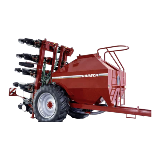
- Page 1 Specialists in modern cultivation and seeding technology 04/2007 HORSCH Säwagen HORSCH Säwagen SW 3500 S / 7000 S SW 3500 S / 7000 S Operating Instructions Read carefully prior to starting up! Keep operating instructions in a safe place! Art.: 80730200 en...
- Page 2 EC Declaration of Conformity In accordance with EC Directive 98/37/EC HORSCH Maschinen GmbH Sitzenhof 1 D-92421 Schwandorf do solely declare that the product HORSCH Säwagen 3500 S Säwagen 7000 S which is the subject of this declaration, fully conforms with the pertinent safety and health require- ments specified in EC Directive 98/37/EC.
- Page 3 I hereby confirm receipt of the operating instructions and spare parts list for the above mentioned machine. I have been instructed by a HORSCH service technician or authorised dealer in the operation and functions of the machine, as well as in the safety requirements.
- Page 5 Publication date of Operation Manual: 04/2007 Address of Retailer: Name: ..............Road: ..............Town/City: ..............Tel.: ..............Customer No.: Retailer: ..............Address of HORSCH: HORSCH, LLC 200 Knutson St. Mapleton, ND 58059 USA +701-532-1000 Tel.: Fax: +701-532-1101 E-mail: info.us@horsch.com Customer No.: HORSCH: ..............
-
Page 6: Table Of Contents
Optional equipment ........42 SW 3500 S ..........17 Solid fertiliser facility ........42 Technical data ..........17 Adjusting the fan air flow ......42 Hydraulic system SW 3500 S Filling auger ..........43 with Maistro 8 and 9 RC ......18 Brake systems ..........44 Hydraulic function ........19 Service and maintenance ......46... -
Page 8: Introduction
Exchange parts, which require the old part to be returned, are marked with the letter "R". HORSCH will not assume liability for any dam- Please clean and empty such parts and return age or malfunctions resulting from failure to them within 4 weeks, along with a claim form and comply with the operating instructions. -
Page 9: Intended Use
Genuine spare parts and accessories from incorrect drive motor speeds and driving HORSCH have been specially designed for this speeds. machine. Spare parts and accessories which incorrect setting of the unit (incorrect connec- ... -
Page 10: Authorised Operators
Authorised operators In these operating instructions Only those persons who have been authorised The operating instructions distinguish between and instructed by the operator may operate the three different types of warning and safety in- machine. Operators must be at least 16 years structions. -
Page 11: Information Regarding Safety
Information regarding When hitching up the drill and when operating the hydraulic safety system, no persons should be between the machines. The following warnings and safety instructions apply to all sections in these operating instruc- tions. Safety symbols On the machine Read and adhere to the operat- No passengers are allowed to ing instructions before starting... - Page 12 Never reach with your hands in Stay clear of swinging area the rotating auger. of retractable and extendible machine parts! It is only permitted to remain Do not climb on rotating parts. in the danger zone when the Use mounting steps provided lifting cylinder safety device is for this purpose.
- Page 13 Caution! Danger of tipping over. Always lower the drill to the ground before unhitching. The seed wagon could otherwise fold up. 0 0 3 8 0 3 1 7 Lever position for hydraulic upper link, locked in transportation and working position. Only open for depth setting and when changing from transportation to working position.
- Page 14 The permissible fan speed must not be ex- ceeded and preload the wing hydraulics with 100 to 120 bar. m ax: 4500 1/m in P= m in 100 + 20 bar m ax: 4000 1/m in 00380498 The return flow pressure at the fan drive must not exceed 5 bar, as otherwise the hydraulic motor may be destroyed.
- Page 15 Attach the scales here when calibrating. O FF ZERO 00380879 Retighten the wheel nuts / wheel bolts after 50 hours. 50 h / Nm 00380359 Maschine Zeichnung Zeichnungsnummer Dateiname alle Waage 00380879 Lifting hook; attach lifting tackle (chains, ropes, etc.) here when performing loading work. 00380880 Maschine Zeichnung...
- Page 16 00110683 00110684 Hydraulic valve block Machine up / down 00110682 00110687 00110685 00110686 Maschine Zeichnung Zeichnungsnummer Dateiname Aufkleber 00110681 - 7 Unfold / fold machine 00110681 00110682 00110687 00110684 00110681 00110682 00110687 Bout marker 00110682 00110687 00110682 00110687 00110683 00110684 00110682 00110687 00110686...
-
Page 17: Operational Safety
In addition to the operating instructions, it is after receiving instructions by employees of the important to observe the accident prevention authorized dealer or a HORSCH employee. The regulations specified by agricultural trade as- machine registration form has to be completed sociations! and returned to HORSCH. -
Page 18: Changing Implements
Service and maintenance The control units on the tractor must be secured or locked when not in use Ensure that regular tests and inspections are or when the machine is in transport always carried out to schedule, as specified position, in order to prevent accidents in the operating instructions. -
Page 19: Transport/Installation
Transport/Installation Installation Our customer service employees or distribu- There is increased risk of accident on initial tion partners are responsible for instructing the installation. Please pay attention to the instruc- operator and carrying out the initial installation tions in the appropriate chapters. of the machine. -
Page 20: Install Drillmanager
Install DrillManager Assembly: The basic equipment has to be installed on the tractor during initial installation in all machines with seeder controls. The cables for the basic equipment have to be directly connected to the battery on the tractor. The cables should not rub and the insulation should not be damaged. -
Page 21: Technical Data
SW 3500 S Pressure accumulator Seed wagons with pre-tools are equipped a pressure accumulator in the hydraulic system. Technical data Pressure accumulators require special caution in order to avoid accidents. Width: ...........2.95 m Transport height: ........3.35 m Do not open or work (welding, drilling) Length:..........6.85 m... -
Page 22: Hydraulic System Sw 3500 S With Maistro 8 And 9 Rc
Hydraulic system SW 3500 S with Maistro 8 and 9 RC Hydraulic system SW 3500 S with Maistro 8 and 9 RC Hydr. control unit Hydr. coupling Hydr. shut-off valve Hydr. cylinder for tools (option) Hydr. control valve block Hydr. shut-off valve for bout markers Hydr. -
Page 23: Hydraulic Function
Hydraulic function Unfold / fold machine Tractor mounted control units must be Folding: secured or locked when not in use or Connect the DrillManager Müller and select in transport position. hydraulics "Lift" in the display. Lift the machine. Persons must not remain in the op- Switch on the hydraulic "Wing"... - Page 24 Unfolding: Adjusting the wing cylinder on the seed Switch on the DrillManager Müller and raise wagon: the machine. Both wing frames are limited by stop screws on With optional equipment: Unlock the safety the frame when unfolded. catch. Mind the lock. This must drop down, In raised position both folding wings are slightly to prevent relocking.
-
Page 25: Hitching Up The Seed Wagon
Hitching up the seed wagon Connecting the hydraulic system Connect the hydraulic system only after it has been depressurized on machine and implement Nobody is to remain between the tractor side. and the machine when hitching up. The hydraulic system is under high pressure. Hydraulic oil escaping under pressure can There is a danger of being injured on function- penetrate the skin and cause serious injuries. -
Page 26: Hitching Up And Adjusting The Maistro
Then lower the depth guide wheels and lock with the bolt. If necessary match the setting to the Tractor link arm on SW 3500 S prevailing conditions and correct the height. To set the depth lower the machine in the field, until the bores for the bolt (1) are in line. -
Page 27: Parking The Machine
Parking the machine Assembly note for the bolt (1) The bolt is secured with detent edged rings on The drill should be parked in a shed or under a both sides. roof so that no moisture can accumulate in the, The individual rings are provided with fine and metering unit and seed pipes. -
Page 28: Technical Data
SW 7000 S Pressure accumulator Seed wagons with pre-tools are equipped a pressure accumulator in the hydraulic system. Technical data Pressure accumulators require special caution in order to avoid accidents. Width: ...........2.80 m Transport height: ........3.40 m Do not open or work (welding, drilling) Length:..........6.45 m on the pressure accumulator. -
Page 29: Hydraulic System Sw 7000 S With Maistro 11 Rc
Hydraulic system SW 7000 S with Maistro 11 RC Hydraulic system SW 7000 S with Maistro 11 RC Pressure gauge "Fan drive" Hydr. control unit Hydr. motor "Fan drive" Hydr. coupling Hydr. control valve block Hydr. check valve Hydr. shut-off valve Two-way valve Hydr. -
Page 30: Hitching Up And Adjusting The Maistro
Hitching up and adjusting the Hitching up and adjusting the Maistro Focus The Maistro 11 RC is hitched up by the 3-point The Focus CS is hitched up by the 3-point hitch hitch at the rear of the seed wagon. at the rear of the seed wagon. -
Page 31: Parking The Machine
Parking the machine The drill should be parked in a shed or under a roof so that no moisture can accumulate in the, metering unit and seed pipes. When manoeuvring the machine, pay attention to the surroundings. No persons (children) are to remain in the manoeuvring area of the machine. -
Page 32: Hopper
Hopper Venturi-type injector On the SW 3500 S the hopper is an "open hop- In the Venturi-type injector the metering unit in- per", whereas on the SW 7000 S it is a "pres- jects the seed or the fertiliser into the air flow. -
Page 33: Fan
Fan impeller and protection grille must be checked regularly for dirt deposits and cleaned The hydraulic fan is directly driven by the tractor accordingly. hydraulics or by a PTO-shaft driven pump. Deposits on the protection grille restrict the The generated air flow conveys seed of ferti- air flow and thus lead to blockage in the seed liser from the Venturi area to the coulters. - Page 34 Direct drive fan motor The return line connected to the tractor must enable free return flow! Leak oil return flow pressure max. 5 bar! Rotary speed max. 4000 - 4500 rpm Fan motor Fan drive hydraulics Hydr. valve with flow control Hydr.
-
Page 35: Fan With Power Take-Off Pump
Fan with power take-off pump Function The power take-off pump powers the hydr. mo- The hydraulic fan is powered by a power take- tor of the fan. off pump. A pressure gauge displays the operating pres- sure on the hydraulic system. This increases proportionately with the fan speed and should read between 50 and 130 bar. - Page 36 Adjusting fan performance Checks and Maintenance The flow rate of the fan depends on the power Observe return pressure of max. 2 bar. take-off speed. Check oil level. The fan speed can be reduced on the excess air Clean protective guard for fan and cooler ...
- Page 37 Fan with power take-off pump Malfunction Possible cause Remedy Bearing damage on fan Normal wear Replace bearing Fan run on excess power Never operate fan without pneumatic tubes Unbalance on wheel Replace wheel or clean in case of dirt Shaft sealing ring on motor untight Return pressure larger than 2 bar Check return pressure Hydr.
-
Page 38: Re-Tightening The Fan Impeller
Re-tightening the fan impeller The imperial screws in the version no. 10 - 24 4.6 must be tightened to a max. torque The conical clamp on the hydraulic motor fan of 6.8 Nm. drive can become loose due to temperature After tightening, check the impeller for free ... -
Page 39: Metering Unit
Metering unit Different metering rollers are available for sow- ing different grain sizes and seed quantities. The The HORSCH metering unit comprises of only a rollers are selected according to the table in the few individual components and can be disman- section entitled “calibration test”. -
Page 40: Roller Replacement
The base of the metering unit is shut off from the Venturi pipe. In the Venturi pipe, the seed is transported by the stream of air. When calibrating, the seed is removed from the metering unit via the opening in the Venturi pipe. -
Page 41: Checking Rubber Sealing Strip
Checking rubber sealing strip Roller for sowing small seed A defective sealing strip or incorrectly The rollers for sowing small seeds comprise fitted support plate will lead to metering metering discs, spacers and drive shaft. errors when sowing. In order to prevent problems when sowing small The sealing strip must not be torn or damaged, seed, the metering rollers are completely pre- ... - Page 42 When fitting or removing the rollers, the stops Then fit the circlip. must be turned so that they are in line with the If the roller has been assembled correctly, the slot in the housing. metering wheels between the spacers can just be turned freely.
-
Page 43: Rape Brushes
Rape brushes Large seed The rape brushes clean the metering discs in In the case of large seed (maize, beans, peas, the roller for sowing small seeds. etc.), a deflector is installed instead of the rape brushes. Prior to sowing small seed, the rape brushes This deflector prevents large seeds from becom- must be installed in the rear cover and tested ing jammed and ground up between the roller... -
Page 44: Venturi-Type Injector
Venturi-type injector In extreme cases, the vacuum can block the flow of seed in the tank and cause the seed being The metering units in machines with standard metered to stop. tank and Venturi-type injector are equipped with a V2A cover with recesses. Therefore, always check that the pneumatic system is functioning prop- When in operation, a vacuum is created in the... -
Page 45: Metering Unit Maintenance
Metering unit maintenance The metering unit requires no special mainte- nance. To avoid repair-related downtimes, the meter- ing unit and drive motor should be cleaned at the end of the season and checked for correct function. In particular, the bearings in the side cover and on the drive motor can be damaged and/or be- come sluggish as a result of dressing dust. -
Page 46: Optional Equipment
Optional equipment Depth setting The desired depth setting for the fertiliser place- ment must be adapted to the soil conditions in Solid fertiliser facility the field. With the solid fertiliser facility solid fertiliser can The depth of the fertiliser shares is set by the be placed simultaneously by the towed machine adjustable bolt on the hydraulic cylinder. -
Page 47: Filling Auger
Filling auger Operation Do not reach with your hand into the The filling device consists of a fixed and a move- rotating auger! able auger half. Always lock the eccentric interlock! For road travel the auger must be It enables simple and quick filling of the seed folded in and locked in place. -
Page 48: Brake Systems
Brake systems In case of a pressure loss the braking effect of the parked machine will The seed wagon can be equipped with a pneu- drop. matic brake system. The machine must therefore be parked in such This is a dual-line single-circuit brake with pres- a way, that it cannot roll away, even without sure regulator. - Page 49 Adjusting the brake power controller The brake power controller reduces the applied brake pressure according to the setting of the control valve. This setting must be manually adapted to the load condition. The adjustment lever can be set either to "No load", "Partial load"...
-
Page 50: Service And Maintenance
Service and maintenance Maintenance intervals The maintenance intervals are determined by many different factors. Follow the safety instructions regarding For instance, not only do the different operating service and maintenance. conditions, climatic conditions, driving and op- erating speeds, dust and type of soil, the seed, Your machine has been designed and assem- fertiliser and dressing used, etc., have an effect bled for maximum performance, economy and... -
Page 51: Lubricating The Machine
Service Lubricating the machine The machine should be lubricated regularly and We at HORSCH want you to be completely satis- each time it is washed with high pressure. fied with your machine and with us. This ensures readiness for use and reduces repair costs and downtimes. -
Page 52: Maintenance Overview
Maintenance Overview Maintenance schedule SW 3500 S / 7000 S After the first few operating hours Work instructions Interval All screwed and plug-in connections Check for tightness and tighten screw connections in operation Check for leaks, function, speed setting operation... - Page 53 Overview of lubrication points SW 3500 S Lubrication points Number of Interval Drawbar on two-point swivel joint daily Lift shaft daily Additional Equipment Solid fertiliser facility 50 hours Wing frame bolts 50 hours Wing cylinder bolts 50 hours Filling auger...
-
Page 54: Lubrication Points
Lubrication points Lift shaft Pivot and tumbler bearings for drawbar Wing cylinder and wing frame on seed wagon Brake shaft Filling auger (Illustration similar) Brake shaft and tractor link arm SW 7000 S... -
Page 55: Bolt Tightening Torques - Metric Bolts
Bolt tightening torques - metric bolts Bolt tightening torques - metric bolts in Nm Size Pitch Type of bolt - property classes Wheel nuts/ ø mm Wheel bolts 10.9 12.9 0.50 0.70 0.80 10.4 1.00 10.4 15.3 17.9 1.00 11.5 17.2 1.25 13.6... -
Page 56: Bolt Tightening Torques - Imperial Bolts
Bolt tightening torques - imperial bolts Bolt tightening torques - imperial bolts in Nm Bolt diameter Strength 2 Strength 5 Strength 8 No marking on head 3 markings on head 6 markings on head Inch Coarse thread Fine thread Coarse thread Fine thread Coarse thread Fine thread... - Page 57 Notes:...
- Page 58 PN 05951422 Ver. 1.0 04/2007 All details on technical specifications and pictograms are approximate and for information only. Subject to technical product revisions. HORSCH, LLC Tel.: 701-532-1000 200 Knutson St. Fax: 701-532-1101 Mapleton, ND 58059 USA E-Mail: info.us@horsch.com www.horsch.com...
Need help?
Do you have a question about the SW 3500 S and is the answer not in the manual?
Questions and answers