
Subscribe to Our Youtube Channel
Related Manuals for horsch SW 12000 SD


Summary of Contents for horsch SW 12000 SD
- Page 1 OPERATING INSTRUCTIONS SW 12000 / 12003 SD TRANSLATION OF THE ORIGINAL OPERATING INSTRUCTIONS READ CAREFULLY PRIOR TO STARTING UP! KEEP OPERATING INSTRUCTIONS IN A SAFE PLACE! ART.: 60007340 ISSUE: 10/2019...
- Page 3 HORSCH: ..............Confirmation of receipt of machinery Warranty claims become only effective when the first use of the machine is reported to HORSCH Maschinen GmbH within a week. www.horsch.com under SERVICE PARTNERBEREICH an interactive PDF form is available for down- load for this purpose (not available in all languages).
- Page 4 HORSCH Maschinen GmbH Sitzenhof 1, D-92421 Schwandorf erklärt hiermit in alleiniger Verantwortung als Hersteller, dass das nachfolgend genannte Produkt: Säwagen Typ: SW 12000 SD SW 12003 SD den einschlägigen grundlegenden Sicherheits- und Gesundheitsanforderungen der Richtlinie 2006/42/EG entspricht. Schwandorf, 01.10.2019 Klaus Winkler Dokumentationsbevollmächtigter...
-
Page 6: Table Of Contents
Pneumatic system ........52 Fan ...............52 Delivery............24 Checks and maintenance ......52 Transport ............24 Technical data of fan ........53 Installation ............24 Pneumatic system SW 12000 SD ....54 Construction ..........25 Half-width shut-off ........56 Overview............25 Joining of hoppers ........57 Hydraulics .............26 Fan speeds ..........58 Marking of hydraulic hoses ......29... - Page 7 Hydraulic brake ..........77 Wheels and tyres ........101 Changing wheels (undercarriage) ....101 Protective devices ........103 Care and Maintenance ......104 Cleaning .............104 Lubricating the machine ......104 Maintenance intervals.........105 Storage ............105 Maintenance overview ........84 Lubrication points – SW 12000 SD....88 Waste disposal ...........89 Index ............90...
-
Page 8: Introduction
DANGER to the safety notes! Highlights a danger that will lead to death or HORSCH will not assume liability for any severe injury if it is not avoided. damage or malfunctions resulting from failure of complying with the operating instructions. -
Page 9: Service
Service Consequential damage The machine has been manufactured by HORSCH Company would like you to be com- HORSCH with greatest care. However, despite pletely satisfied with your machine and our the intended use deviations in placing quantity services. up to total failure may be caused by e.g.:... -
Page 10: Safety And Responsibility
The following warnings and safety notes apply is not secured against restarting to all sections in these operating instructions. HORSCH does not assume any liability for The machine has been built in accordance with damages resulting from the unintended use of latest technical standards and generally ac- the machine. -
Page 11: Qualification Of Personnel
The person has understood the operating ¾ sponding personnel must have been trained by instructions and is able to implement the in- service personnel from HORSCH. This refers to formation given in the operating instructions the following activities: accordingly. Loading and transport •... -
Page 12: Personal Protective Outfit
Personal protective outfit For machines without brake select the weight ¾ of the tractor and the speed so that the ma- chine can be managed securely under all Missing or incomplete protective equipment conditions. Remember the extended breaking increases the risk of health damage. Personal distance. -
Page 13: Safety In Operation
¾ (e.g. remove coarse dirt and tighten loose after receiving instructions by employees of screws). the authorized dealer or a HORSCH em- Have damage that could affect safety and ployee. ¾ that cannot be rectified by you rectified by a The machine registration form must be com- ¾... - Page 14 ¾ years, see Maintenance overview. unhitching. Adjustments and repair work on the brake sys- tem must only be carried out in a professional workshop or by an operator, who has been specially trained by HORSCH for this purpose.
- Page 15 Overhead lines Technical limiting values When unfolding or folding in the wings, the ma- If the technical limiting values of the machine are chine may reach the height of overhead lines. not observed, the machine may get damaged. Possible voltage flashover to the machine may This can lead to accidents with severe or even cause fatal electric shock or fire.
-
Page 16: Fertiliser And Dressed Seed
Caution! Danger of injury caused by projecting HORSCH is not liable for damages to life and ¾ parts (e.g. coulters)! limb as well as property damages resulting from unapproved retrofitting and conversions. -
Page 17: Care And Maintenance
Before starting maintenance and service work HORSCH for this purpose. ¾ park the machine on level and firm ground and secure it against rolling away. -
Page 18: Danger Zone
Danger zone Failing to pay attention to the danger zone can The area marked red indicates the danger zone result in severe or even fatal physical injuries. of the machine: Do not stand under lifted loads. Lower such ¾ loads to the ground first. Instruct persons to leave the danger zone ¾... -
Page 19: Safety Stickers
Safety stickers Safety stickers on the machine warn of hazards Clean soiled safety stickers. ¾ at dangerous points and are an important part Damaged or illegible safety stickers must be ¾ of the safety equipment of the machine. Miss- replaced immediately. ing safety stickers increase the risk of severe or Affix the specified safety stickers on spare ¾... - Page 20 Position of safety stickers (depending on equipment) Safety stickers with the addition “2x” can be found on either side of the machine.
-
Page 21: Technical Data
Technical data SW 12000 SD Variant SW Variant NT Length (m) 7.22 6.88 Transport width with tyres 650/65 R38 (m) 3.00 3.00 Transport width with tyres 900/60 R32 3.35 Transport width with tyres 4 x 20.8 R42 4.28 Height with filling auger (m) 3.93... -
Page 22: Type Plate
3000 7220 SW 12000 SD - variant SW 6880 3550 SW 12000 SD – variant NT Type plate The type plate with the CE marking is located on the frame of the machine. Data on the type plate: Vehicle class... - Page 23 SW 12003 SD Variant NT Length (m) 7.15 Transport width with tyres 650/65 R38 (m) Transport width with tyres 900/60 R32 4.08 Transport width with tyres 4 x 520/85 R 42 Height with filling auger (m) 3.83 Height without filling auger (m) 3.32 Filling height (m) 3.41...
-
Page 24: Requirements For The Tractor
Requirements for the tractor WARNING Risk of accident! Comply with the permissible values of the ¾ tractor for axle loads, total weight, ballasting, tyre load bearing capacity and air pressure. Verify the suitability of the tractor before com- ¾ missioning. The tractor must meet the following require- ments to be able to use the machine as intended: Implement attachment... - Page 25 Brake connections Pneumatic brake Red connection for supply line Yellow connection for brake line Hydraulic brake Connection acc. ISO 5676...
-
Page 26: Calculating The Ballasting
Calculating the ballasting Required data: The permissible total weight, the permissible axle loads and the load bearing capacity of the tyres must not be exceeded when mounting or hitching up implements. The front axle of the tractor must always be loaded with at least 20 % of the curb weight of the tractor. - Page 27 1. Calculation of minimum front ballasting 4. Calculation of the actual total weight with rear implement: • (c + d) - T • b + 0.2 • T • b Enter the result of the calculated total weight and a + b V min the permissible total weight from the operating instructions of the tractor into the table.
-
Page 28: Commissioning
These work activities may be carried out only by The permissible dimensions and weights for ¾ persons trained by HORSCH for this purpose. transport must be complied with. The tractor must be large enough so that ¾... -
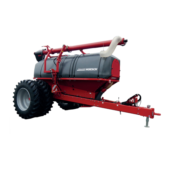
Page 29: Construction
Construction Overview SW 12003 SD – variant NT 6 Hose bracket 1 Undercarriage 7 Hitching 2 Triple hopper 8 Support 3 Platform 9 Liquid fertiliser system (option) 4 Access ladder 5 Fan for fertiliser/seed WARNING Danger of injury Do not look into the near-area of the radar ¾... -
Page 30: Hydraulics
Hydraulics WARNING Unintentional hydraulic movements may lead to severe accidents and injuries! Secure or lock the control units on the tractor. ¾ Instruct persons to leave the slewing range of ¾ foldable machine parts. Switch all control units to the locked position ¾... - Page 31 Hydraulics for Pronto NT/SW – The arrow indicates the direction of travel Hydraulic connections on rear end of seed wagon Hydraulic connection for fan Hydraulic connection for tools Hydraulic connection for folding Hydraulic connection for hydraulic valve block Hydraulic connection for folding in bout marker markers Hydraulic connection for lift/lower Hydraulic connection for unfolding bout markers Hydraulic connection for pressure gauge...
- Page 32 Hydraulics for Sprinter NT – The arrow indicates the direction of travel Hydraulic connection for folding Hydraulic connection for lift/lower Hydraulic connection for pressure gauge Hydraulic connection three-way valve for fan/filling auger Hydraulics for Sprinter NT – The arrow indicates the direction of travel...
-
Page 33: Marking Of Hydraulic Hoses
Marking of hydraulic hoses Working depth Symbols on the handles of the hydraulic cou- plings indicate the function of the respective hoses: NOTE The following hydraulic movements are carried out via the hoses marked with Lift • Lift / lower Folding in •... -
Page 34: Aluminium Clips
Aluminium clips CAUTION The aluminium clips are placed on the piston Danger of damage to the packer frame. rods of hydraulic cylinders, depending on the Depending on the design, do not remove any operating states, see chapter Operation. ¾ fixed clips or depth limitations! NOTE Pay attention to the ratio on the machine, see ¾... -
Page 35: Lighting
Lighting 7-pin plug Rear light, right Lamp, blinker Lamp, taillight Lamp, brake light Rear light, left Lamp, brake light Lamp, taillight Lamp, blinker Plugs and cable assignment No. Desig. Colour Function yellow Blinker left 54 g white Earth green Blinker right 58 R brown Rear light, right... -
Page 36: Instruction Stickers
Pressure display for fan drive Maschine Zeichnung Zeichnungsnummer Dateiname Entw. JJKW sw 12000 sd 00384071 1127 Changeover fan drive / filling auger Attach the scales here when calibrating. 00380882 Retighten the wheel nuts / wheel bolts after 50 km or 10 hours. Retighten every day - see maintenance overview. - Page 37 00385757 During drilling the pressure in the hydraulics for coulter pressure must be min. 100 bar. Lashing points; Hook fastening gear (lashing belts, chains, etc.) here. Loading work only by operators trained by HORSCH! 00385757 60010418...
-
Page 38: Operation
Operation Commissioning / Tractor change Whenever working on the machine During initial commissioning and when changing pay attention to the associated safety the tractor, the machine must be adapted to the notes in the chapter “Safety and tractor. prevention of accidents” as well as the accident prevention instructions! WARNING Dropping or lowering machine parts can cause... -
Page 39: Connecting/Parking
Loosen the screws (C) to be able to match the ¾ NOTE height of pulling lug or ball head. After adjusting the correct height fasten ¾ Check all plug-and-socket connections ¾ screws C again. (hydraulic, electric and pneumatic) for Connecting/Parking cleanliness and firm seating. -
Page 40: Hitching Up The Sw-Version
Hitching up the SW-version Transport position When connecting a Sprinter/Pronto SW, a ball- and-socket coupling or a swinging drawbar WARNING hitching is mounted on the rear end of the seed Danger of road accidents caused by losing the wagon. machine or machine parts. On the ball head coupling the hold-down must Before driving off be correctly adjusted in order to reduce the... - Page 41 Position of the control units during road travel (Pronto SW) Floating position Locked position Supply Position Control unit Hydraulic valve block Front packer Position of the control units during road travel (Pronto NT) Floating position Locked position Supply Position Control unit Hydraulic valve block Position of the control units during road travel (Sprinter HD) Floating position...
- Page 42 Position of the control units during road travel (Sprinter 11/15 NT) Floating position Locked position Supply Position Control unit Unfolding / Folding in Lift / Lower Position of the control units during road travel (Sprinter 12/18 NT) Position Floating position Locked position Supply Control unit...
-
Page 43: Parking
Parking If solid fertiliser has been placed, hopper and machine must be thoroughly cleaned. Fertiliser DANGER is aggressive and speeds up the corrosion Serious accidents from loss of stability! process. It especially attacks galvanised Park the machine only on a flat, paved sur- ¾... -
Page 44: Adjustment And Operation
Adjustment Opening/closing the hopper and operation Depending on the model and optional equipment, some assembly groups may be of different design. Seed and fertiliser hopper The seed wagons are equipped with two or three hoppers. With twin hoppers, the front and rear Opening the hopper hopper have the same size. -
Page 45: Emptying Residues
Clean the pipes from residues to avoid mis- ¾ takes during the next calibration. Fall sluice double pipe SW 12000 SD The cover must be tightly closed during sowing. Calibration For calibration open the covering under the fall sluice and hook in the calibration bag. - Page 46 Position of the control units during field use (Pronto SW) Floating position Locked position Supply Position Control unit Hydraulic valve block Front packer Position of the control units during field use (Pronto NT) Floating position Locked position Supply Position Control unit Hydraulic valve block Position of the control units during field use (Sprinter HD) Position...
- Page 47 Position of the control units during field use (Sprinter 11/15 NT) Floating position Locked position Supply Position Control unit Unfolding / Folding in Lift / Lower Position of the control units during field use (Sprinter 12/18 NT) Position Floating position Locked position Supply Control unit...
-
Page 48: Checks
Checks Pneumatic system Are the motor flaps installed in the correct ¾ seed lines for the tramlines? Has the tram line rhythm been adjusted and do the flaps close? Do the seed hoses not sag and are they free ¾ of water and deposits? Are all air lines between fan and coulters leak ¾... -
Page 49: Metering Unit
Metering unit Rotors The HORSCH metering unit consists of only A large number of rotors is available for the dif- a few individual parts and can be dismantled ferent seed types with numerous geometrical without tools. shapes and grain sizes, as well as fertilisers in form of powders or granulates. -
Page 50: Rotor Change
Rotor change Rotor change with full hopper After choosing a rotor from the table it must be installed in the metering unit. Empty the seed hopper, if possible, before ¾ changing the rotor. Unscrew the side cover. ¾ Pull out the rotor with the drive shaft. ¾... -
Page 51: Adjusting The Sealing Lip
Adjusting the sealing lip Rotors for fine seeds NOTE The rotors for fine seeds consist of cell discs, spacers and drive shaft. A defective sealing lip or incorrectly assembled supporting plate cause metering errors during In order to avoid malfunction when sowing fine sowing. - Page 52 Function test Maintenance The function and operability of fine seed rotors After installing a new rotor its function and con- must be checked every day. centricity must be checked. There should be no gap between the cell For this purpose switch on the rotor as described ¾...
-
Page 53: Rape Brushes
Urheberschutz: Für diese technische Unterlage DIN 6784 behalten wir uns alle Rechte vor. 17.04.2012 Haselhoff Adapter Bohnen für Dosiergerät PP © Horsch Maschinen GmbH © Horsch Maschinen GmbH Änderungen sind untersagt Änderungen sind untersagt 01508300 6,115 kg Bemaßungen in mm... - Page 54 Metering unit with injector fall When using the adapter frame you must install ¾ and adjust a wider sealing lip - see adjusting sluice the sealing lip. The metering units in machines with normal hopper and injector fall sluice are equipped with The special rotors for coarse seeds should be ¾...
-
Page 55: Maintenance Of Metering Unit
Maintenance of metering unit The metering unit does not require any special maintenance. In order to avoid repair related downtimes, both the metering unit and the drive motor should be cleaned and subjected to a function test after the end of the season. The bearings in the side cover in particular can be damaged or may become hard-moving be- cause of dressing dust. -
Page 56: Pneumatic System
Pneumatic system The fan speed is adjusted via the oil quantity on the flow control valve in the tractor. The hydraulic pump must deliver sufficient oil The pneumatic system consists of one or two to prevent the fan speed from dropping, even optional fans, the solids pressure hoppers, the when the tractor speed drops or other hydraulic metering units and pneumatic hose assembly. -
Page 57: Technical Data Of Fan
Technical data of fan Displacement 6" design 10 cm Displacement 8" design 19 cm Operating pressure 60 - 180 bar Fan speed up to 5,000 rpm Pressureless leak oil line required Hydraulics for fan and filling auger 2 Hydraulic coupling 5 Control unit with flow control valve 6 Three-way valve 7 Pressure gauge... -
Page 58: Pneumatic System Sw 12000 Sd
Pneumatic system SW 12000 SD The pneumatic system differs, depending on the hitched up drill. It may be equipped with a 6" or 8" fan. The diam- eter of pneumatic hoses may also vary. Hoses with 110 or 140 mm are used. - Page 59 For this purpose adjust the valves on both sides Determine fan speed and valve position evenly and apply more fan air to the fertiliser. For the first drilling incidents or a new seed/ After sowing reset the valves again. fertiliser combination it is recommended to run a test placement before starting drilling.
-
Page 60: Half-Width Shut-Off
Half-width shut-off The seed wagon can be equipped with an elec- tric half-width shut-off. The metering quantity is hereby reduced to half in both metering units and the air flow for the transport of seed or fertiliser is guided to one half of the machine with the help of valves. -
Page 61: Joining Of Hoppers
Joining of hoppers The seed wagon SW 12000 SD enables the NOTE placement of the same medium from both hop- pers. Check all connections for leak tightness. ¾ Leaks lead to sowing faults. For this purpose open the flange connections ¾... -
Page 62: Fan Speeds
Fan speeds The required fan speed differs in dependence NOTE on the towed machine and the working width. In addition, the required speed is influenced by Always determine the correct speed by field the design of the pneumatic system, hopper, ¾... - Page 63 Coulter Wheat Rape Pronto NT Seed Fertiliser kg/ha Valve Valve 2 x 26 < 150 4200 3200 > 150 4500 2 x 26 2 x 13 without 3800 3800 restricted fertiliser with 3800 fertiliser 2 x 30 < 150 4000 3200 >...
-
Page 64: Pneumatic System Sw 12003 Sd
Pneumatic system SW 12003 SD The pneumatic system differs, depending on the hitched up drill. An 8" fan is always installed. A 6" fan may be installed in addition if the air volume is not suffi- cient. Pneumatic hoses with a diameter of 110 or 140 mm are used. -
Page 65: Air Distributor
Air distributor Determine fan speed and valve position For the first drilling incidents or a new seed/ For this purpose adjust the valves on both sides fertiliser combination it is recommended to run evenly to apply more fan air to the desired a test placement before starting drilling. -
Page 66: Half-Width Shut-Off
Half-width shut-off The seed wagon can be equipped with an elec- CAUTION tric half-width shut-off. Danger of drilling faults. The metering quantity is hereby reduced to half Always check the correct position of the half- in all metering units and the air flow for the trans- ¾... -
Page 67: Retightening The Fan Flange
Retightening the fan flange The clamping taper fixates the fan wheel and additionally clamps on the drive shaft. The clamping taper on the fan drive may come loose. The impeller can thus move along the drive shaft and damage the fan. After approx. -
Page 68: Optional Equipment
Optional equipment Operation DANGER Filling auger Danger of severe injury caused by the rotating auger. With the hydraulic filling auger the hoppers can Never reach into the rotating auger! be filled and also emptied, if required. ¾ WARNING Danger of injury caused by swinging out ma- chine parts. - Page 69 00380882 Maschine Zeichnung Zeichnungsnummer Dateiname Entw. JJKW sw 12000 sd gebläse - schnecke 00380882 Three-way valve Switch on the fan drive control unit and run ¾ the tractor engine with medium speed. Operate the control unit and run the auger.
-
Page 70: Liquid Fertiliser System
Liquid fertiliser system The liquid fertiliser system enables the output of fertiliser during drilling. The fertiliser system consists of plastic tank, liquid fertiliser pump, control unit and the hoses down to the fertiliser coulters of a connected drill or working machine. Liquid fertiliser system A Operator controls B Filling level indicator... -
Page 71: Function
Function Filter Regularly dismantle the filter and carefully During sowing a centrifugal pump draws the ¾ clean it with water and compressed air. liquid fertiliser through a filter out of the hopper. It runs through a control valve, the shut-off valve and the flow meter. -
Page 72: Venting The Pump
Venting the pump Filling with pump CAUTION CAUTION Danger of damage to the hopper. When filling Risk of damage to the pump. the hopper with pressure, the air will not be able Vent the pump before each use to prevent ¾... -
Page 73: Fill Externally
Fill externally Placement Fill the seed wagon via the hopper lid. Close all valves. ¾ ¾ Set the 3-way valve (2) to Empty hopper/place. ¾ Connect a filled hose to the Camlock con- Close the 2-way valve (1). ¾ ¾ nection (1) or route a hose via the hopper Select Place on the terminal of the drill controls. -
Page 74: Nozzle Discs
Nozzle discs Cleaning Pressure gauges are fitted to the hopper tub NOTE and the individual section valves that are used to check whether the correct nozzle discs are Clean the liquid fertiliser system and filter (3) ¾ installed for the desired placing quantity. after each use. -
Page 75: Winter Storage
Winter storage Switch off the drilling function and switch on ¾ the fan or the liquid fertiliser pump. This fills the section valves, their return and the flow Before winter or extended idle times, the system meter. must be protected against frost. Clean the system, observe the Cleaning sec- ¾... - Page 76 Adjustments on the control valve Make sure that the system is working and liquid fertiliser is placed on both sides. Uncouple the drill from the seed wagon. ¾ Attach the restrictors supplied (Art. No. ¾ 95184534) on the connections (A) at the rear of the seed wagon.
-
Page 77: Choosing Nozzle Discs
Choosing nozzle discs Changing the nozzle discs Before commissioning the liquid fertiliser system you must choose and install the nozzle discs in accordance with working width and placing quantity. This adaptation is necessary to achieve uniform pressure and quantity distribution, irrespective of the hose length. -
Page 78: Led Lighting
Maintenance Check the screen filters regularly for dirt, clean ¾ as necessary. Check the hoses for abrasion, replace dam- ¾ aged hoses if necessary. During work breaks, after the season and ¾ when using fertilisers which have a tendency for depositing, rinse the system every day with water. -
Page 79: Optional Equipment
Optional equipment Connecting DANGER Brake system Serious accidents caused by the machine rolling away! When hitching up machines with pneumatic Pneumatic brake brake you must always connect the yellow con- nection (brake line) first. The seed wagon is equipped with a pneumatic dual-circuit brake system with spring accumula- The tractor must always be secured with the tor brake cylinder. - Page 80 End of the season The parking brake works with spring accumula- tor brake cylinders. For functional safety of the valves, antifreeze With the air reservoirs fully filled the brake can agent should be mixed to the compressed air also be released manually and the seed wagon (follow the operating instructions of the tractor can be moved without braking function.
-
Page 81: Hydraulic Brake
Hydraulic brake 5 Pressure accumulator 6 Master brake cylinder The hydraulic line controls the brake power to 7 Wheel cylinder the master brake cylinder. The master brake WARNING cylinder uses brake fluid to forward the pressure to the wheel cylinders. Danger of traffic accidents caused by brake The brake inlet pressure must not exceed failure! - Page 82 Releasing pump After emergency braking, the brake can also be released again without a tractor. Turn the spring pin back to the operating posi- ¾ tion and operate the releasing pump until the brake is released. Maintenance Check brake lines and hoses for signs of ¾...
-
Page 83: Wheels And Tyres
Safety stickers and marked on the machine with the following stickers: Pay attention to the chapter Maintenance. Use only tyres and rimes approved by ¾ HORSCH. Changing wheels (undercarriage) 00385757 4. When using a hydraulic jack without safety lock, use a tripod trestle or similar support... - Page 84 9. Attach the new wheel and fasten it with the wheel nuts. Tighten all wheel nuts crosswise: etc. 10.Remove the tripod trestle and lower the machine. 11.Tighten the wheel nuts with the torque wrench. NOTE Retighten the wheel nuts after 10 km. ¾...
- Page 85 Protective devices The protective devices prevent the machine Machines with lower links tool hitch are protected against unauthorised use. The devices are against unauthorised use by putting a padlock through the hole of the lower link shaft. mounted on the coupling device or the hitch rings and secured with a lock.
-
Page 86: Care And Maintenance
Care and Cleaning Maintenance Clean the machine thoroughly at regular inter- vals and after the end of the season. WARNING NOTE Risk of injuries during maintenance work Do not clean electrical components and fan or Please observe the safety notes on care and ¾... -
Page 87: Maintenance Intervals
Maintenance intervals Storage The maintenance intervals are determined by If the machine is to be shut down for a longer many different factors. period of time: For example, the different operating conditions, weather impact, travel and working speeds, dust If possible, park the machine under a roof. ¾... -
Page 88: Maintenance Overview
Maintenance overview SW 12000 SD Maintenance location Work instructions Interval After 10 operating hours Retighten all screw and plug-in Even firmly tightened screw connections can come loose once connections as well as the hydraulic (e.g. because of material settlement or paint residues connections. - Page 89 Maintenance location Work instructions Interval Ball-and-socket coupling Before connecting: Clean ball and spherical cap. daily Replace the foam ring if damaged and/or heavily soiled. daily Place the foam ring. daily Check ball and spherical cap for wear. The wear limit has 40 h been reached when the gauge rests fully on the ball or enters the spherical cap.
- Page 90 Maintenance location Work instructions Interval Check for leaks, function, speed setting Protective fan grid Clean from soiling Impeller wheel Check condition and fastening, clean of dirt deposits Tighten the drive flange (first time after 50 hrs) Leak oil return flow Return flow pressure max.
- Page 91 Maintenance location Work instructions Interval Warning and safety stickers Check that they are in place and legible 40 h After the season / before extended idle times Complete machine Perform care and cleaning work; do not spray plastic parts with oil or similar Spray the piston rods of the hydraulic cylinder with a suitable corrosion protection agent Check all screw and plug-and-socket-connections for firm seating...
-
Page 92: Lubrication Points - Sw 12000 Sd
Lubrication points – SW 12000 SD Lubrication points with the addition “2x” can be found on either side of the machine. Lubrication points (Lubrication grease: DIN 51825 KP/2K-40) - Lubricate the following, number of lubrication points in brackets Ball-and-socket hitching rear (A) -
Page 93: Waste Disposal
Attention must be paid to all valid regulations. Decommissioning and waste disposal must only be carried out by operators who have been trained by HORSCH. Contact a waste disposal company, if this should be necessary. -
Page 94: Index
Index Accessories 6 Gap 48 Adapter frame 49,50 Adjustable drawbar 20 Aluminium clips 30 Hold-down 85 Assembly 48 Hydraulics 10,84 Ball 85 Injector nozzle 50 Ball-and-socket coupling 85 Injector sluice 50 Ball head 20 Installation 24 Brake system 10,86 Breakaway brake 77 Liability 4 Lid 46 Cable 31... - Page 95 Safety 6 Safety stickers 15 Screw connections 13 Sealing lip 46,47,50 Service 5 Service brake system 10 Shims 48 Small seed 45,47 Spacers 48 Spare parts 6 Speed 8 Spherical cap 85 Stickers 15,32 Storage 105 Technical data 17 Tractor change 34 Traffic 8 Transport 8 Transport position 36...
- Page 97 All details on technical specifications and pictograms are approximate and for information only. Subject to technical product revisions. HORSCH Maschinen GmbH Tel.: +49 94 31 7143-0 Sitzenhof 1 Fax: +49 94 31 7143-9200 92421 Schwandorf E-Mail: info@horsch.com www.horsch.com...
Need help?
Do you have a question about the SW 12000 SD and is the answer not in the manual?
Questions and answers