Table of Contents
Advertisement
Quick Links
Advertisement
Table of Contents

Related Manuals for Balluff BNI IOL-104-S02-R012


Summary of Contents for Balluff BNI IOL-104-S02-R012
- Page 1 BNI IOL-104-S02-R012 IO-Link 1.1 sensor hub with extension port User's Guide...
-
Page 2: Table Of Contents
Balluff Network Interface / IO-Link BNI IOL-104-S02-R012 Contents User Instructions 1.1. About This Manual 1.2. Structure of the Manual 1.3. Typographical Conventions Enumerations Actions Syntax Cross-references 1.4. Symbols 1.5. Abbreviations Safety 2.1. Intended use Installation and Startup 2.2. General Safety Notes 2.3. - Page 3 Resetting to Factory Settings Technical Data 8.1. Dimensions 8.2. Mechanical Data 8.3. Electrical Data 8.4. Operating conditions Function Indicators 9.1. Function Indicators LED indicator module status Digital LED indicators for inputs/outputs Extension port Appendix 10.1. Type Code 10.2. Ordering Information www.balluff.com...
-
Page 4: User Instructions
Balluff Network Interface / IO-Link BNI IOL-104-S02-R012 User Instructions 1.1. About This This manual describes the Balluff IO-Link I/O module, also called a sensor/actuator hub. Manual The IO-Link protocol is used to link to the higher-level master module. In terms of function, this compact, cost-effective module is similar to a passive splitter box; it records digital and analog sensor signals and transmits them over the IO-Link interface. -
Page 5: Safety
Before maintenance, disconnect the device from the power supply. Note In the interests of product improvement, Balluff GmbH reserves the right to change the technical data of the product and the content of this manual at any time without notice. -
Page 6: First Steps
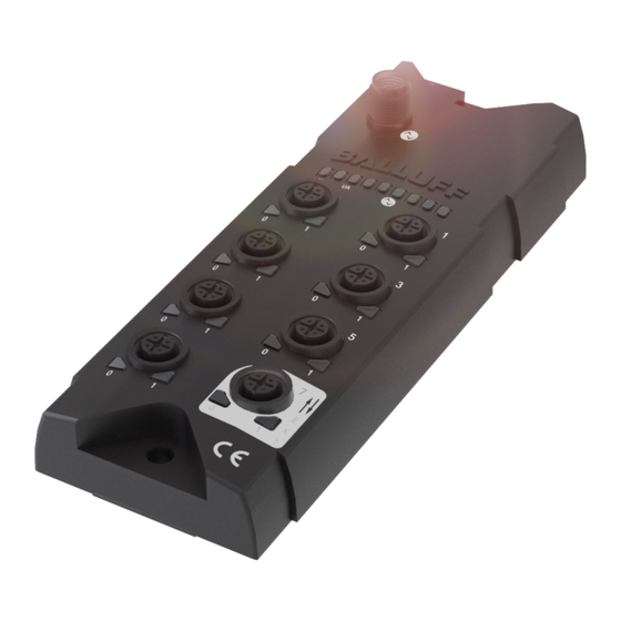
Balluff Network Interface / IO-Link BNI IOL-104-S02-R012 First Steps 3.1. Connection Overview Figure 3-1: Connection overview BNI IOL-104-S02-R012 1 Mounting hole 9 Port 6 2 Label 10 Port 4 3 Status LED: communication 11 Port 2 4 Port 1 12 Port 0... -
Page 7: Mechanical Connection
IO-Link The IO-Link connection is established via an M12 connector (A-coded, male). connection IO-Link (M12, A-coded, male) Function Supply voltage for controller/sensors US, +24 V Supply voltage for actuators UA, +24V GND, reference potential C/Q, IO-Link data transmission channel www.balluff.com... -
Page 8: Connecting The Sensor Hub
Balluff Network Interface / IO-Link BNI IOL-104-S02-R012 First Steps Connect ground conductor to the functional ground connection, if available. Connecting the Connect the incoming IO-Link cable to the sensor hub. sensor hub Note! A standardized sensor cable is used to connect to the higher-level IO-Link master module. -
Page 9: Extension Port Configuration
First Steps The BNI IOL-104-S02-R012 module gives you the ability to use the No. 7 slot in various ways. By default, it is used as a digital Input slot, where both pin 2 and pin 4 can be used as a digital input. -
Page 10: Configuration: "Extension Off
Balluff Network Interface / IO-Link BNI IOL-104-S02-R012 Configuration: "Extension Off" 4.1. IO-Link Data BNI IOL-104-S02-R012 extension off Transmission rate COM2 (38.4 kbaud) Minimum cycle time 4,5 ms Process data length 4 byte input 4.2. Process Byte Data/Input Data Byte www.balluff.com... -
Page 11: Parameter Data/Demand Data
Device ID 3 bytes 0x05 0B 40 Vendor name 8 bytes BALLUFF Vendor text 16 bytes www.balluff.com Product 20/24 BNI IOL-104-S02-R012 name bytes Product ID 7 bytes BNI0090 Product text 16 bytes Sensor Hub M12 Serial number 16 bytes Hardware... -
Page 12: Inversion Of The Inputs 40Hex
Balluff Network Interface / IO-Link BNI IOL-104-S02-R012 Configuration: "Extension Off" Inversion of the Byte inputs 40 Sub- index Inversion of port (x): 0 – Normal 1 - Inverted. Voltage Byte monitoring Sub- index www.balluff.com... -
Page 13: Configuration: Extended With Bni Iol-104-S02-R012
Configuration: extended with BNI IOL-104-S02-R012 5.1. IO-Link Data BNI IOL-104-S02-R012 extended with BNI IOL-104-S02-R012 Transmission rate COM2 (38.4 kbaud) Minimum cycle time 6,8 ms Process data length 8 byte input 5.2. Process Byte Data/Input Data Byte www.balluff.com... - Page 14 Balluff Network Interface / IO-Link BNI IOL-104-S02-R012 Configuration: extended with BNI IOL-104-S02-R012 Byte Extension port Byte Extension port www.balluff.com...
-
Page 15: Parameter Data/Demand Data
Configuration: extended with BNI IOL-104-S02-R012 5.3. Parameter SPDU Parameter Data Access Default value Data/Demand width rights Index Index Subin Data Vendor ID 2 bytes 0378 Device ID 3 bytes 0x05 0B 41 Vendor name 8 bytes BALLUFF Vendor text 16 bytes www.balluff.com... -
Page 16: Inversion Of The Inputs 40Hex
Balluff Network Interface / IO-Link BNI IOL-104-S02-R012 Configuration: extended with BNI IOL-104-S02-R012 Inversion of the Byte inputs 40 Sub- index Byte Sub- index Extension port Inversion of port (x): 0 - Normal 1 - Inverted www.balluff.com... -
Page 17: Voltage Monitoring 44Hex
Configuration: extended with BNI IOL-104-S02-R012 Voltage Byte monitoring Sub- index Byte Sub- index Extension port Setting the The serial number has a default value of 16x00 serial number In order to use the "Identity" master validation mode, a serial number can be set using this parameter. -
Page 18: Configuration Extended With Valve Terminal Connector With 22/24 Valves
Balluff Network Interface / IO-Link BNI IOL-104-S02-R012 Configuration Extended with Valve Terminal Connector with 22/24 Valves 6.1. IO-Link Data BNI IOL-104-S02-R012, extended with valve terminal connector with 22/24 valves Transmission rate COM2 (38.4 kbaud) Minimum cycle time 5.5 ms Process data length 4 byte input, 4 byte output 6.2. -
Page 19: Process Data/ Output Data
Configuration Extended with Valve Terminal Connector with 22/24 Valves 6.3. Process Byte Data/ Output Data Valve terminal on extension port * No function for V013 Byte Valve terminal on extension port * No function for V013 www.balluff.com... -
Page 20: Parameter Data/Demand Data
Balluff Network Interface / IO-Link BNI IOL-104-S02-R012 Configuration Extended with Valve Terminal Connector with 22/24 Valves 6.4. Parameter SPDU Parameter Data Access Default value Data/Demand Index Index Sub- width rights index Data Vendor ID 2 bytes 0378 0x05 0B 42... -
Page 21: Inversion Of The Inputs 40Hex
Configuration Extended with Valve Terminal Connector with 22/24 Valves Inversion of the Byte inputs 40 Sub- index Inversion of port (x): 0 - Normal 1 - Inverted www.balluff.com... -
Page 22: Safe State Of Outputs 42Hex
Balluff Network Interface / IO-Link BNI IOL-104-S02-R012 Configuration Extended with Valve Terminal Connector with 22/24 Valves Safe state of The safe state parameter makes it possible to configure the outputs in case of a fault. If no IO- Outputs 42 Link communication is possible or the "valid flag"... - Page 23 Configuration Extended with Valve Terminal Connector with 22/24 Valves Byte Index Valve terminal on extension port * No function for V013 Byte Index Valve terminal on extension port Value Output state Output is 0V Output is 24V Current status is maintained Not defined www.balluff.com...
-
Page 24: Voltage Monitoring 44Hex
Balluff Network Interface / IO-Link BNI IOL-104-S02-R012 Configuration Extended with Valve Terminal Connector with 22/24 Valves Voltage Byte monitoring Index Byte Index Valve terminal on extension port www.balluff.com... -
Page 25: Monitoring The Outputs 45Hex
The serial number has a default value of 16x00 serial number In order to use the "Identity" master validation mode, a serial number can be set using this parameter. This prevents a device from connecting to the wrong master port. www.balluff.com... -
Page 26: Error Codes/ Errors
Balluff Network Interface / IO-Link BNI IOL-104-S02-R012 Configuration Extended with Valve Terminal Connector with 22/24 Valves 6.5. Error Codes/ Error code Description Errors 0x8011 Index not available 0x8012 Subindex not available 0x8023 Access denied 0x8033 Parameter length overrun 0x8034 Parameter length underrun... -
Page 27: Io-Link Functions
The factory settings on the device can be restored by running the Factory "restore factory settings" system command. Settings 0x82 must be written to Index 2 Subindex 0 for the command. The extension port setting is not reset in this process. www.balluff.com... -
Page 28: Technical Data
Balluff Network Interface / IO-Link BNI IOL-104-S02-R012 Technical Data 8.1. Dimensions 8.2. Mechanical Data Housing material Plastic, resistant, Fortron 6165 A6 IO-Link Port IO-Link port M12, A-coded, male I/O ports M12x1, A-coded, female (8 piece) Weight 430 g Dimension (L × W × H, without... -
Page 29: Function Indicators
Indicators LED indicator Indicator Function module status Green No communication Green, negatively pulsed Communication OK US1 LED Green Sensor power supply is OK Undervoltage < 18 V UA LED Green Actuator power supply is OK Undervoltage < 18 V www.balluff.com... -
Page 30: Digital Led Indicators For Inputs/Outputs
Balluff Network Interface / IO-Link BNI IOL-104-S02-R012 Function Indicators Digital LED LED 2, input/output on Pin 4 and LED 1, input/output on Pin 2 indicators for Indicator Request / Signal inputs/outputs Yellow Input/output signal = 1 Sensor power supply short-circuit... -
Page 31: Appendix
Appendix 10.1. Type Code BNI IOL-104-S02-R012 Balluff Network Interface IO-Link interface Functions 104 = 16 inputs Variants S02 = with IO-Link 1.1 extension port Mechanical configuration R012 = Plastic housing, resistant, Fortron 6165 A6 Bus connection: 1x M12x1 external thread, I/O ports: 8 x M12x1, internal thread 10.2. - Page 32 Balluff GmbH Schurwaldstrasse 9 73765 Neuhausen a.d.F. Germany Phone +49 7158 173-0 Fax +49 7158 5010 www.balluff.com balluff@balluff.de...
Need help?
Do you have a question about the BNI IOL-104-S02-R012 and is the answer not in the manual?
Questions and answers