
Related Manuals for Balluff BNI IOL-302-002-E012


Summary of Contents for Balluff BNI IOL-302-002-E012
- Page 1 BNI IOL-302-002-E012 IO-Link 1.1 sensor/actuator hub with extension port User's Guide...
-
Page 2: Table Of Contents
Balluff Network Interface / IO-Link BNI IOL-302-002-E012 Contents General 1.1. Structure of the Manual 1.2. Typographical Conventions Enumerations Actions Syntax Cross-references 1.3. Symbols 1.4. Abbreviations 1.5. Deviating views Safety 2.1. Intended use 2.2. Installation and Startup 2.3. General Safety Notes 2.4. - Page 3 8.4. Resetting to Factory Settings Technical Data 9.1. Dimensions 9.2. Mechanical Data 9.3. Electrical Data 9.4. Operating conditions Function indicators 10.1. Function indicators LED indicator module status Digital LED indicators for inputs/outputs Extension port Appendix 11.1. Type code 11.2. Ordering information www.balluff.com...
-
Page 4: General
Balluff Network Interface / IO-Link BNI IOL-302-002-E012 General 1.1. Structure of the The manual is organized so that the sections build on one another. Manual Chapter 2: Basic Safety Information. …….. 1.2. Typographical The following typographical conventions are used in this manual. -
Page 5: Safety
BNI modules caused by such aggressive media. Note In the interests of product improvement, Balluff GmbH reserves the right to change the technical data of the product and the content of this manual at any time without notice. Attention! Before maintenance, disconnect the device from the power supply. -
Page 6: First Steps
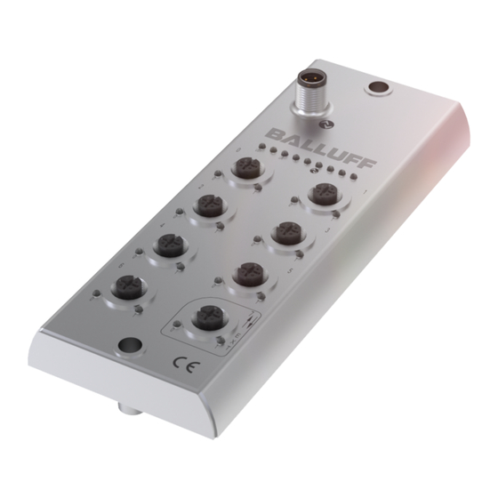
Balluff Network Interface / IO-Link BNI IOL-302-002-E012 First Steps 3.1. Connection Overview Figure 3-1: Connection overview BNI IOL-302-002-E012 1 Mounting hole/ground 8 Port 6 2 Status LED: communication 9 Port 4 3 Port 1 10 Port 2 4 Port 3... -
Page 7: Mechanical Connection
IO-Link The IO-Link connection is established via an M12 connector (A-coded, male). connection IO-Link (M12, A-coded, male) Requirement Supply voltage for controller/sensors US, +24V Supply voltage for actuators UA, +24V GND, reference potential C/Q, IO-Link data transmission channel www.balluff.com... -
Page 8: Connecting The Sensor Hub
Balluff Network Interface / IO-Link BNI IOL-302-002-E012 First Steps Connecting the Connect ground conductor to the functional ground connection, if available. sensor hub Connect the incoming IO-Link cable to the sensor hub. Note A standardized sensor cable is used to connect to the higher-level to the IO-Link master module. -
Page 9: General Configuration
Configuration Index 55 value configuration BNI IOL-302-002-E012 BNI IOL-302-002-E012 with BNI IOL-302-002-E012 BNI IOL-302-002-E012 with BNI IOL-751-V08-K007 BNI IOL-302-002-E012 with BNI IOL-751-V10-K007 BNI IOL-302-002-E012 with BNI IOL-751-V13-K007 Note The "Factory reset" command does not affect the configuration of the extension port in any way. -
Page 10: Configuration: "Extension Off
Balluff Network Interface / IO-Link BNI IOL-302-002-E012 Configuration: "Extension Off" 5.1. IO-Link data BNI IOL-302-002-E012 extension off Transmission rate COM2 (38.4 kBaud) Minimum cycle time 4.0 ms Process data length 2 byte input, 2 byte output 5.2. Process Byte Data/Input Data 5.3. -
Page 11: Parameter Data / Demand Data
Vendor ID 2 bytes 0378 Device ID 3 bytes 0x05 0D 80 Vendor Name BALLUFF Vendor text www.balluff.com Product BNI IOL-302-002-E012 Name Product ID BNI00AR Product text M12 sensor/actuator hub Serial number 16 bytes Hardware revision Firmware revision Application-... -
Page 12: Inversion Of The Inputs 40Hex
Balluff Network Interface / IO-Link BNI IOL-302-002-E012 Configuration: "Extension Off" Inversion of the Byte inputs 40 Sub- Index Inversion of port (x): 0 – Normal 1 - Inverted. Configuration Byte inputs/outputs Sub- 41hex index Direction of port (x): 0 – Input 1 –... -
Page 13: Safe State Of The Outputs On Pin 4 42Hex
Byte outputs on Pin 4 Sub- Index Safe state of the Byte outputs on Pin 2 Sub- Index Value Output state Output is 0V Output is 24V Current status is maintained Not defined Voltage Byte monitoring 44 Sub- Index www.balluff.com... -
Page 14: Monitoring The Outputs 45Hex
Balluff Network Interface / IO-Link BNI IOL-302-002-E012 Configuration: "Extension Off" Monitoring the Byte outputs 45 Sub- Index Monitoring the Byte outputs 46 Sub- Index Setting the The serial number has a default value of 16x00hex. serial number In order to use the "Identity" master validation mode, a 54hex serial number can be set using this parameter. -
Page 15: Configuration: Extended With Bni Iol-302-002-E012
Configuration: Extended with BNI IOL-302-002-E012 6.1. IO-Link data BNI IOL-302-002-E012 extended with BNI IOL-302-002-E012 Transmission rate COM2 (38.4 kBaud) Minimum cycle time 5.0 ms Process data length 4 bytes input, 4 bytes output 6.2. Process Byte Data/Input Data Byte Extension port... -
Page 16: Process Data/ Output Data
Balluff Network Interface / IO-Link BNI IOL-302-002-E012 Configuration: Extended with BNI IOL-302-002-E012 6.3. Process Data/ Byte Output Data Byte Extension port www.balluff.com... -
Page 17: Parameter Data / Demand Data
Configuration: Extended with BNI IOL-302-002-E012 6.4. Parameter Data SPDU Parameter Data Access Default value / Demand Data width rights Index Index Sub- index Vendor ID 2 bytes 0378 0Ahe Device ID 3 bytes 0x05 0D 81 Vendor Name BALLUFF Vendor text www.balluff.com... -
Page 18: Inversion Of The Inputs 40Hex
Balluff Network Interface / IO-Link BNI IOL-302-002-E012 Configuration: Extended with BNI IOL-302-002-E012 Inversion of the Byte inputs 40 Sub- Index Byte Sub- Index Extension port Inversion of port (x): 0 - Normal 1 - Inverted www.balluff.com... -
Page 19: Configuration Of Inputs/Outputs 41Hex
Configuration: Extended with BNI IOL-302-002-E012 Configuration Byte inputs/outputs Sub- 41hex Index Byte Sub- Index Extension port Direction of port (x): 0 – Input 1 – Output Safe state of The safe state parameter makes it possible to configure the outputs in case of a fault. If no Outputs 42 IO-Link communication is possible or the "valid flag"... -
Page 20: Safe State Of The Outputs On Pin 4 42Hex
Balluff Network Interface / IO-Link BNI IOL-302-002-E012 Configuration: Extended with BNI IOL-302-002-E012 Safe state of Byte the outputs on Pin 4 42 Sub- Index Byte Sub- Index Extension port www.balluff.com... -
Page 21: Safe State Of The Outputs On Pin 2 43Hex
Configuration: Extended with BNI IOL-302-002-E012 Safe state of Byte the outputs on Pin 2 43 Sub- Index Byte Sub- Index Extension port Value Output state Output is 0V Output is 24V Current status is maintained Not permitted www.balluff.com... -
Page 22: Voltage Monitoring 44Hex
Balluff Network Interface / IO-Link BNI IOL-302-002-E012 Configuration: Extended with BNI IOL-302-002-E012 Voltage Byte monitoring Sub- Index Byte Sub- Index Extension port Setting the The serial number has a default value of 16x00 hex. serial number In order to use the "Identity" master validation mode, a serial number can be set using this parameter. -
Page 23: Configuration Extended With Valve Terminal Connector With 22/24 Valves
Configuration Extended with Valve Terminal Connector with 22/24 Valves 7.1. IO-Link data BNI IOL-302-002-E012, extended with valve terminal connector with 22/24 valves Transmission rate COM2 (38.4 kBaud) Minimum cycle time 5.1 ms Process data length 2 byte input, 6 byte output 7.2. -
Page 24: Process Data/Output Data
Balluff Network Interface / IO-Link BNI IOL-302-002-E012 Configuration Extended with Valve Terminal Connector with 22/24 Valves 7.3. Process Data/ Byte Output Data Byte Valve terminal on extension port * No function for V013 Byte Valve terminal on extension port * No function for V013... -
Page 25: Parameter Data / Demand Data
0x05 0D 82 Device ID 3 bytes 0x05 0D 83 0x05 0D 84 0Bhe Vendor BALLUFF Name Vendor text www.balluff.com BNI IOL-302-002-E012 with BNI IOL-751-V08-K007 Product BNI IOL-302-002-E012 with Name BNI IOL-751-V10-K007 BNI IOL-302-002-E012 with BNI IOL-751-V13-K007 BNI00AR with BNI006N Product ID... -
Page 26: Inversion Of The Inputs 40Hex
Balluff Network Interface / IO-Link BNI IOL-302-002-E012 Configuration Extended with Valve Terminal Connector with 22/24 Valves Inversion of Byte the inputs Sub- Index Inversion of port (x): 0 - Normal 1 - Inverted Configuration Byte inputs/outputs Direction of port (x): 0 –... -
Page 27: Safe State Of Outputs 42Hex
The following statuses can be configured for each pin. Safe state of the Byte outputs on Pin 4 Sub- Index Byte Sub- index Valve terminal on extension port * No function for V013 Byte Sub- index Valve terminal on extension port www.balluff.com... -
Page 28: Safe State Of The Outputs On Pin 2 43Hex
Balluff Network Interface / IO-Link BNI IOL-302-002-E012 Configuration Extended with Valve Terminal Connector with 22/24 Valves Byte Sub- Index Valve terminal on extension port * No function for V013 Byte Sub- Index Valve terminal on extension port Safe state of... -
Page 29: Voltage Monitoring 44Hex
Configuration Extended with Valve Terminal Connector with 22/24 Valves Voltage Byte monitoring Sub- Index Byte Sub- Index Valve terminal on extension port www.balluff.com... -
Page 30: Monitoring The Outputs 45Hex
Balluff Network Interface / IO-Link BNI IOL-302-002-E012 Configuration Extended with Valve Terminal Connector with 22/24 Valves Monitoring Byte the outputs Sub- Index Byte Sub- Index Extension port * No function for V013 Byte Sub- index Extension port * No function for V013... -
Page 31: Errors
IO-Link Revision 1.1 Event Code Description 0x5111 Low sensor voltage (US) 0x5112 Low actor voltage (UA) 0x7710 Short circuit 0x8DF0 Retry at the extension port 0x8DF1 Device lost at the extension port 0x8DF2 Wrong device at the extension port www.balluff.com... -
Page 32: Io-Link Functions
Balluff Network Interface / IO-Link BNI IOL-302-002-E012 IO-Link functions 8.1. IO-Link This device can be operated with an IO-Link master according to IO-Link version 1.0 and Version 1.0 / version 1.1. Version-specific functions such as data storage (version 1.1) are only supported in combination with a suitable IO-Link master. -
Page 33: Technical Data
Operating temperature –5 °C … +70 °C conditions Storage temperature –25 °C … +70 °C Immunity tests: EN 61000-6-2:2005 AC:2005 Emission tests: EN 61000-6-4:2007 A1:2011 IP69 (only when plugged-in and screwed Degree of protection together) Vibration/shock EN 60068 Part 2-6/27 www.balluff.com... -
Page 34: Function Indicators
Balluff Network Interface / IO-Link BNI IOL-302-002-E012 Function indicators 10.1. Function indicators LED indicator Indicator Function module status Green No communication Green, negative pulsed Communication OK US1 LED Green Module supply OK Undervoltage < 18 V UA LED Green Actuator supply OK Undervoltage <... -
Page 35: Digital Led Indicators For Inputs/Outputs
"Digital LED indicators for inputs/outputs" can be used. Status Function Green IO-Link – connection active Green, flashing No IO-Link connection or faulty IO-Link device Flashing red rapidly Incorrect IO-Link device or incorrect configuration (0x55) Short circuit www.balluff.com... -
Page 36: Appendix
Balluff Network Interface / IO-Link BNI IOL-302-002-E012 Appendix 11.1. Type code BNI IOL-302-002-E012 Balluff Network Interface IO-Link interface Functions 302 = 16 inputs/outputs Variants 002 = with IO-Link 1.1 extension port Mechanical configuration E012 = Stainless steel V4A Bus connection: 1x M12x1 external threads, I/O ports: 8 x M12x1, internal thread 11.2. - Page 37 Notes www.balluff.com...
-
Page 38: Www.balluff.com
Balluff GmbH Schurwaldstrasse 9 73765 Neuhausen a.d.F. Germany Phone +49 7158 173-0 Fax +49 7158 5010 www.balluff.com balluff@balluff.de...
Need help?
Do you have a question about the BNI IOL-302-002-E012 and is the answer not in the manual?
Questions and answers