Table of Contents
Advertisement
Advertisement
Table of Contents

Related Manuals for Balluff BNI IOL-104-S02-Z012


Summary of Contents for Balluff BNI IOL-104-S02-Z012
- Page 1 BNI IOL-104-S02-Z012 IO-Link 1.1 Sensor Hub with extension port User´s Guide...
-
Page 2: Table Of Contents
Parameter Data/ Device Configuration Inversion of the inputs 40hex Voltage monitoring 44hex Setting the serial number 54hex Configuration of the extension port 55hex Configuration: BNI IOL-104-S02-Z012 extended with BNI IOL-104-S02-Z012 Extension Port Configuration IO-Link Data Process Data/ Input Data Process Data/ Output Data... - Page 3 Balluff Network Interface / IO-Link Configuration of the extension port 55hex Configuration: BNI IOL-104-S02-Z012 extended with 22/24 Valve Terminal Extension Port Configuration IO-Link Data Process Data/ Input Data Process Data/ Output Data Parameter Data/ Identification Data and Device Parameters Parameter Data/Demand Data...
-
Page 4: User Instructions
User Instructions About this Manual This manual describes the Balluff IO-Link I/O module, also called a sensor/actuator hub. The IO-Link protocol is used to link to the higher-level master module. In terms of function, this compact, cost-effective module is similar to a passive splitter box; it records digital sensor signals and transmits them over the IO-Link interface. -
Page 5: Safety
Before maintenance, disconnect the device from the power supply. Note In the interests of product improvement, Balluff GmbH reserves the right to change the technical data of the product and the content of this manual at any time without notice. -
Page 6: First Steps
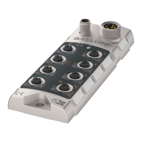
Balluff Network Interface / IO-Link First Steps Connection overview Figure 3.1: Connection overview 1 Mounting hole Port 6 2 Label 10 Port 4 3 Communication state 11 Port 2 4 Port 1 12 Port 0 5 Port 3 13 IO-Link interface... -
Page 7: Mechanical Connection
The BNI IOL modules are fastened with using 2 M6 screws and 2 spacers . Connection Electrical The BNI IOL-104-S02-Z012 modules do not require a separate supply voltage connection. Connection Supply voltage is provided via the IO-Link interface and the higher-level IO-Link master module. -
Page 8: Connecting The Sensor Hub
Balluff Network Interface / IO-Link First Steps Connect ground conductor to the FE terminal, if available. Connecting the Connect the incoming IO-Link cable to the sensor hub. sensor hub Note A standardized sensor cable is used to connect to the higher-level IO-Link master module. -
Page 9: Device Functions
Balluff Network Interface / IO-Link First Steps Device Device Functionality functions 16 Digital Inputs with single channel monitoring, BNI IOL-104-S02-Z012 IO-Link V1.1 with extension port Extension Port These modules provide using the Port 7 in various ways. By default, it is used as a digital input port, where both pin 2 and pin 4 can be used as a digital input. -
Page 10: Configuration Overview
Balluff Network Interface / IO-Link Configuration Overview Introduction This document provide information about the device. The device can be configured in 5 different modes. By this, you have 5 hardware setups. Before the detailed technical data, here is an overview and a summary about the main features and properties. -
Page 11: Configuration Of The Extension Port
Balluff Network Interface / IO-Link Configuration Overview Configuration Following devices can be connected to the Extension Port of the Extension Port Configuration Use Case Device alone (Extension Port not active) Device with same Device Device with BNI IOL-751-V08-K007 Device with BNI IOL-751-V10-K007 Device with BNI IOL-751-V13-K007 The device which is connected to the Extension Port is called as “Second Device”... -
Page 12: Data Handling With The Extension Port
Balluff Network Interface / IO-Link Configuration Overview Data handling When the Extension Port is activated, the content and length of the Process Data (or ISDU) is with the calculated as the union of the process data (or ISDU) provided by the two parties. -
Page 13: Configuration: Bni Iol-104-S02-Z012, Extension Port Off
Balluff Network Interface / IO-Link Configuration: BNI IOL-104-S02-Z012, extension port off Extension Port Factory default configuration is Extension Port off. Configuration Configuration ISDU Index 55 value Device alone (Extension Port not active) Device with same device Device with BNI IOL-751-V08-K007... -
Page 14: Process Data/ Input Data
Balluff Network Interface / IO-Link Configuration: BNI IOL-104-S02-Z012, extension port off Process Data/ The first two bytes are the input state. Last two bytes are the diagnostic info. Input Data Byte Byte Process Data/ Not available, no process data output Output Data www.balluff.com... -
Page 15: Parameter Data/ Identification Data And Device Parameter
Balluff Network Interface / IO-Link Configuration: BNI IOL-104-S02-Z012, extension port off Parameter Data/ ISDU Data Access Identification Parameter Default value Sub- width rights Index Index Data and index Device Vendor ID 2 bytes 0378 Parameter Device ID 3 bytes 05 0E 50... -
Page 16: Inversion Of The Inputs 40Hex
Balluff Network Interface / IO-Link Configuration: BNI IOL-104-S02-Z012, extension port off Inversion of Byte the inputs Sub- index Inversion of port (x): 0 – Normal 1 – Inverted Voltage Byte monitoring Sub- index Setting the The serial number has a factory default value, 16 ASCII characters, example: 0E-G550389-1D- serial number 26. -
Page 17: Configuration: Bni Iol-104-S02-Z012 Extended With Bni Iol-104-S02-Z012
Balluff Network Interface / IO-Link Configuration: BNI IOL-104-S02-Z012 extended with BNI IOL-104-S02-Z012 Extension Port Configuration ISDU Index 55 value Configuration Device alone (Extension Port not active) Device with same device Device with BNI IOL-751-V08-K007 Device with BNI IOL-751-V10-K007 Device with BNI IOL-751-V13-K007... -
Page 18: Process Data/ Input Data
Balluff Network Interface / IO-Link Configuration: BNI IOL-104-S02-Z012 extended with BNI IOL-104-S02-Z012 Process Data/ Byte Input Data Byte Byte Same device on Extension port Byte Same device on Extension port Process Data/ Not available, no process data output. Output Data... -
Page 19: Parameter Data/ Identification Data And Device Parameter
Balluff Network Interface / IO-Link Configuration: BNI IOL-104-S02-Z012 extended with BNI IOL-104-S02-Z012 Parameter Data/ ISDU Access Data Parameter Default value Identification Sub- rights width Index Index index Data and Device Vendor ID 2 bytes 0378 Parameter Device ID 3 bytes... -
Page 20: Inversion Of The Inputs 40Hex
Balluff Network Interface / IO-Link Configuration: BNI IOL-104-S02-Z012 extended with BNI IOL-104-S02-Z012 Inversion of the Byte inputs Sub- index Byte Sub- index Same device on Extension port Inversion of port (x): 0 – Normal 1 – Inverted www.balluff.com... -
Page 21: Voltage Monitoring 44Hex
Balluff Network Interface / IO-Link Configuration: BNI IOL-104-S02-Z012 extended with BNI IOL-104-S02-Z012 Voltage Byte monitoring Sub- index Byte Sub- index Same device on Extension Port Setting the The serial number has a factory default value, 16 ASCII characters, example: 0E-G550389-1D- serial number 26. -
Page 22: Configuration: Bni Iol-104-S02-Z012 Extended With 22/24 Valve Terminal
Device with BNI IOL-751-V08-K007 Device with BNI IOL-751-V10-K007 Device with BNI IOL-751-V13-K007 However BNI IOL-104-S02-Z012 is a digital input module, which does not require UA Voltage, this configuration with Valve Terminal requires the UA Voltage to drive the Valve Terminal’s output. -
Page 23: Process Data/ Input Data
Balluff Network Interface / IO-Link Configuration: BNI IOL-104-S02-Z012 extended with 22/24 Valve Terminal Process Data/ Byte Input Data Byte Process Data/ Byte Output Data Valve terminal on extension port * No function for BNI IOL-751-V13-K007 Byte Valve terminal on extension port * No function for BNI IOL-751-V13-K007 www.balluff.com... -
Page 24: Parameter Data/ Identification Data And Device Parameters
Balluff Network Interface / IO-Link Configuration: BNI IOL-104-S02-Z012 extended with 22/24 Valve Terminal Parameter Data/ ISDU Data Access Parameter Default value Identification Sub- width rights Index Index index Data and Device Vendor ID 2 bytes 0378 Parameters 05 0E 52... -
Page 25: Inversion Of The Inputs 40Hex
Balluff Network Interface / IO-Link Configuration: BNI IOL-104-S02-Z012 extended with 22/24 Valve Terminal Inversion of the Byte inputs Sub- index Inversion of port (x): 0 – Normal 1 – Inverted Safe state of the The safe state parameter makes it possible to configure the outputs in case of a fault. If no outputs IO-Link communication is possible or the "valid flag"... - Page 26 Balluff Network Interface / IO-Link Byte Sub- index Valve terminal on extension port Byte Sub- index Valve terminal on extension port * No function for BNI IOL-751-V13-K007 Byte Sub- index Valve terminal on extension port www.balluff.com...
-
Page 27: Voltage Monitoring 44Hex
Balluff Network Interface / IO-Link Configuration: BNI IOL-104-S02-Z012 extended with 22/24 Valve Terminal Voltage Byte monitoring Sub- index Byte Sub- index Valve terminal on extension port www.balluff.com... -
Page 28: Output Monitoring 45Hex
Balluff Network Interface / IO-Link Configuration: BNI IOL-104-S02-Z012 extended with 22/24 Valve Terminal Output Byte monitoring Sub- index Valve terminal on extension port * No function for BNI IOL-751-V13-K007 Byte Sub- index Valve terminal on extension port * No function for BNI IOL-751-V13-K007... -
Page 29: Error Codes And Events
Balluff Network Interface / IO-Link Error Codes and Events Error Codes/ Error code Description Errors 0x8011 Index not available 0x8012 Subindex not available 0x8023 Access denied 0x8033 Parameter length overrun 0x8034 Parameter length underrun 0x8035 Function not available 0x8036 Function temporarily unavailable Events IO-Link Revision 1.0... -
Page 30: Io-Link Functions
Balluff Network Interface / IO-Link IO-Link Functions IO-Link This device can be operated with an IO-Link master according to IO-Link version 1.0, and Version 1.0/ version 1.1. Version-specific functions such as data storage (version 1.1) are only supported in combination with a suitable IO-Link master. -
Page 31: Technical Data
Balluff Network Interface / IO-Link Technical Data Dimensions Mechanical Housing material Die-cast zinc housing Data IO-Link port IO-Link port M12, A-coded, male PNP I/O ports M12x1, A-coded, female (8 piece) Weight approx. 530 g Dimensions (H x W x D, without... -
Page 32: Function Indicators
Balluff Network Interface / IO-Link Function Indicators Function Indicators LED 0 LED 1 LED indicator Indicator Function module status Green No communication Green, flashing IO-Link Communication OK Green Module supply OK Undervoltage < 18 V Module without voltage Green Actuator power supply OK Undervoltage <... -
Page 33: Appendix
Balluff Network Interface / IO-Link Appendix Type Code BNI IOL-xxx-xxx-Zxxx Balluff Network Interface IO-Link interface Functions 104 = 16 PNP inputs Variants S02 = with IO-Link 1.1 extension port and single channel monitoring Mechanical configuration = die-cast zinc housing Z012 = bus connection and power supply: 1x M12x1 external thread,... - Page 34 Balluff GmbH Schurwaldstrasse 9 73765 Neuhausen a.d.F. Germany Tel. +49 7158 173-0 Fax +49 7158 5010 www.balluff.com balluff@balluff.de...
Need help?
Do you have a question about the BNI IOL-104-S02-Z012 and is the answer not in the manual?
Questions and answers