Table of Contents
Advertisement
Quick Links
Advertisement
Table of Contents

Subscribe to Our Youtube Channel
Related Manuals for Balluff BIS V-6106


Summary of Contents for Balluff BIS V-6106
- Page 1 BIS V-6106 Ethernet/IP Technical Reference, Operating Manual english...
- Page 2 www.balluff.com...
-
Page 3: Table Of Contents
BIS V-6106 Ethernet/IP™ Processor Unit User Instructions About This Manual Typographical Conventions Symbols Meaning of Warnings Abbreviations Safety Intended Use General Safety Notes Basic Knowledge Operating Principle of Identification Systems Product Description Control Function Data Integrity Read/Write Heads H1…H4 EtherNet/IP™... -
Page 4: User Instructions
BIS V-6106 Ethernet/IP™ Processor Unit User Instructions 1.1 About This This manual describes the processor unit for BIS V-6106 Identification Systems and startup Manual instructions for immediate operation. 1.2 Typographical The following conventions are used in this manual: Conventions Actions Action instructions are indicated by a preceding triangle. The result of an action is indicated by an arrow. -
Page 5: Abbreviations
BIS V-6106 Ethernet/IP™ Processor Unit User Instructions Address Resolution Protocol 1.5 Abbreviations Balluff Identification System Common Industrial Protocol Code Present Cyclic Redundancy Check DHCP Dynamic Host Configuration Protocol I/O port Digital input and output port Electronic Data Sheet EEPROM Electrical Erasable and Programmable ROM EIRP Equivalent Isotropically Radiated Power... -
Page 6: Safety
Safety 2.1 Intended Use The BIS V-6106 processor unit is a component of the BIS V identification system. It is used for linking to a host computer (PLC, PC) within the identification system. It may be used only for this purpose in an industrial environment corresponding to Class A of the EMC Law. -
Page 7: Basic Knowledge
BIS V-6106 Ethernet/IP™ Processor Unit Basic Knowledge 3.1 Operating The BIS V Identification System is classified as a non-contact system with read and write Principle of capabilities. This makes it possible to not only convey information that is programmed Identification permanently in the data carrier, but also to collect and pass on current information. -
Page 8: Control Function
BIS V-6106 Ethernet/IP™ Processor Unit Basic Knowledge 3.3 Control Function The processor unit is the link between data carrier and host control system. It manages two-way data transfer between data carrier and R/W head and provides buffer storage. The processor unit uses the R/W head to write data from the host control system to the data carrier or reads the data from the carrier and makes it available to the host control system. -
Page 9: Ethernet/Ip
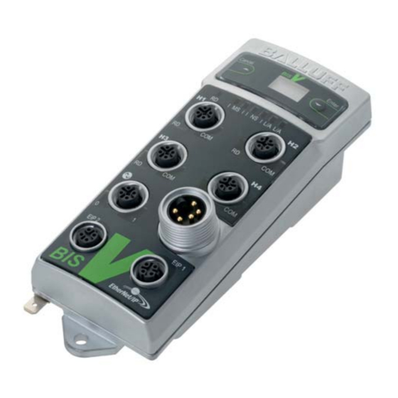
Processor Unit Basic Knowledge 3.5 Read/Write For BIS V-6106-034-C00_, read/write heads in the BIS VM-3 _ _, BIS VL-3 _ _, and BIS VU-3 _ _ Heads H1…H4 series can be connected to terminals H1...H4. BIS V-6106-034-C10_ also supports read/write heads in the BIS C-3 _ _ series (Adapter required). -
Page 10: Io-Link
BIS V-6106 Ethernet/IP™ Processor Unit Basic Knowledge 3.7 IO-Link IO-Link is defined as a standardized point-to-point connection between sensors/actuators and an I/O module. An IO-Link sensor/actuator can send additional communication data (e.g. diagnostics signals) in addition to the binary process signals over the IO-Link interface. -
Page 11: Installation
BIS V-6106 Ethernet/IP™ Processor Unit Installation 4.1 Processor Unit Included in the scope of delivery: Scope of Delivery – BIS V-6106 – 5 × closure cap – Safety Precautions Note Visit www.balluff.com for more information on available software and accessories. 4.2 Processor Unit... -
Page 12: Electrical Connections
BIS V-6106 Ethernet/IP™ Processor Unit Installation 4.3 Electrical Note Connections Make the ground connection either directly or using an RC combination to ground. Connections H1…H4 Read/Write Heads Service/IO-Link USB function Service/IO-Link (master function) EIP1 Ethernet/IP Port 1 EIP2 Ethernet/IP Port 2... -
Page 13: Technical Data
BIS V-6106 Ethernet/IP™ Processor Unit Technical Data Dimensions Figure 1: Dimensions in mm Mechanical Data Housing material Zinc die-cast housing H1…H4 24 V DC - M12 female, 5-pin, A-coded Service/IO-Link (master function) M12 female, 5-pin, A-coded Power 7/8" male, 5-pin EIP port 2... - Page 14 BIS V-6106 Ethernet/IP™ Processor Unit Technical Data Ambient Temperature 0 °C…+60 °C Operating conditions Storage Temperature 0 °C…+60 °C EMC (BIS V-6106-034-C00_) – EN 61000-6-2 – EN 61000-4-2/4/5/6 – Severity level 2A/3A/2A/3A – EN 61000-4-3 80 MHz – 1000 MHz – Severity level 3A 1400 MHz –...
-
Page 15: Startup
BIS V-6106 Ethernet/IP™ Processor Unit Startup EtherNet/IP™ The BIS V-6106 processor unit and the controlling system communicate via Ethernet/IP™ protocol. The Ethernet/IP™ system consists of the following components: – Ethernet/IP™ scanner – Ethernet/IP™ adapter (the BIS V-6106 processor unit in this case) IP Address The processor unit and the controlling system communicate using Ethernet/IP. -
Page 16: Assemblies
BIS V-6106 Ethernet/IP™ Processor Unit Startup Assemblies Instance ID Data length 6.1 Assemblies INPUT OUTPUT CONFIG 6.2 Config Assembly Byte Parameter Description 00–01 Device General configuration of the entire device 02–09 RFID Head 1 Configuration of read/write head 1 10–17 RFID Head 2 Configuration of read/write head 2... - Page 17 BIS V-6106 Ethernet/IP™ Processor Unit Startup Byte Meaning IO-Link port parameter 34+35 IO-Link port function Cycle time Validation type IOL Vendor ID 1 IOL Vendor ID 2 IOL Device ID 1 IOL Device ID 2 IOL Device ID 3 IOL Serial number 1 …...
- Page 18 BIS V-6106 Ethernet/IP™ Processor Unit Startup CRC check The CRC check is a procedure for determining a check value for data in order to be able to recognize transmission errors. If the CRC check is enabled, a status message will be sent when a CRC error is detected.
- Page 19 BIS V-6106 Ethernet/IP™ Processor Unit Startup CRC check The number of usable bytes thus decreases when using the checksum. Balluff data carrier type Memory capacity Usable bytes for CRC_16 BIS M-1_ _-01 752 Byte 658 Byte BIS M-1_ _-02 2000 Byte...
- Page 20 Information about configuring the transmission power for BIS VU read/write heads can be found in the manual for the BIS L read/write head. Manuals are available at www.balluff.com. Head LEDs off This parameter switches off the LEDs on the respective read/write head. This function is configured in the respective read/write head module (only BIS VM and BIS VU).
- Page 21 Processor Unit Startup Tag type The following data carriers are available for the BIS V-6106 processor unit. Note The data carriers contain additional memory ranges for configuration and protected data. These ranges cannot be processed using the BIS V-6106 processor unit.
- Page 22 BIS V-6106 Ethernet/IP™ Processor Unit Startup Note Tag type To achieve the read times specified on page 63 in dynamic operation, the Tag Type parameter has to be set to "BIS C 32 Byte" or "BIS C 64 Byte" on the respective head. For read/write heads BIS VU:...
- Page 23 BIS V-6106 Ethernet/IP™ Processor Unit Startup Parameter server, Automatic upload (IO-Link slave IO-Link master) or download (IO-Link master IO-Link optional slave) can be switched on using this parameter. For automatic upload, the parameter configuration is read when an IO-Link device is plugged in.
-
Page 24: Device Functions
BIS V-6106 Ethernet/IP™ Processor Unit Device Functions 7.1 Function Two buffers are needed to exchange data and commands between the processor unit and the Principle of the host control system (input buffer and output buffer). The buffer contents are exchanged using BIS V-6106... -
Page 25: Process Data Buffer
BIS V-6106 Ethernet/IP™ Processor Unit Device Functions 7.2 Process Data Buffer Output buffer The control commands for the identification system and the data to be written to the data carrier are transmitted via the output buffer. Bit No. Subaddress = Bit... - Page 26 BIS V-6106 Ethernet/IP™ Processor Unit Device Functions Input buffer The input buffer is used to send the data read from the identification system, the designations, and the status codes to the host control system. Bit No. Subaddress = Bit Header...
- Page 27 BIS V-6106 Ethernet/IP™ Processor Unit Device Functions Input buffer Status codes Status code Description of Function Everything OK. Job cannot be run because there is no data carrier in range of the read/write head. Cannot read the data carrier. Data carrier was removed from the R/W head's range during reading.
- Page 28 BIS V-6106 Ethernet/IP™ Processor Unit Device Functions Structure of the Command designator 01 : Read from data carrier commands for read/write heads Reads USER data from the specified start address. The data length is equal to the number of bytes.
- Page 29 BIS V-6106 Ethernet/IP™ Processor Unit Device Functions Structure of the Command Identifier 81 : Read Data Carrier with 24-bit Addresses commands for read/write heads When assigning addresses to data carriers with expanded memory, the start address and number of bytes can be specified as 24-bit values. Information about executing the command as...
- Page 30 BIS V-6106 Ethernet/IP™ Processor Unit Device Functions Structure of the Command Identifier 02 : Write to Data Carrier commands for read/write heads Writes USER data at the specified start address. The data length is equal to the number of bytes.
- Page 31 BIS V-6106 Ethernet/IP™ Processor Unit Device Functions Structure of the Command designator 82 : Write to data carrier with 24-bit addresses commands for read/write heads When assigning addresses to data carriers with expanded memory, the start address and number of bytes can be specified as 24-bit values. Information about executing the command as...
- Page 32 BIS V-6106 Ethernet/IP™ Processor Unit Device Functions Structure of the Command designator 07 : Store the start address for the "Auto Read" function commands for read/write heads Configuring the start address after the data is read with the Auto Read function. For more details, see the “Description of individual parameters”...
- Page 33 BIS V-6106 Ethernet/IP™ Processor Unit Device Functions Structure of the Command designator 09 : Type and serial number commands for read/write heads If a data carrier is recognized in the active read/write zone of the read/write head, this command will return the read-write head type as well as the data carrier type and serial number of the detected data carrier.
- Page 34 BIS V-6106 Ethernet/IP™ Processor Unit Device Functions Structure of the Command designator 11 : Copy data between data carriers commands for read/write heads Copy data from one data carrier to another. The specified number of bytes will be copied from the source start address in the source data carrier to the target start address in the target data carrier.
- Page 35 BIS V-6106 Ethernet/IP™ Processor Unit Device Functions Structure of the Command Identifier 91 : Copy Data Between Data Carriers with 24-bit Addresses commands for read/write heads When assigning addresses to data carriers with expanded memory, the start address and number of bytes can be specified as 24-bit values. Information about executing the command as...
- Page 36 BIS V-6106 Ethernet/IP™ Processor Unit Device Functions Structure of the Command designator 12 : Initialize CRC_16 data check commands for read/write heads The memory area of the data carrier used is prepared for use with a CRC data check. It is initialized by writing USER data with a checksum.
- Page 37 BIS V-6106 Ethernet/IP™ Processor Unit Device Functions Structure of the Command Identifier 92 : Initialize CRC_16 Data Check with 24-bit Addresses commands for read/write heads When assigning addresses to data carriers with expanded memory, the start address and number of bytes can be specified as 24-bit values. Information about executing the command as...
- Page 38 BIS V-6106 Ethernet/IP™ Processor Unit Device Functions Structure of the Command designator 32 : Write constant value to data carrier commands for read/write heads Writes a constant value to the memory area, which is indicated with a start address and number of bytes.
- Page 39 BIS V-6106 Ethernet/IP™ Processor Unit Device Functions Structure of the Command Identifier B2 : Write Constant Value to Data Carrier with 24-bit Addresses commands for read/write heads When assigning addresses to data carriers with expanded memory, the start address and number of bytes can be specified as 24-bit values.
- Page 40 BIS V-6106 Ethernet/IP™ Processor Unit Device Functions Note Specific Details and more information about the available parameters as well as commands for BIS VU-specific commands can be found in the manual of the BIS VU read/write BIS VU read/write head used (Available at www.balluff.com).
- Page 41 BIS V-6106 Ethernet/IP™ Processor Unit Device Functions Specific Command Identifier 41 : Unselect (Undo a Data Carrier Selection) commands for BIS VU read/write The Unselect command undoes one data carrier selection that was carried out with the Select heads command. If a selection is not active, the status will remain unchanged.
- Page 42 BIS V-6106 Ethernet/IP™ Processor Unit Device Functions Specific Command Identifier 42 : Read from EPC commands for BIS VU read/write Reads the EPC memory area of a data carrier that was previously selected with the Select heads command. In Single-Tag mode, that is, if only one data carrier is located in front of the active read/write zone antenna, then the Select command can be disregarded.
- Page 43 BIS V-6106 Ethernet/IP™ Processor Unit Device Functions Specific Command Identifier 43 : Write to EPC commands for BIS VU read/write Writes to the EPC memory area of a data carrier that was previously selected with the Select heads command. In Single-Tag mode, that is, if only one data carrier is located in front of the active read/write zone antenna, then the Select command can be disregarded.
- Page 44 BIS V-6106 Ethernet/IP™ Processor Unit Device Functions Specific Command Identifier 44 : Read from TID commands for BIS VU read/write Reads the TID memory area of a data carrier that was previously selected with the Select heads command. In Single-Tag mode, that is, if only one data carrier is located in front of the active read/write zone antenna, then the Select command can be disregarded.
- Page 45 BIS V-6106 Ethernet/IP™ Processor Unit Device Functions Specific Command Identifier 45 : Configure the Transmission Power commands for BIS VU read/write The transmission power for the antenna (ERP or EIRP), which is specified as a value in quarter heads dBm increments, affects the maximum range of the read/write range of the antenna.
- Page 46 BIS V-6106 Ethernet/IP™ Processor Unit Device Functions Specific Command Identifier 46 : Read out Transmission Power commands for BIS VU read/write Reads out the current transmission power (ERP). The transmission power is returned as a value heads in the form of quarter dBm.
- Page 47 BIS V-6106 Ethernet/IP™ Processor Unit Device Functions Specific Command Identifier 47 : Read from Multiple Data Carriers commands for BIS VU read/write The Read from Multiple Data Carriers reads, depending on the configured type, the EPC or the heads TID of all data carriers that are located in the active read/write area of the antenna.
- Page 48 BIS V-6106 Ethernet/IP™ Processor Unit Device Functions Note Specific As circumstances require, the data must be transmitted over multiple BUS cycles. commands for BIS VU read/write heads Example of a received data frame with 2 EPCs and 12 bytes per EPC (Illustration without bit headers).:...
- Page 49 BIS V-6106 Ethernet/IP™ Processor Unit Device Functions Specific Example of a received data frame with 2 EPCs and 64 bytes per EPC commands for (Illustration without bit headers): BIS VU read/write heads EPC 1 Length: 48 bytes (34 EPC: E2 FF 00 00 E2 11 90 22 E2 03 01 27 33 44 55 66...
- Page 50 BIS V-6106 Ethernet/IP™ Processor Unit Device Functions Specific Command Identifier 48 : Write Parameters commands for BIS VU read/write The Write Parameters command transfers parameters to the BIS VU read/write that affect its heads behavior. Subaddress Meaning Description of Function...
- Page 51 BIS V-6106 Ethernet/IP™ Processor Unit Device Functions Specific Command Identifier 49 : Read Parameters commands for BIS VU read/write Reads out the parameter values that are currently set in the read/write head. heads Subaddress Meaning Description of Function 1st Bit Header Command Identifier 49 : Read parameters.
- Page 52 BIS V-6106 Ethernet/IP™ Processor Unit Device Functions Specific Command Identifier 50 : Kill commands for BIS VU read/write The Kill command deactivates a data carrier previously selected with the Select command. heads Note Executing the Kill command permanently deactivates the selected data carrier.
- Page 53 BIS V-6106 Ethernet/IP™ Processor Unit Device Functions Specific Command Identifier 53 : Bulk Read commands for BIS VU read/write The Bulk Read command reads the data from a data carrier population. Optionally from all of the heads data carriers that are found in the active read/write zone of the antenna or from a subset that was previously selected with the Select command.
- Page 54 BIS V-6106 Ethernet/IP™ Processor Unit Device Functions Specific If execution is successful, the response is passed to the input buffer in the following format: commands for BIS VU read/write Subaddress Meaning Description of Function heads 1st Bit Header No. of tags...
- Page 55 BIS V-6106 Ethernet/IP™ Processor Unit Device Functions Specific Command Identifier 54 : Bulk Write commands for BIS VU read/write The Bulk Write command writes data to a data carrier population. Optionally to all of the data heads carriers that are found in the active read/write zone of the antenna or from a subset that was previously selected with the Select command.
- Page 56 BIS V-6106 Ethernet/IP™ Processor Unit Device Functions Specific Upon successful execution (AE = 1, AF = 0), the number of written data carriers is transmitted commands for into the input buffer in the following format: BIS VU read/write heads Subaddress...
- Page 57 BIS V-6106 Ethernet/IP™ Processor Unit Device Functions Specific Command Identifier 55 : Return Number of Tags commands for BIS VU read/write This command returns the number of data carriers that were found in the active read/write zone heads of the antenna. Optionally, the total number of data carriers or the number of data carriers selected with the Select command.
- Page 58 BIS V-6106 Ethernet/IP™ Processor Unit Device Functions Specific Command Identifier 56 : Get RSSI (Receive Signal Strength Indicator) commands for BIS VU read/write This command returns the RSSI of a data carrier previously selected with the Select command. heads The RSSI is a value which is proportional to the signal strength of the received response signal from the data carrier.
- Page 59 BIS V-6106 Ethernet/IP™ Processor Unit Device Functions Specific : Lock commands for BIS VU read/write The Lock command can block read or write access, as well as access of any kind, to memory heads areas (RES, EPC, TID, USER) of a UHF data carrier. Depending on the level of security, the memory areas can be password protected or completely blocked.
- Page 60 BIS V-6106 Ethernet/IP™ Processor Unit Device Functions Note Specific The TID memory area is inherently read-only regardless of the Lock Status and can commands for only be read. BIS VU read/write heads Lock Status of the Reserved memory area (Access Password and Kill Password)
- Page 61 BIS V-6106 Ethernet/IP™ Processor Unit Device Functions BIS M-41_ Command Identifier 58 : Activate Custom Parameters compatibility mode Places the BIS V processor unit into the BIS M-41_ compatibility mode for use of custom read/write commands in connection with BIS M - 1_ _ - 07 type data carriers.
- Page 62 BIS V-6106 Ethernet/IP™ Processor Unit Device Functions For read/write Mifare: heads BIS VM Read times Data carrier with 16 bytes per block Data carrier detection ~ 20 ms Read bytes 0 to 15 ~ 25 ms For each additional 16-byte block started...
- Page 63 BIS V-6106 Ethernet/IP™ Processor Unit Device Functions For read/write Read times: heads BIS VL Data carrier with 16 bytes per block BIS L-1_ _ Data carrier detection ~ 110 ms Read bytes 0 to 15 ~ 175 ms For each additional 16-byte block started ~ 40 ms...
- Page 64 BIS V-6106 Ethernet/IP™ Processor Unit Device Functions For read/write Example: 17 bytes should be written starting at address 187. Data carrier = 32 bytes per block. heads BIS C Blocks 5 and 6 are processed, since the start address 187 is in block 5 and end address 203 is in block 6.
-
Page 65: Function Indicator
BIS V-6106 Ethernet/IP™ Processor Unit Device Functions 7.3 Function The operating states of the identification system, the Ethernet/IP interface and the IO-Link Indicator master are displayed using LEDs. Overview of display elements Figure 7: Function Indicators Ready device (RD) Link/Activity EIP 1 (L/A) - Page 66 BIS V-6106 Ethernet/IP™ Processor Unit Device Functions Function R/W head LEDs Indicator RD R/W head COM R/W head (Green) (Yellow) Not ready No data carrier detected LED lights up Ready for Operation Data carrier detected (CP) LED flashes Cable break or R/W head not...
-
Page 67: Examples
BIS V-6106 Ethernet/IP™ Processor Unit Device Functions 7.4 Examples 1. Reading 30 bytes at R/W head 1, start address 10 Once enough data has been read during the execution of the read job to fill the input buffer for R/W Head 1, the data will be transmitted to the input buffer. The AE bit is not set until the processor unit has finished the "Read"... - Page 68 BIS V-6106 Ethernet/IP™ Processor Unit Device Functions Examples 2. Reading 30 bytes at R/W head 1, start address 10, problem during reading Note If a problem occurs, the AF bit is set with the corresponding status number instead of the AE bit. Setting the AF bit cancels the job and declares it as finished.
- Page 69 BIS V-6106 Ethernet/IP™ Processor Unit Device Functions Examples 3. Reading 30 bytes at R/W head 1, start address 10, problem during reading Note If a problem occurs after transmission of the data has started, the AF bit is provided instead of the AE bit together with a corresponding status number. The AF status message is dominant.
- Page 70 BIS V-6106 Ethernet/IP™ Processor Unit Device Functions Examples 4. Writing 30 bytes at R/W head 1, start address 20 Control Identification System Process output buffer Process Input Buffer (note sequence): (note sequence): Command designator 02 Set AA bit, invert TO bit...
- Page 71 BIS V-6106 Ethernet/IP™ Processor Unit Device Functions Examples 5. Copying data from one data carrier to another The data from one data carrier at a read/write head (source) is copied to a data carrier in front of another read/write head (target). The data carriers have to be in front of the read/write heads (even if dynamic mode has been configured) and must have the specified address range.
- Page 72 BIS V-6106 Ethernet/IP™ Processor Unit Device Functions Examples 6. Writing to a data carrier with a constant value A data carrier is to be written with 1000 bytes (constant value) starting from start address 80. Control Identification System Process output buffer...
- Page 73 BIS V-6106 Ethernet/IP™ Processor Unit Device Functions Examples 7. Initializing a data carrier for CRC The sequence for CRC initialization is similar to a write command. The start address and the number of bytes must correspond to the maximum amount of data used.
- Page 74 BIS V-6106 Ethernet/IP™ Processor Unit Device Functions Examples 8. Creating a basic state for a R/W head or switching off a R/W head The read/write heads for the identification system can be put into a basic state independently of each other and the respective read/write head can be shut off.
- Page 75 BIS V-6106 Ethernet/IP™ Processor Unit Device Functions Examples 10 Reading the EPCs of multiple data carriers in front of the antenna (only BIS VU) For configuration With a maximum number of 5, EPC size of 12 bytes configured, 3 data carriers identified...
- Page 76 BIS V-6106 Ethernet/IP™ Processor Unit Device Functions Examples 11. Selecting a data carrier for further processing (only BIS VU) For configuration For configuration with EPC size of 12 bytes with 16-byte buffer size! Control Identification System Process output buffer Process Input Buffer...
- Page 77 BIS V-6106 Ethernet/IP™ Processor Unit Device Functions Examples 12. Bulk Write (only BIS VU) Write to all data carriers that are located in front of the antenna. Write 16 bytes starting at data carrier address 3. Control Identification System Process output buffer...
- Page 78 BIS V-6106 Ethernet/IP™ Processor Unit Device Functions Examples 13. Bulk Read (only BIS VU) Read from all data carriers that are located in front of the antenna. Read 4 bytes starting at data carrier address 3. Control Identification System Process output buffer...
- Page 79 BIS V-6106 Ethernet/IP™ Processor Unit Device Functions Examples 14. Reading the read/write head parameters (only BIS VU) Reading the parameter max EPC length (Parameter 0003 ) from one BIS VU read/write head. Control Identification System Process output buffer Process Input Buffer...
- Page 80 BIS V-6106 Ethernet/IP™ Processor Unit Device Functions Examples 16. Setting the read/write head parameters (only BIS VU) Setting an access password (Parameter 1002 ) for accessing a password-protected data carrier. Password: 12345678 Control Identification System Process output buffer Process Input Buffer...
-
Page 81: Display
BIS V-6106 Ethernet/IP™ Processor Unit Device Functions 7.5 Display The display provides functions for starting up the BIS V. It can be used to set the IP and gateway address and the subnet mask. In addition, tag data and version information can be output for diagnostic purposes. - Page 82 BIS V-6106 Ethernet/IP™ Processor Unit Device Functions Version display Cancel or Enter Main BALLUFF Setup Info Cancel (1 s) Enter Cancel Enter (1 s) Info Main Tag ID Setup Version Info Cancel (1 s) Enter Cancel Info Vers. Info Enter (1 s) Tag ID FW: 1.00...
- Page 83 BIS V-6106 Ethernet/IP™ Processor Unit Device Functions Configuring the IP configuration Main Cancel or Enter BALLUFF IP Set. Info Cancel (1 s) Enter Cancel (1 s) (1 s) Enter (1 s) IP Setup IP Config Static IP Conf. DHCP IP Addr. Cancel (1 s) Press Enter/Down to select the desired configuration.
- Page 84 BIS V-6106 Ethernet/IP™ Processor Unit Device Functions Configuring the Cancel or Enter Main IP address BALLUFF IP Set. Info Cancel (1 s) Enter Cancel (1 s) (1 s) IP Setup IP Conf. IP Addr. Enter Cancel (1 s) (1 s) Enter (1 s) IP Addr. IP Setup 192.168...
- Page 85 BIS V-6106 Ethernet/IP™ Processor Unit Device Functions Cancel or Configuring the Enter (1 s) Enter Main IP Setup subnet mask BALLUFF IP Set. IP Conf. Info IP Addr. Cancel (1 s) Cancel (1 s) Enter Cancel (1 s) (1 s) Enter (1 s) Enter (1 s) IP Setup...
- Page 86 BIS V-6106 Ethernet/IP™ Processor Unit Device Functions Configuring the gateway address Cancel or Enter (1 s) Enter Main Main BALLUFF IP Conf. IP Set. IP Set. Info Cancel (1 s) Cancel (1 s) Enter Cancel (1 s) (1 s) IP Setup IP Addr. Sub. M.
-
Page 87: Webserver
BIS V-6106 Ethernet/IP™ Processor Unit Device Functions 7.6 Webserver The BIS V Ethernet/IP device includes an integrated webserver for retrieving detailed information on the current status. Additionally, this can be used for the configuration of the IP settings and for setting parameters for IO-Link. - Page 88 BIS V-6106 Ethernet/IP™ Processor Unit Device Functions Operation Information on the current process data and the port status of the device is visualized by LEDs Process on this page. If an RFID R/W head or an IO-Link-device is connected to the respective ports, then additional information on the connected module will be displayed alongside the status information.
- Page 89 BIS V-6106 Ethernet/IP™ Processor Unit Device Functions Device Properties The parameter settings of the selected module (R/W heads, IO-Link) are shown on this page. Every module can be selected individually (right side). IO-Link modules can also be configured using this page.
- Page 90 BIS V-6106 Ethernet/IP™ Processor Unit Device Functions Diagnostic This page shows the current status of the module and the network, as it appears on the module. Module...
- Page 91 BIS V-6106 Ethernet/IP™ Processor Unit Device Functions Configurations The module description and module position and the IP address can be edited on this page. The device settings can also be reset. This function can only be used after entering a username and password:...
- Page 92 BIS V-6106 Ethernet/IP™ Processor Unit Device Functions Contact Contact information is shown on this page...
-
Page 93: Appendix
C_04 = Such as C_02, power supply: 4-pin flanged male connector with 7/8" external thread Accessories Note (Optional, not More accessories for the BIS V-6106- _ _ can be found in the Balluff BIS catalog and included with at www.balluff.com. delivery) - Page 94 BIS V-6106 Ethernet/IP™ Processor Unit Appendix ASCII Table Decimal Control ASCII Decimal ASCII Decimal ASCII Code Ctrl @ Ctrl A Ctrl B Ctrl C Ctrl D Ctrl E Ctrl F Ctrl G Ctrl H Ctrl I Ctrl J Ctrl K...
-
Page 95: Index
BIS V-6106 Ethernet/IP™ Processor Unit Index Accessories 93 Electrical Data 13 Read times 62 ASCII Table 94 Read/write head Auto Read Generate default state 74 Input buffer Standard 20 turn-off 74 Bit Header 26 Intended Use 6 Checksum 18 IP Address 15... - Page 96 Balluff GmbH Schurwaldstraße 9 73765 Neuhausen a.d.F. Germany Tel. +49 7158 173-0 Fax +49 7158 5010 balluff@balluff.de www.balluff.com...
Need help?
Do you have a question about the BIS V-6106 and is the answer not in the manual?
Questions and answers