Table of Contents
Advertisement
Quick Links
Advertisement
Table of Contents

Related Manuals for Balluff BNI IOL-104-002-Z046


Summary of Contents for Balluff BNI IOL-104-002-Z046
- Page 1 BNI IOL-104-002-Z046 IO-Link 1.1 Sensor hub with extension port User's Guide...
-
Page 2: Table Of Contents
Balluff Network Interface / IO-Link BNI IOL-104-002-Z046 Contents General 1.1. Structure of the Manual 1.2. Typographical Conventions Enumerations Actions Syntax Cross-references 1.3. Symbols 1.4. Abbreviations Safety 2.1. Intended use 2.2. Installation and Startup 2.3. General Safety Notes 2.4. Resistance to Aggressive Substances... - Page 3 9.1. Dimensions 9.2. Mechanical Data 9.3. Electrical Data 9.4. Operating conditions Function indicators 10.1. Function indicators LED indicator module status Digital LED indicators for inputs/outputs Extension port Appendix 11.1. Type code 11.2. Ordering information www.balluff.com...
-
Page 4: General
Balluff Network Interface / IO-Link BNI IOL-104-002-Z046 General 1.1. Structure of the The manual is organized so that the sections build on one another. Manual Chapter 2: Basic Safety Information. …….. 1.2. Typographical The following typographical conventions are used in this manual. -
Page 5: Safety
Before maintenance, disconnect the device from the power supply. Note In the interests of product improvement, Balluff GmbH reserves the right to change the technical data of the product and the content of this manual at any time without notice. -
Page 6: First Steps
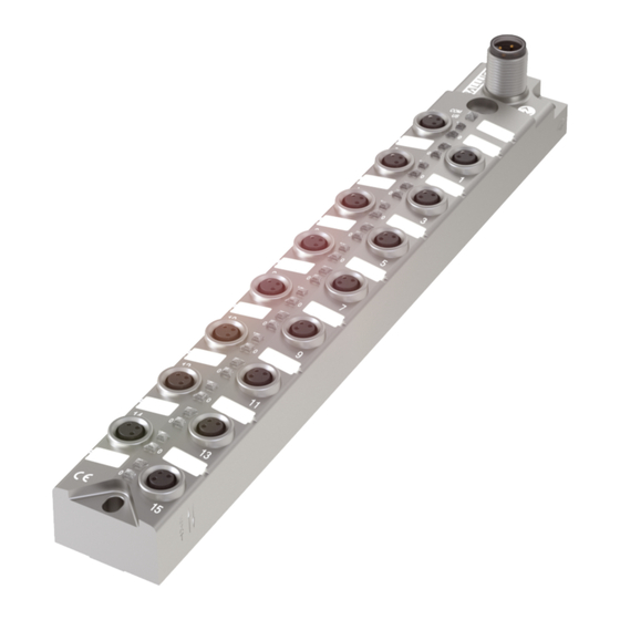
Balluff Network Interface / IO-Link BNI IOL-104-002-Z046 First Steps 3.1. Connection Overview Figure 3-1: Connection overview BNI IOL-104-002-Z046 1 Ground connection 13 Pin/Port LED: signal status 2 Mounting hole 14 Port 14 3 Status LED: communication 15 Port 12 4 Part label... -
Page 7: Mechanical Connection
IO-Link The IO-Link connection is established via an M12 connector (A-coded, male). connection IO-Link (M12, A-coded, male) Requirement Supply voltage controller US, +24V Not used GND, reference potential C/Q, IO-Link data transmission channel www.balluff.com... -
Page 8: Connecting The Sensor Hub
Balluff Network Interface / IO-Link BNI IOL-104-002-Z046 First Steps Connecting the Connect ground conductor to the functional ground connection, if available. sensor hub Connect the incoming IO-Link cable to the sensor hub. Note A standardized sensor cable is used to connect to the higher-level to the IO-Link master module. -
Page 9: General Configuration
4.1. Extension port The BNI IOL-104-002-Z046 module gives you the ability to use the No. 15 slot in various ways. By default it is used as a digital input slot, where Pin 4 can be used as a digital input. -
Page 10: Configuration: "Extension Off
Balluff Network Interface / IO-Link BNI IOL-104-002-Z046 Configuration: "Extension Off" 5.1. IO-Link data BNI IOL-104-002-Z046 Extension port Transmission rate COM2 (38.4 kBaud) Minimum cycle time 3.5 ms Process data length 2-byte input 5.2. Process Byte Data/Input Data www.balluff.com... -
Page 11: Parameter Data / Demand Data
Subin Vendor ID 2 bytes 0378 Device ID 3 bytes 005 0D 40 Vendor Name BALLUFF Vendor text www.balluff.com Product BNI IOL-104-002-Z046 Name Product ID BNI00AY Product text Sensor hub M8 Serial number 16 bytes 0hex Hardware revision Firmware revision... -
Page 12: Inversion Of The Inputs (40Hex)
Balluff Network Interface / IO-Link BNI IOL-104-002-Z046 Configuration: "Extension Off" Inversion of the Byte inputs (40 Subin Inversion of port (x): 0 – Normal 1 - Inverted. Voltage Byte monitoring Sub- Index Byte Sub- Index www.balluff.com... -
Page 13: Configuration: Extended With Bni Iol-104-002-Z046
Configuration: Extended with BNI IOL-104-002-Z046 6.1. IO-Link data BNI IOL-104-002-Z046 extended with BNI IOL-104-002-Z046 Transmission rate COM2 (38.4 kBaud) Minimum cycle time 4.1 ms Process data length 4-byte input 6.2. Process Byte Data/Input Data Byte Extension port www.balluff.com... -
Page 14: Parameter Data / Demand Data
Balluff Network Interface / IO-Link BNI IOL-104-002-Z046 Configuration: Extended with BNI IOL-104-002-Z046 6.3. Parameter Data ISDU Parameter Data Access Default value / Demand Data width rights Index Index Subin Vendor ID 2 bytes 0378 Device ID 3 bytes 05 0D 4... -
Page 15: Inversion Of The Inputs (40Hex)
Configuration: Extended with BNI IOL-104-002-Z046 Inversion of Byte the inputs Sub- Index Byte Sub- Index Extension port Inversion of port (x): 0 - Normal 1 - Inverted www.balluff.com... -
Page 16: Voltage Monitoring 44Hex
Balluff Network Interface / IO-Link BNI IOL-104-002-Z046 Configuration: Extended with BNI IOL-104-002-Z046 Voltage Byte monitoring Sub- Index Byte Sub- Index Byte Sub- Index Extension port www.balluff.com... -
Page 17: Setting The Serial Number 54Hex
Configuration: Extended with BNI IOL-104-002-Z046 Byte Sub- Index Extension port Setting the The serial number has a default value of 16x00 hex. serial number In order to use the "Identity" master validation mode, a serial number can be set using this parameter. -
Page 18: Diagnostics
Balluff Network Interface / IO-Link BNI IOL-104-002-Z046 Diagnostics 7.1. Error Codes/ Error Code Description Errors 0x8011 Index not available 0x8012 Subindex not available 0x8023 Access Denied 0x8033 Parameter length overrun 0x8034 Parameter length underrun 0x8035 Function not available 7.2. Events IO-Link Revision 1.0... -
Page 19: Io-Link Functions
The factory settings on the device can be restored by running the "restore factory settings" Factory system command. Settings 0x82 must be written to Index 2 Subindex 0 for the command. The extension port setting is not reset in this process. www.balluff.com... -
Page 20: Technical Data
Balluff Network Interface / IO-Link BNI IOL-104-002-Z046 Technical Data 9.1. Dimensions 9.2. Mechanical Housing material die-cast zinc, matte nickel-plated Data IO-Link port M12, A-coded, plug Inputs port 16xM8, jack Weight 402 g Dimensions (L×W×H) 30 x 220 x 32.8 (mm) 9.3. -
Page 21: Function Indicators
Function indicators 10.1. Function indicators COM/ LED indicator Status Function module status Green Communication error, US OK Green, flashing Communication OK and US OK Red, flashing quickly Undervoltage module www.balluff.com... -
Page 22: Digital Led Indicators For Inputs/Outputs
Balluff Network Interface / IO-Link BNI IOL-104-002-Z046 Function indicators Digital LED LED 2, Input Pin 4 indicators for Status Function inputs/outputs Input signal = 0 Yellow Input signal = 1 Sensor supply short-circuit Extension port The table is valid if the extension port is active. If the extension port is used as a standard I, then the description from "Digital LED indicators for inputs"... -
Page 23: Appendix
Appendix 11.1. Type code BNI IOL-104-002-Z046 Balluff Network Interface IO-Link interface Functions 104 = 16 inputs Variants 002 = with IO-Link 1.1 extension port Mechanical configuration Z046 = Die-cast zinc, matte nickel plated Bus connection: 1x M12x1 external threads, 16 x M8x1 internal thread 11.2. -
Page 24: Www.balluff.com
Balluff GmbH Schurwaldstrasse 9 73765 Neuhausen a.d.F. Germany Tel. +49 7158 173-0 Fax +49 7158 5010 www.balluff.com balluff@balluff.de...
Need help?
Do you have a question about the BNI IOL-104-002-Z046 and is the answer not in the manual?
Questions and answers