Table of Contents
Advertisement
Quick Links
Advertisement
Table of Contents

Subscribe to Our Youtube Channel
Related Manuals for Balluff BNI IOL-709-000-K006


Summary of Contents for Balluff BNI IOL-709-000-K006
- Page 1 BNI IOL-709-000-K006 BNI IOL-710-000-K006 IO-Link Sensor-Hub analog User’s Guide...
-
Page 2: Table Of Contents
Switch point enable Switch point 4.5 Errors 4.6 Events Technical Data 5.1 Dimensions 5.2 Mechanical data 5.3 Electrical data 5.4 Operating conditions 5.5 Function indicators Module LEDs Digital Input LEDs Analogue Input LEDs Appendix 6.1 Type designation code 6.2 Order information www.balluff.com... -
Page 3: Notes To The User
BNI IOL-709-… / BNI IOL-710-… Notes to the user 1.1 About this guide This guide describes the Balluff IO-Link sensor collector module, also called the Sensor Hub. Connection to the host interface master is made through the IO-Link protocol. Functionally this compact, cost-effective module is comparable with a passive splitter box: It takes digital and analogue sensor signals and passes them over the IO-Link interface. -
Page 4: Safety
Note voltage Disconnect all power before servicing equipment. Note In the interest of product improvement, the Balluff GmbH reserves the right to change the specifications of the product and the contents of this manual at any time without notice. www.balluff.com... -
Page 5: Getting Started
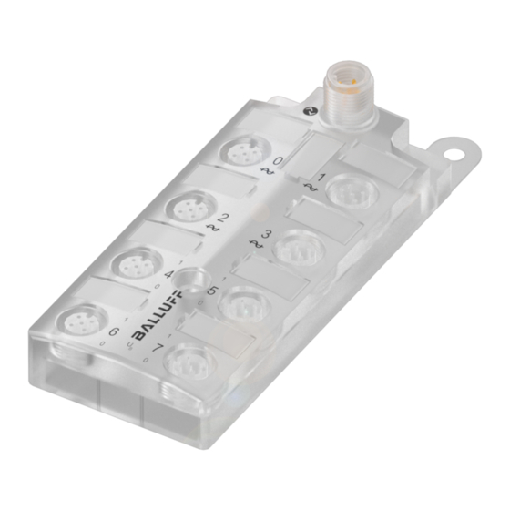
5 Analogue input port 3 14 Analogue input port 0 6 Status-LED: digital input Pin 2 15 Label 16 Status-LED „COM“ 7 Digital input port 1 8 Status-LED: Digital port Pin 4 17 Function ground connection 9 Digital input port 3 www.balluff.com... -
Page 6: Mechanical Connection
GND, reference potential C/Q, IO-Link data transmission channel Connection protection ground to FE terminal, if present. Connect the incoming IO-Link line to the Sensor Hub. Note! A standard sensor cable is used for connecting to the host IO-Link Master. www.balluff.com... -
Page 7: Digital Sensors
+24 V, 100 mA BNI IOL-709...: 4 - 20 mA BNI IOL-710…:n.c. 0 V, GND BNI IOL-710...: 0 - 10 V BNI IOL-709…:n.c FE, function ground Note! Unused I/O port sockets must be fitted with cover caps to ensure IP67 protection rating. www.balluff.com... -
Page 8: Io-Link Interface
Process data length 10Byte: Byte 0 Byte 1 Byte 2 Byte 3 Analogue value Port 0 Byte 4 Byte 5 Analogue value Port 1 Byte 6 Byte 7 Analogue value Port 2 Byte 8 Byte 9 Analogue value Port 3 www.balluff.com... -
Page 9: Process Data Outputs
Vendor text 16 Byte Product Name 34 Byte Product ID 21 Byte Product text 34 Byte Hardware Revision 3 Byte Firmware Revision 3 Byte Identification data Type Device ID Version BNI IOL-710-000-K006 050201hex Voltage version BNI IOL-709-000-K006 050202hex Current version www.balluff.com... -
Page 10: Inversion
Inversion Inversion of the input signals: Byte 0 Byte 1 Switch point Enable the switch points by setting the enable bits enable Byte 0 Switch point Byte 0 Byte 1 Switch point Value range (dec) CV= 400…2000 VV= 0…1000 www.balluff.com... -
Page 11: Errors
Supply low disappears Error supply U2 = supply + 24V Hardware voltage 5000 0100 0010 0002 5112 Device appears Error supply supply periphery Hardware 5000 0100 0060 5160 Device disappears Error supply supply periphery Hardware 5000 0100 0060 5160 www.balluff.com... -
Page 12: Technical Data
Ripple < 1 % ≤ 40 mA Current draw without load -5 °C … +55 °C 5.4 Operating Operating temperature conditions -25 °C … +70 °C Storage temperature Severity level 4A/3A/4B/2A/3A – EN 61000-4-2/3/4/5/6 Vibration/shock EN 60068 part 2-6/27 www.balluff.com... -
Page 13: Function Indicators
Input signal = 0 Analogue Input LED 1, Analogue input port LEDs Status Signal 709 (4-20 mA) Signal 710 (0-10 V) ≥ 4 mA - ≤ 20 mA Green > 0,05 V < 4 mA - > 20 mA > 10,05 V www.balluff.com... -
Page 14: Appendix
Appendix 6.1 Type designation code BNI IOL-7xx-000-K006 Balluff Network Interface IO-Link interface Functions 710 = 8 digital inputs 0,15 A + 4 analog inputs 0 - 10 V 709 = 8 digital inputs 0,15 A + 4 analog inputs 4 - 20 mA... - Page 15 IO-Link Sensor-Hub BNI IOL-709-… / BNI IOL-710-… Notes www.balluff.com...
- Page 16 Balluff GmbH Schurwaldstrasse 9 73765 Neuhausen a.d.F. Germany Tel. +49 7158 173-0 Fax +49 7158 5010 www.balluff.com balluff@balluff.de...
Need help?
Do you have a question about the BNI IOL-709-000-K006 and is the answer not in the manual?
Questions and answers