
Related Manuals for Balluff BNI IOL-309-002-Z019


Summary of Contents for Balluff BNI IOL-309-002-Z019
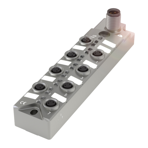
- Page 1 BNI IOL-309-002-Z019 IO-Link 1.1 sensor/actuator hub with extension port User's Guide...
-
Page 2: Table Of Contents
Balluff Network Interface / IO-Link BNI IOL-309-002-Z019 Contents User Instructions 1.1. About This Manual 1.2. Structure of the Manual 1.3. Typographical Conventions Enumerations Actions Syntax Cross-references 1.4. Symbols 1.5. Abbreviations 1.6. Differing views Safety 2.1. Intended use 2.2. Installation and Startup 2.3. - Page 3 Resetting to Factory Settings Technical Data 9.1. Dimensions 9.2. Mechanical Data 9.3. Electrical Data 9.4. Operating conditions Function Indicators 10.1. Function Indicators LED-Indicators module status Digital LED indicators for inputs/outputs Extension port Appendix 11.1. Type Code 11.2. Ordering Information www.balluff.com...
-
Page 4: User Instructions
Balluff Network Interface / IO-Link BNI IOL-309-002-Z019 User Instructions 1.1. About This This manual describes the Balluff IO-Link I/O module, also called a sensor/actuator hub. Manual The IO-Link protocol is used to link to the higher-level master module. In terms of function, this compact, cost-effective module is similar to a passive splitter box; it records digital and analog sensor signals and transmits them over the IO-Link interface. -
Page 5: Safety
Before maintenance, disconnect the device from the power supply. Note In the interests of product improvement, Balluff GmbH reserves the right to change the technical data of the product and the content of this manual at any time without notice. -
Page 6: First Steps
Balluff Network Interface / IO-Link BNI IOL-309-002-Z019 First Steps 3.1. Connection Overview Figure 3-1: Connection overview BNI IOL-309-002-Z019 1 Ground connection 8 Port 7, extension port 2 Mounting hole 9 Pin/Port LED: signal status 3 Status LED: communication 10 Port 6... -
Page 7: Mechanical Connection
The BNI IOL modules are attached using 2 max. M4 screws and 2 washers. Connection 3.3. Electrical The BNI IOL-309-002-Z019 modules do not require a separate supply voltage connection. Connection Supply voltage is provided via the IO-Link interface and the higher-level IO-Link master module. -
Page 8: Connecting The Sensor Hub
Balluff Network Interface / IO-Link BNI IOL-309-002-Z019 First Steps Connect ground conductor to the functional ground connection, if available. Connecting the Connect the incoming IO-Link cable to the sensor hub. sensor hub Note A standardized sensor cable is used to connect to the higher-level IO-Link master module. -
Page 9: General Configuration
4.1. Extension port The BNI IOL-309-002-Z019 module gives you the ability to use the No. 7 slot in various ways. By default, it is used as a digital I/O slot, where pin 4 can be used as a digital input or output. -
Page 10: Configuration: "Extension Off
Balluff Network Interface / IO-Link BNI IOL-309-002-Z019 Configuration: "Extension Off" 5.1. IO-Link Data BNI IOL-309-002-Z019 extension off Transmission rate COM2 (38.4 kbaud) Minimum cycle time 3.5 ms Process data length 1 byte input, 1 byte output 5.2. Process Data Byte Input 5.3. -
Page 11: Parameter Data/Demand Data
Device ID 3 bytes 0x05 0B 10 Vendor name 8 bytes BALLUFF Vendor text 16 bytes www.balluff.com Product 20/24 BNI IOL-309-002-Z019 name bytes Product ID 7 bytes BNI0093 Product text 16 bytes sensor/actuator hub M8 Serial number 16 bytes Hardware... -
Page 12: Hex
Balluff Network Interface / IO-Link BNI IOL-309-002-Z019 Configuration: "Extension Off" Inversion of the Byte inputs 40 Sub- index Inversion port (x): 0 – Normal 1 – Inverted. Configuration Byte In-Outputs 41 Index Direction port (x): 0 – Input 1 – Output Safe state of The safe state parameter makes it possible to configure the outputs in case of a fault. - Page 13 Configuration: "Extension Off" Value Output state Output is 0V Output is 24V Current status is maintained Not defined www.balluff.com...
-
Page 14: Hex
Balluff Network Interface / IO-Link BNI IOL-309-002-Z019 Configuration: "Extension Off" Voltage Byte monitoring Sub- index Monitoring Byte the outputs Sub- index www.balluff.com... -
Page 15: Configuration: Extended With Bni Iol-102-002-Z019
Configuration: extended with BNI IOL-102-002-Z019 6.1. IO-Link Data BNI IOL-309-002-Z019 extended with BNI IOL-102-002-Z019 Transmission rate COM2 (38.4 kbaud) Minimum cycle time 4.0 ms Process data length 2 byte input, 1 byte output 6.2. Process Byte Data/Input Data Byte Extension port... -
Page 16: Process Data/ Output Data
Balluff Network Interface / IO-Link BNI IOL-309-002-Z019 Configuration: extended with BNI IOL-102-002-Z019 6.3. Process Data/ Byte Output Data www.balluff.com... -
Page 17: Parameter Data/Demand Data
2 bytes 0378 Device ID 3 bytes 0x05 0B A1 Vendor name 8 bytes BALLUFF Vendor text 16 bytes www.balluff.com BNI IOL-309-002-Z019 Product 20/24 with BNI IOL-102-002- name bytes Z019 Product ID 7 bytes BNI0093 with BNI0099 M12 sensor/actuator Product text... -
Page 18: Hex
Balluff Network Interface / IO-Link BNI IOL-309-002-Z019 Configuration: extended with BNI IOL-102-002-Z019 Inversion of the Byte inputs 40 Sub- index Byte Sub- index Extension port Inversion port (x): 0 - Normal 1 - Inverted Configuration Byte In-/Output Index www.balluff.com... -
Page 19: Safe State Of Outputs
The following statuses can be configured for each pin. Safe state of Byte the outputs on Pin 4 42 Sub- index Value Output state Output is 0V Output is 24V Current status is maintained Not permitted www.balluff.com... -
Page 20: Voltage Monitoring
Balluff Network Interface / IO-Link BNI IOL-309-002-Z019 Configuration: extended with BNI IOL-102-002-Z019 Voltage Byte monitoring Sub- index Byte Sub- index Extension port Monitoring the Byte outputs 45 Sub- index Setting the The serial number has a default value of 16x00 serial number In order to use the "Identity"... -
Page 21: Diagnosis
IO-Link Revision 1.1 Event code Description 0x5111 Low sensor voltage (US) 0x5112 Low actuator voltage (UA) 0x7710 Short circuit 0x8DF0 Retry at the extension port 0x8DF1 Device lost at the extension port 0x8DF2 Wrong device at the extension port www.balluff.com... -
Page 22: Io-Link Functions
Balluff Network Interface / IO-Link BNI IOL-309-002-Z019 IO-Link Functions 8.1. IO-Link This device can be operated with an IO-Link master according to IO-Link version 1.0 and Version 1.0 / version 1.1. Version-specific functions such as data storage (version 1.1) are only supported in combination with a suitable IO-Link master. -
Page 23: Technical Data
Load current per output (PIN 4) max. 300 mA (temperature-dependent) Inputs PNP, type 3 9.4. Operating Ambient temperature - 5 °C … +70 °C conditions Storage temperature - 25 °C … +70 °C IP67 (only in plugged-in and screwed Degree of protection state) www.balluff.com... -
Page 24: Function Indicators
Balluff Network Interface / IO-Link BNI IOL-309-002-Z019 Function Indicators 10.1. Function Indicators COM/ US/UA LED-Indicators Status Function module status Green Communication error Green flashing Communication ok US/UA Undervoltage actuator Red fast flashing Undervoltage module www.balluff.com... -
Page 25: Digital Led Indicators For Inputs/Outputs
"Digital LED indicators for inputs/outputs" can be used. Status Function Green IO-Link – connection active Green flashing No IO-Link connection or faulty IO-Link device Red flashing Incorrect IO-Link device or incorrect configuration IO-Link short-circuit on Pin 4 www.balluff.com... -
Page 26: Appendix
Balluff Network Interface / IO-Link BNI IOL-309-002-Z019 Appendix 11.1. Type Code BNI IOL-309-002-Z019 Balluff Network Interface IO-Link interface Functions 309= 8 inputs/outputs Variants 002 = with IO-Link 1.1 extension port Mechanical configuration Z019 = Die-cast zinc housing, matte nickel plated... - Page 27 Notes www.balluff.com...
- Page 28 Balluff GmbH Schurwaldstrasse 9 73765 Neuhausen a.d.F. Germany Phone +49 7158 173-0 Fax +49 7158 5010 www.balluff.com balluff@balluff.de...
Need help?
Do you have a question about the BNI IOL-309-002-Z019 and is the answer not in the manual?
Questions and answers