
Related Manuals for Balluff BNI IOL-101-000-K018


Summary of Contents for Balluff BNI IOL-101-000-K018
- Page 1 BNI IOL-101-000-K018 BNI IOL-102-000-K019 BNI IOL-101-S01-K018 BNI IOL-102-S01-K019 User´s Guide...
-
Page 2: Table Of Contents
Module versions Sensorinterface IO-Link interface 4.1. IO-Link data 4.2. Process data / Output data 4.3. Process data / Input data BNI IOL-101-000-K018 BNI IOL-102-000-K019 BNI IOL-101-S01-K018 BNI IOL-102-S01-K019 4.4. Parameter data/ Request data Inversion of the inputs 40hex 4.5. Errors 4.6. -
Page 3: Notes
Balluff Network Interface / IO-Link Notes 1.1. Struture of the The guide is organized so that the sections build on one another. guide Section 2: Basic safety information. ……. 1.2. Typographical The following typographical conventions are used in this guide. -
Page 4: Safety
Safety 2.1. Intended use This guide describes the Balluff IO-Link sensor collector module, also called Sensor Hub. Connection to the host interface master is made through the IO-Link protocol. Functionally this compact, cost-effective module is comparable with a passive splitter box: It takes conventional sensor signals and passes them over the IO-Link interface. -
Page 5: Getting Started
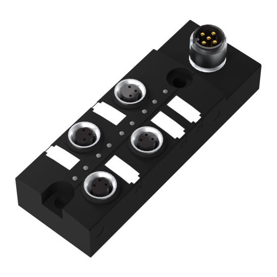
Balluff Network Interface / IO-Link Getting started 3.1. Connection overview 8 port module Figure 3-1: BNI IOL-102-000-K019 / BNI IOL-102-S01-K019 1 IO-Link interface 8 Mounting hole 2 Mounting hole 9 Port LED: Standard input port 7, Pin 4 3 Status LED: Communication / module... -
Page 6: Connection Overview 4 Port Module
3 Status LED: Communication / module 4 Standard input port 1 5 Standard input port 3 6 Mounting hole 7 Port LED: Standard input port 3 Pin 4 8 Standard input port 2 9 Label 10 Standard input port 0 www.balluff.com... -
Page 7: Mechanical Connection
Balluff Network Interface / IO-Link Getting started 3.3. Mechanical The Module BNI IOL … modules are attached by using 2 M4 screws and 2 spacers. connection 3.4. Electrical The sensor hub modules require no separate supply voltage connection. Power is provided connection through the IO-Link interface by the host IO-Link master. -
Page 8: Io-Link Interface
IO-Link interface 4.1. IO-Link data BNI IOL-101-000-K018 / BNI IOL-102-000-K019 Data transmission rate COM2 (38,4 kBaud) Frame type Minimal cycle time 2.5 ms Process data cycle time 2.5 ms, at minimal cycle time Process data length 1 Byte BNI IOL-101-S01-K018 / BNI IOL-102-S01-K019... -
Page 9: Process Data / Input Data
Balluff Network Interface / IO-Link IO-Link interface 4.3. Process data / Input data BNI IOL-101-000- 4 binary inputs K018 Byte BNI IOL-102-000- 8 binary inputs K019 Byte www.balluff.com... -
Page 10: Bni Iol-101-S01-K018
IO-Link interface BNI IOL-101-S01- 4 binary inputs with single channel monitoring K018 Byte BNI IOL-102-S01- 8 binary inputs with single channel monitoring K019 Byte www.balluff.com... -
Page 11: Parameter Data/Request Data
Sensor hub digital M8 8 inputs SPC Hardware 1 Byte Revision Firmware 23 Byte Revision SPDU Default Object name Length Range Index Index Sub- value index Inversion 1 Byte 0-FF Inversion of the Byte inputs 40 *not used at BNI IOL-101-000-K018 www.balluff.com... -
Page 12: Errors
0x80 0x30 0x03 0x5000 0x0100 0x0010 0x0002 0xB3 0x5112 Device Appears Error Supply Supply periphery Hardware 0xC0 0x30 0x03 0x5000 0x0100 0x0060 0xF3 0x5160 Device Disappears Error Supply Supply periphery Hardware 0x80 0x30 0x03 0x5000 0x0100 0x0060 0xB3 0x5160 www.balluff.com... -
Page 13: Technical Data
Balluff Network Interface / IO-Link Technical Data 5.1. Dimensions Figure 5-1: BNI IOL-101-xxx-K018 Figure 5-2: BNI IOL-102-xxx-K019 5.2. Mechanical data Housing material Plastic IO-Link port M12, A-coded, male I-ports M8, female, 3-pole Enclosure rating per IEC 60529 IP 67 (only when plugged and threaded in) -
Page 14: Led Indicators
LED 2 LED 1 Figure 5-3: LED indicators Module status LED 2, Communication / module supply Indication Function Green No communication, supply ok Green, negative LED 2 Communication ok, supply ok pulsed Red, flashing Communiction fault, supply undervoltage / overload www.balluff.com... -
Page 15: Led I-Ports Standard
Balluff Network Interface / IO-Link Technical Data LED I-ports BNI IOL-101-000-K018 / BNI IOL-102-000-K019 Standard LED 1, I-Port Pin 4 Indication Function Yellow, static Input signal = 1 Input signal = 0 LED I-ports with BNI IOL-101-S01-K018 / BNI IOL-102-S01-K019... -
Page 16: Appendix
Appendix 6.1. Product ordering BNI IOL-10x-x0x-K01x code Balluff Network Interface IO-Link Interface Function 101 = 4-Port 102 = 8-Port Variants 000 = Standard version S01 = with single channel monitoring Mechanical version K018 = Plastic housing, M8, 4 port IO-Link interface and power supply: 1xM12 external thread... -
Page 17: Notes
Balluff Network Interface / IO-Link Notes www.balluff.com... - Page 18 Balluff GmbH Schurwaldstrasse 9 73765 Neuhausen a.d.F. Deutschland Tel. +49 7158 173-0 Fax +49 7158 5010 www.balluff.com balluff@balluff.de...
Need help?
Do you have a question about the BNI IOL-101-000-K018 and is the answer not in the manual?
Questions and answers