Table of Contents
Advertisement
Quick Links
Advertisement
Chapters
Table of Contents

Related Manuals for Launch STS600


Summary of Contents for Launch STS600
- Page 1 User’s Manual English STS600 Sensor Tester & Simulator User’s Manual...
- Page 2 LAUNCH. The information contained herein is designed only for the use of this unit. LAUNCH is not responsible for any use of this information as applied to other units.
- Page 3 LAUNCH STS600 Neither LAUNCH nor its affiliates shall be liable to the purchaser of this unit or third parties for damages, losses, costs, or expenses incurred by purchaser or third parties as a result of: accident, misuse, or abuse of this unit, or...
-
Page 4: Table Of Contents
LAUNCH STS600 Table of Contents 1. CAUTION .................E-2 2. GENERAL................E-2 3. MAJOR FUNCTIONS ............E-3 4. STRUCTURE ..............E-4 5. OPERATION INSTRUCTION ..........E-5 5.1 NOTES ...............E-5 5.2 POWER ..............E-6 5.3 SCREEN..............E-6 5.4 KEYBOARD OPERATION ...........E-7 5.5 VOLTAGE MEASUREMENT ........E-9 5.6 RESISTANCE MEASUREMENT ........ E-10 5.7 FREQUENCY MEASUREMENT ........ -
Page 5: Caution
1.3 If there is any quality problem with this unit during one year warranty (starting from the date of the invoice), please contact the nearest distributor or LAUNCH,free service will be offered if such a problem is not resulting from unauthorized service. - Page 6 LAUNCH STS600 3. MAJOR FEATURES Big character LCD, 3-digital display of measure, maximum and minimum along with unit indication and icons for test functions Anti-dirt film keyboard Automatic range selection for voltage and resistance measure Measure precision less than 1% FSR Response time <1S...
-
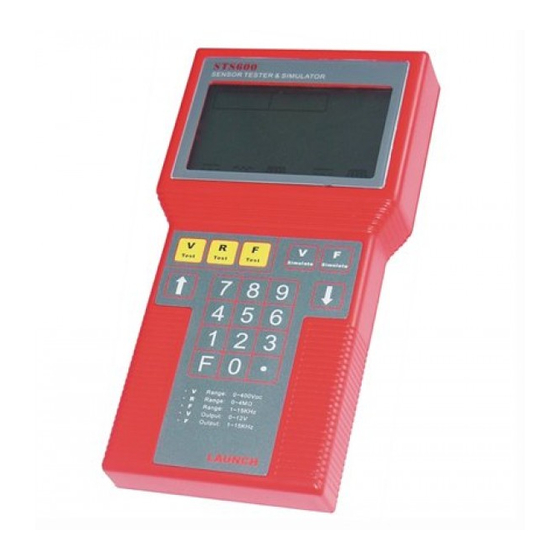
Page 7: Structure
LAUNCH STS600 4. STRUCTURE Fig.1 STS600 ①Display window;②Keyboard;③Power cable;④Measure plug;⑤Power plug;⑥Test cable. The instrument mainly consists of two parts: the meter and the external cables. The external cables are signal cables... -
Page 8: Operation Instruction
LAUNCH STS600 (⑥ of Fig.1)and power cable(③ of Fig.1).The signal cables can be connected to the meter through a DB9 plug. The power cable is linked to the meter by a 2-pin plug. The instrument front surface is divided into two parts: LCD display window on the upper part (①... -
Page 9: Power
LAUNCH STS600 5.2 POWER After correctly connecting the power cable to the two poles of auto battery (12V), the instrument will start self-testing. The screen will show all the characters (see Fig.2). You would hear one ‘bee’ sound confirming the instrument in normal condition. -
Page 10: Keyboard Operation
LAUNCH STS600 Fig.2 Full display 5.4 KEYBOARD OPERATION 5.4.1 keyboard layout See Fig.3, there are 19 keys in total. - Page 11 LAUNCH STS600 Fig3 Keyboard layout Five main function keys from left to right correspond to five main function icons on the screen separately as Voltage test key, Resistance test key, Frequency test key, Voltage simulation key (λ O sensor simulation key) and Frequency simulation key.
-
Page 12: Voltage Measurement
LAUNCH STS600 Three additional function keys: Keys ‘↑’ and ’↓’ are used for continuous increasing or decreasing adjustment of simulation value. Key ‘F’ is an additional key for combined keys use. Digit keys (0--9) and decimal key: They are only used for setting parameter of frequency simulation and voltage simulation. -
Page 13: Resistance Measurement
LAUNCH STS600 also shown by the dynamic bar. The value out of 40V will make the dynamic bar reach its full length. For example, the screen of 20V DC measuring is like Fig.5. Fig.5 The display when measuring 20V DC If the voltage value goes beyond 400V, it should be displayed mark ‘1.’. - Page 14 LAUNCH STS600 Fig.6 Initial display when ‘resistance measurement’ is pressed After the signal jaws to the measure points be connected, resistance value will be shown. The testing max. and min. value will simultaneously be displayed on the upper section. For example, if measured resistance is 1.5Ω, it will display like Fig.7.
-
Page 15: Frequency Measurement
LAUNCH STS600 Fig.7 The display when measured resistance is 1.5KΩ If signal jaws are disconnected at this moment or the resistance value goes beyond 4M Ω , the mark ‘1.’ for over-range will be displayed. There are three range of measured resistance values: Ω、... - Page 16 LAUNCH STS600 Connecting the signal jaws to the measurement points, it will show the frequency value. The max. and min. testing values will simultaneously be shown on the upper part of the screen. For example, the screen will be like Fig.9 when measuring 1Hz.
-
Page 17: Frequency Simulation
LAUNCH STS600 Fig.10 the displayed mark for over-range Refer to the corresponding description in ‘resistance measurement’ for max. and min. value meanings. 5.8 FREQUENCY SIMULATION 5.8.1 Operation procedure 1) It enters the status of setting parameter for frequency simulation after pressing ‘frequency simulation’ key. The ‘frequency simulation’... - Page 18 LAUNCH STS600 Note: The delete function only used in the status of parameter setting. Fig.11 the display of setting parameter If you don't input any number or the number of input isn’t in the range from 1Hz to 15kHz, then pressing ‘frequency measurement’...
- Page 19 LAUNCH STS600 finished the parameter setting. Now you can press ‘frequency simulation’ key to output the signal of frequency simulation. If the parameter is correct, it should output the corresponding signal of frequency simulation, at the same time the ‘Min.’ display ‘-- -- --’. It indicated that it had entered the status of frequency simulation.
-
Page 20: O2 Sensor Simulation
LAUNCH STS600 If the current frequency unit is ‘KHz’ and the display number in the range from 1KHz to 10KHz, each press ‘↑’ or ‘↓’ key would add or subtract 0.01KHz. If the current frequency unit is ‘KHz’ and the display number in the range from 10KHz to 15KHz, each press ‘↑’... - Page 21 LAUNCH STS600 Fig.13 the display of max. voltage The min. voltage displays as shown in Fig14. Fig.14 the display of min. voltage E-18...
-
Page 22: Voltage Simulation
LAUNCH STS600 5.10 VOLTAGE SIMULATION 5.10.1 Operation procedure 1) It enters the status of setting parameter for voltage simulation after pressing ‘voltage simulation’ key. The ‘voltage simulation’ selection icons and voltage unit ‘V’ will be lit (see Fig.15). Fig.15 initial display for ‘voltage simulation’... - Page 23 LAUNCH STS600 Fig.16 the display when entering “11.5V” If you don’t input any number or the number of input isn’t in the range of 0V~12V, then pressing ‘voltage measurement’ function key will cause ‘Err’ character on the screen and respond three sounds to remind user to input number. At last it returns to the Fig.11 for input again.
-
Page 24: Faq
LAUNCH STS600 If the number is integer or decimals, each time the scope of adjustment is ±0.1V. 6. FAQ If the instrument fails to work normally due to accidents, it can be restarted by disconnecting power, and then power-on again . - Page 25 The exclusive remedy for any automotive meter found to be defective is repair or replacement, and LAUNCH shall not be liable for consequential incidental damages.
- Page 26 Send the unit pre-paid to: Attn: Overseas Department LAUNCH TECH. CO., LTD. Xinyang Building, Bagua 4th Road, Shenzhen, Guangdong Province, 518029...
- Page 27 说明书 中文 STS600 汽车传感器测试/模拟仪 使用说明书...
- Page 28 元征公司 STS600 使用说明书 版权所有!未征得深圳市元征科技股份有限公司(下称 “元征公 司” )的书面同意,任何公司或个人不得以任何形式(电子、机 械、影印、录制或其它形式)对本说明书进行复制和备份。本手 册专为元征产品的使用而设计, 对于将之用于指导其它设备操作 而导致的各种后果,本公司不承担任何责任。 因使用者个人或第三方的意外事故,滥用、误用该设备,擅自更 改、 修理该设备, 或未按元征公司的操作与保养要求而致使设备 损坏、 遗失所产生的费用及开支等, 元征公司及其分支机构不承 担任何责任。 对于使用其它选用配件或损耗品而非元征公司原装产品或元征 公司认可之产品而导致该设备损坏或出现问题, 元征公司不承担 任何责任。 正式声明: 本说明书所提及之其它产品名称, 目的在于说明该设 备如何使用,其注册商标所有权仍属原公司。 本设备供专业技术人员或维修人员使用。 注册商标 元征公司已在中国及海外若干国家进行了商标注册,其标志为 。本手册所提及之元征公司其它商标,服务标志,域 名,图标,公司名称均属元征公司及其下属公司之产权。在元征 公司之商标, 服务标志, 域名, 图标, 公司名称还未注册之国家, 元征公司声明其对未注册商标,服务标志,域名,图标,公司名 称之所有权。 本手册所提及之其它产品及公司名称的商标仍属于...
- Page 29 元征公司 STS600 使用说明书 目 录 1.注意事项 ............... C-2 2.概述 ................C-2 3.主要性能 ............... C-2 4.主要结构 ............... C-4 5.使用说明 ............... C-5 5.1 注意事项..............C-5 5.2 加电................C-5 5.3 显示屏 ..............C-6 5.4 键盘操作..............C-6 5.5 电压测量..............C-8 5.6 电阻测量 ..............C-9 5.7 频率测量..............
-
Page 30: 1.注意事项
元征公司 STS600 使用说明书 1.注意事项 1.1 用户在使用前务必仔细阅读本说明书, 以免因操作不当造成 仪表损坏。 1.2 打开包装盒后,请核对所有物件是否与包装清单相符。 1.3 本仪表的保修期为一年(以购货发票为准) 。在此期间,若 有质量问题, 请与销售商或本公司联系, 我们将提供免费维 修。在保修期内,请勿私自拆卸本仪表,否则,我公司不予 免费修理。 2.概述 本使用说明书提供了“STS600 汽车传感器测试/模拟仪”性能 和使用方面的详细资料。 “STS600 汽车传感器测试/模拟仪”系智能型测试仪表,具有 加电自检和自动量程转换功能。 主要用于检测各种汽车传感器的 工作状态是否正常(通过测试电压、电阻和频率) ,并能模拟传 感器产生输出信号(电压、频率和 λ 氧传感器信号) 。 3.主要性能 大字符液晶显示器显示,3 位数字测量值、最大值和最小值 显示。单位指示和测试功能的图标指示 防污薄膜按键 电压、电阻测量时自动量程切换 测试精度优于 1% FSR 测试时间<1S... - Page 31 元征公司 STS600 使用说明书 11) λ 氧传感器信号(高电压:1V;低电压:0V) 12) 电源电压:直流 12V(汽车电瓶) 13) 环境温度:-5℃~+50℃ 14) 环境湿度:0%RH~85%RH 15) 静态电源电流:≤70mA 16) 体积:320X166X40 mm 17) 重量:486 克...
-
Page 32: 4.主要结构
元征公司 STS600 使用说明书 4.主要结构 仪表外形如图 1 图 1 仪表外形图... -
Page 33: 5.使用说明
元征公司 STS600 使用说明书 ①显示屏 ②键盘 ③电源线 ④测试线插头 ⑤电源线插头 ⑥测试线 仪表主要可分为两部分:表体和外接线。外接线包括测试线(图 1 中的⑥)和电源线(图 1 中的③) 。测试线通过一个 DB9 型插 件与表体连接。电源线通过一个二芯插件与表体连接。 仪表表面由两部分组成:上部分为液晶显示屏(图 1 中的①所 示) ,下部为键盘(图 1 中②的所示) 。 5.使用说明 5.1 注意事项 在图 1 中,仪表的顶端有两个插座,右边为测试线插座,左边 为电源线插座。 使用时, 分别把测试线和电源线插头插入相应的 插座。电源线有红黑两夹。红夹接电源正极,黑夹则接负极。测 试夹也有红、黑两夹。黑夹是信号公共端(信号地线) ;红夹是 电压、电阻、频率测试输入端和模拟电压、模拟频率及 λ 氧传感... -
Page 34: 显示屏
元征公司 STS600 使用说明书 表明仪表自检正常,然后仪器进入监控状态,显示屏显示“P” 字样,等待用户选择六种功能。 5.3 显示屏 见图 2,各部分意义如下: 显示测量过程出现的最大值(仅对电压测试、电阻测试和频 率测试有效) 显示测量过程出现的最小值(仅对电压测试、电阻测试和频 率测试有效) 显示测量值或键入值 单位显示区(根据档位的不同,显示相应的单位) 动态显示条, 通过水平光标长度的变化指示电压值大小 (仅 电压测量时有效) 测量和模拟主功能图标,从左到右分别是:电压测试、电 阻测试、频率测试、电压模拟、频率模拟。注意,五个矩 形框中的图形是常有的。当某一图标外框点亮,表示该功 能正被使用。 图 2 显示屏全显示 5.4 键盘操作 5.4.1 键盘分布 如图 3 所示,共有 19 键。... - Page 35 元征公司 STS600 使用说明书 图 3 键盘分布图 五个主功能键,与屏幕上的五个主功能图标相对应,从左 到右分别是:电压测试、电阻测试、频率测试、电压模拟、 (λ 氧传感器信号模拟)、频率模拟。 注意:对于 λ 氧传感器信号模拟,先按下“F”键不放,然后再 按下电压模拟键,即可进入 λ 氧传感器信号模拟主功能。 三个附加功能键:[↑]、[↓]键用来增减模拟的电压及频率值。 “F”键用作复用功能键。...
-
Page 36: 电压测量
元征公司 STS600 使用说明书 数字键(0--9)和小数点键:这些键仅在电压和频率模拟功能 的设定状态下起作用。 5.4.2 无论当前处于何种状态,只要按下五个主功能键之一,或 者按下“F”键不放,然后按“电压模拟”键(对于 λ 氧传感器模 拟功能) ,都可以立即转入所选的功能。 5.5 电压测量 按下“电压测试”功能键, 这时显示屏上将出现“电压测试”的 图标选择框和电压单位“V”,此时若测试夹悬空,将如图 4 所 示。 图 4 测试夹悬空时的显示 把测试夹接到待测电压两端, 即有测量值显示, 在显示屏上方同 时记录了电压测试过程中出现的最大值和最小值。在 0-40V 的 范围内,有动态显示条对应显示,超过 40V 时动态显示条全显 示。例如,实测一个 20V 直流电压,显示屏显示见图 5。... -
Page 37: 电阻测量
元征公司 STS600 使用说明书 图 5 实测 20V 电压时的显示 超过本仪表电压测试范围 400V 时,屏幕将显示过量程标志 “1.”。 5.6 电阻测量 按下“电阻测试”键, 这时显示屏上将出现“电阻测试”的图标 选择框和电阻单位“Ω”,由于有自动换档过程,稍后几秒钟才 显示所测电阻值。见图 6。 图 6 进入“电阻测试”状态时的显示... -
Page 38: 频率测量
元征公司 STS600 使用说明书 将测试夹接到被测电阻上, 即有测量值显示, 在显示屏上方同时 记录了电阻测试过程中出现的最大和最小值。 例如, 被测电阻为 1.5KΩ,显示状态如图 7 所示。 图 7 实测 1.5KΩ 电阻时的显示 超过 4MΩ,显示过量程标志“1.”,若测试夹悬空,也将显示 过量程标志“1.”。 电阻测量在整个量程范围内经过 Ω、KΩ、MΩ 三个单位。对于 阻值变化很大的电阻, “最大值”和“最小值”有可能不能同时 在同一单位下显示,对于无法表示的最大值或最小值,则显示 “— — —”,但其数值在微电脑中仍然存储。 注意:电阻值越大,由于内部自动量程转换需要较长时间,因而 数字更新越慢。 5.7 频率测量 按下“频率测试”键, 这时显示屏上将出现“频率测试”的图标 选择框和频率单位“Hz”,见图 8。 若此时测试夹悬空,显示状态如图 8。 C-10... - Page 39 元征公司 STS600 使用说明书 将测试夹接至被测频率点, 即有测量值显示, 在显示屏上方同时 记录了频率测量过程中出现的最大值和最小值。 例如, 被测频率 为 1KHz,显示如图 9。 图 8 进入“频率测试”状态时的显示 图 9 1KHz 频率实测时的显示 超过 15KHz,显示过量程标志“1.”, 见图 10。 C-11...
-
Page 40: 频率模拟
元征公司 STS600 使用说明书 图 10 显示的过量程标志 最大值与最小值的显示含义参考电阻测量时的相应说明。 5.8 频率模拟 5.8.1 操作步骤 按下“频率模拟”键,这时进入频率模拟参数设定状态, 显示屏上将出现“频率模拟”的图标选择框和频率单位 “Hz”,见图 11。 此时可进行频率设定,每输入一个数字,显示屏中的数字 左移一位,可输入至小数点后 2 位,若需删除所输入的参 数,先按下“F”键不放,然后按小数点“.”,并释放,则 完成删除功能,可重新进行设定。 注意:删除功能仅在参数设定状态时起作用。 C-12... - Page 41 元征公司 STS600 使用说明书 图 11 进入“频率模拟”设定状态时的显示 若未输入任意数字,再按下“频率模拟”键,则显示屏显示 “Err”字样,并响三声,提示应先输入参数,然后重新返回图 11 状态。 若输入的参数不在 1Hz~15KHz 范围内,当再次按下“频率模 拟”键进行模拟输出时, 则显示屏显示“Err”字样, 并响三声, 提示输入的参数非法,然后重新返回图 11 状态。 3)模拟频率信号的幅值和单位的选择(即:F 键在频率设定中 的使用) 。输出的频率信号有四种组合状态: 5V 幅值、Hz 单位 a. 12V 幅值、Hz 单位 b. 5V 幅值、KHz 单位 c. 12V 幅值、KHz 单位 d. 在本仪器中缺省选择是 a 项,即每次进入参数设定图 11 状态。...
- Page 42 元征公司 STS600 使用说明书 4)频率模拟输出 通过 2) 、3)两种参数的设定方式,即可完成参数设定过程,此 时可通过再按下“频率模拟”键来输出频率信号。若参数合法, 则输出相应的频率信号,此时最小值项显示“— — —”,表示 已进入频率模拟状态,若参数非法,则显示前述“Err”,并重 新进入参数设定状态。 例如:当前模拟频率输出状态为 5V,10.5KHz。见图 12。 图 12 输入“频率模拟”值“5V、10.5KHz”时的显示 5)频率的动态模拟 进入频率输出模拟状态后,可通过一直按下[↑]、[↓]键来动态改 变输出频率。 注意:[↑]、[↓]键仅在模拟运行状态时起作用。 当显示屏显示 Hz 时,每次递增、减数值为 1.00Hz。 当显示屏显示 KHz 时, 并且显示数字在 1KHz~10KHz 范围内时, 每次递增、减数值为 0.01KHz。 当显示屏显示 KHz 时, 并且显示数字在 10KHz~15KHz 范围内...
-
Page 43: Λ 氧传感器信号模拟
元征公司 STS600 使用说明书 5.9 λ 氧传感器信号模拟 按下“F”键不放,然后再按下电压模拟键,即可进入 λ 氧传感 器信号模拟功能。高电压为 1V,低电压为 0V。 高电压为 1V 和低电压为 0V 保持时间为 1-2.5 秒中的随机数, 屏幕显示为如图 13。低电压输出状态为如图 14。每次高→低、 低→高转变,都有声响提示。 图 13 高电压输出显示 C-15... -
Page 44: 电压模拟
元征公司 STS600 使用说明书 图 14 低电压输出显示 5.10 电压模拟 5.10.1 操作步骤 1)按下“电压模拟”键,这时显示屏上将出现“电压模拟”的 图标选择框和电压单位“V”,此时进入电压模拟参数设定状 态,见图 15。 图 15 电压模拟参数设定状态显示 2)输入所需模拟的电压值。每次输入一位数字,显示屏中数字 C-16... - Page 45 元征公司 STS600 使用说明书 将左移一位,如要输入 11.5V,则应顺序输入“11.5”。 在输 入过程中,若要删除所输入的数字,先按下“F”键不放,然后 按小数点“.”键, 即可重新进入图 15 状态。 删除功能仅在参数 设定状态时起作用,模拟输出不起作用。 3)最后,再按下“电压模拟”键,进入电压模拟输出状态。此 时显示屏显示如图 16。 图 16 “电压模拟”值“11.5V”时的显示 若输入的电压设定值不在 0~12V 范围内,将显示“Err” ,并响 三声,提示所输入的参数为非法数字,并且重新返回到图 15 状 态。 若在图 15 状态未输入任何数字,并再次按下“电压模拟”键, 则会同样出现上述提示,要求先输入参数,方可再按下 “电压模 拟”键。 4)电压模拟信号的动态调节 在电压模拟输出状态时, 有两种方法来实现电压模拟信号的动态 输出。 动态跳变调节:若将 11.5V 立即转变为 5V 输出,则在图...
-
Page 46: 6.常见故障处理
元征公司 STS600 使用说明书 动态连续调节:一直按下[↑]或[↓]键,来实现动态连续模拟。 如果显示的参数为小数点后 2 位,如 9.11V,动态连续调节 时,每次调节量为±0.01V。 如果显示的参数为整数或小数点后 1 位,则动态连续调节 时,每次调节量为±0.1V。 6.常见故障处理 1) 由于意外的干扰导致仪表不能正常工作(死机)时,可断开 电源重新加电,仪表便可重新启动,正常工作。 C-18... - Page 47 元征公司 STS600 使用说明书 保修条款 该保修条款仅适用于通过正常程序购买元征公司产品之用户及 经销商。 从交货之日起三年内, 元征公司对其电子产品因材料或工艺缺陷 而造成的损坏进行保修,因滥用、擅自更改、用于非本产品设计 之用途、 未按说明书规定的方式操作等导致本设备或部件损坏不 在本保修范围内。 因本设备缺陷而造成的汽车仪表损坏的赔偿方 式仅限于维修或更换, 元征公司不承担任何间接和偶然损失。 元 征公司将按照其规定的检验方式来判断设备损坏之属性。 元征公 司的任何代理商、 员工及商务代表均无权作出任何与元征公司产 品相关的确认、提示或承诺。 放弃声明 上述保修条款可以代替其它任何形式的保修条款。 订货通知 可更换之零部件和可选配件可直接向元征公司授权的供应商订 购,订货时请注明: 订购数量 零件编号 零件名称 客户服务中心 设备操作过程中遇到任何问题,请致电:86-755-82401306 或 86-755-82269604。 设备需要维修时, 请寄至元征公司, 并附上保修卡、 产品合格证、 购买发票及问题说明。 若设备在保修范围之内, 元征公司将免费...
- Page 48 元征公司 STS600 使用说明书 科技股份有限公司 客户服务中心收 邮政编码:518029...
Need help?
Do you have a question about the STS600 and is the answer not in the manual?
Questions and answers