Table of Contents
Advertisement
Quick Links
FLS F6.61
HOT TAP FLOW MAGMETER
SAFETY INSTRUCTIONS
General Statements
• Do not install and service the product without following the Instruction
Manual.
• This item is designed to be connected to other instruments which can be
hazardous if used improperly. Read and follow all associated instrument
manuals before using with it.
• Product installation and wiring connections should only be performed by
qualified staff.
• Do not modify product construction.
Installation and Commissioning Statements
• Remove power to the instrument before wiring input and output connections.
• Do not exceed maximum specifications using the instrument.
• To clean the unit, use only chemical compatible products.
1
Advertisement
Table of Contents

Related Manuals for FIP FLS F6.61


Summary of Contents for FIP FLS F6.61
- Page 1 FLS F6.61 HOT TAP FLOW MAGMETER SAFETY INSTRUCTIONS General Statements • Do not install and service the product without following the Instruction Manual. • This item is designed to be connected to other instruments which can be hazardous if used improperly. Read and follow all associated instrument manuals before using with it.
-
Page 2: Packing List
• USB cable for instrument/PC interface DESCRIPTION The new FLS F6.61 Hot Tap Insertion Magmeter is a flowmeter without moving mechanical parts which can be applied for the measurement of dirty liquids so long as they are conductive and homogeneous. The sensor can provide three... -
Page 3: Technical Data
TECHNICAL DATA General • Pipe Size Range: DN50 to DN900 (2” to 36”). Special version on request for other sizes. Please refer to Installation Fitting section for more details • Max Flow Rate Range: from 0.05 to 8 m/s (0.15 to 26.24 ft/s) •... - Page 4 Environmental • Storage Temperature: -30°C to +80°C (-22°F to 176°F) • Ambient Temperature: -20°C to +70°C (-4°F to 158°F) • Relative Humidity:0 to 95% (non-condensing) • Fluid conditions: - homogeneous liquids, pastes or slurries, also with solid content - Min Electrical Conductivity: 20 μS - Temperature: PVDF bottom version: -10 °C to +60 °C (14 °F to 140°F) •...
-
Page 5: Installation
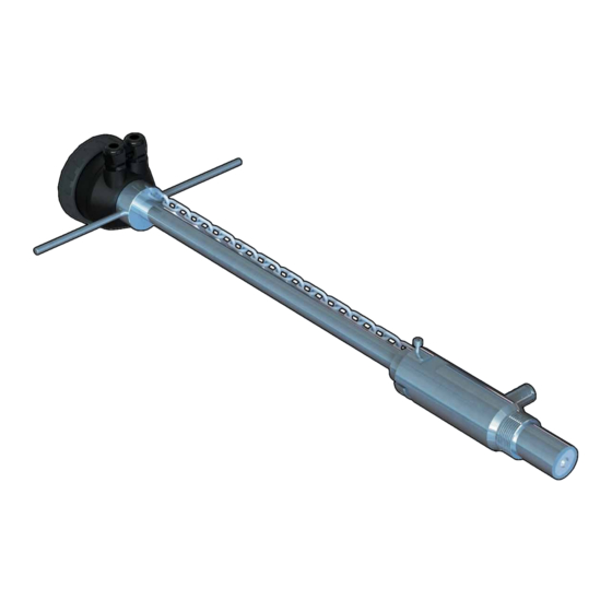
DIMENSIONS Magmeter electronic device Sliding rod AISI 304 SS joint for sensor installation Pressure intake Process connection 1 ¼” gas threaded AISI 304 SS adjustable sensor body AISI 316 L electrodes and PVDF bottom INSTALLATION Pipe Location • The six most common installation configurations shown in fig. 1 help in selecting the best location in the pipeline for paddlewheel flow sensor as well for magmeter flow sensor. - Page 6 Fig.1 Fig.2 Fig.3 Fig.4...
- Page 7 Set the sensor to work The assembly and set to work of the instrument are carried out by two simple steps that allow a quick and precise installation: 1. INSTALLATION OF THE SENSOR ON THE WET-TAP CLAMP SADDLE 2. VERTICAL POSITIONING OF THE SENSOR INTO THE PIPE Warning: the F6.61 allows installation into pressurised pipes without system shutdown;...
- Page 8 2. VERTICAL POSITIONING OF THE SENSOR INTO THE PIPE • Be sure the sensor is in the upper position. • Calculate the DISTANCE between the sliding bush C (Fig. 2) and the sensor body: DISTANCE “L” [mm] = (0.15 x Internal Diameter) +S (wall thickness) +K (distance between external pipe and end of the thread) - 15 •...
-
Page 9: General Recommendation
WIRING General recommendation Always ensure the power supply is switched off before working on the device. Make wiring connections according to wiring diagrams. • Terminals accept 26 to 12 AWG (0.08 to 2.5 mm2) • Strip around 10 mm (0.4”) of insulation from the wire tips and tin bare ends to avoid fraying. - Page 10 POWER/LOOP WIRING DIAGRAM Stand-alone application, Connection to a PLC with built-in no current loop used power supply (3 wire connection) Power Supply PLC Terminals + VDC 12 - 24 VDC + LOOP Power Supply + VDC + LOOP Power Supply 12 - 24 VDC - LOOP - LOOP...
- Page 11 SOLID-STATE RELAY WIRING DIAGRAM Connection to a PLC with NPN input Connection to a PLC with PNP input Internal PLC Internal PLC connection connection Power sup. Power sup. Power sup. Power sup. O.C. IN O.C. IN O.C. IN N.O. O.C. IN N.O.
- Page 12 OPEN COLLECTOR WIRING DIAGRAM Connection to FLS Instruments Frequency Output Direction Output - FREQ - FREQ FLS monitor FLS monitor terminals terminals + FREQ + FREQ - DIR - DIR FREQ IN + DIR FREQ IN + DIR - FREQ - FREQ FLS monitor FLS monitor...
- Page 13 EARTHING The magmeter normally is uninfluenced by low levels of electrical noise. In some applications it is necessary to connect the sensor to earth to eliminate electrical noise. The earthing can be done as following described: • connecting the Ground Wire (black wire from the sensor body) to an External Earthing passing through a cable gland.
-
Page 14: Manual Calibration
CALIBRATION Manual Calibration Manual calibration can be done setting the micro switches on PCB in the proper combination in according with the pipe size (from d20-DN15 up to d>200-DN>180) where sensor will be installed. Positions are reported in the following table. Lock position is a No Functioning Combination while the USB combination is for accessing to the USB connection. -
Page 15: Procedure For Setting
CALIBRATION BY USB The F6.61 hot tap magmeter can be connected to a PC and the operator can be connected to a PC and the operator can calibrate the instrument and set all parameters using dedicated software on USB pen drive (software can be dowloaded freely from FLS website) Procedure for setting - plug FLS Pen Drive into a USB port of PC... -
Page 16: Output Mode
OUTPUT MODE The F6.61 hot tap flow magmeter features 1 solid state relays and 1 analog output 4-20mA in addition to a Open Collector for frequency remoting (mainly for the interfacing of F6.61 with a FLS monitor) and a Open Collector for the flow direction remoting. - Page 17 F6.61 K-FACTOR TABLE (ONLY FOR FREQUENCY OUTPUT) K-Factor is the number of pulses which a sensor produces for one liter of measured fluid. Here below all K-Factors for water at room temperature are listed. K-Factor values can depend on the installation conditions. K-Factor has to divide the frequency generated by F6.61 in order to achieve the flow rate (l/s).
-
Page 18: Ordering Data
Correction formula for K-Factor calculation according to real internal diameter: K-Factor_NEW = (K-Factor x ID²) / ID_NEW² ID = Value in the table for the internal diameter (in mm) ID_NEW = New value for the real internal diameter (always in mm) K-Factor = Value in the table K-Factor_NEW = New K-Factor value for the specified internal diameter Example:... - Page 19 NOTE...
- Page 20 FIP - Formatura Iniezione Polimeri S.p.A. Loc. Pian di Parata 16015 Casella Genova - Italy Tel. +39 010 96211 Fax +39 010 9621209 www.flsnet.it...
Need help?
Do you have a question about the FLS F6.61 and is the answer not in the manual?
Questions and answers