Table of Contents
Advertisement
Quick Links
FLS M9.03
DUAL PARAMETER FLOW
MONITOR & TRANSMITTER
SAFETY INSTRUCTIONS
General Statements
• Do not install and service the product without following the Instruction
Manual.
• This item is designed to be connected to other instruments which can be
hazardous if used improperly. Read and follow all associated instrument
manuals before using with it.
• Product installation and wiring connections should only be performed by
qualified staff.
• Do not modify product construction.
Installation and Commissioning Statements
• Remove power to the instrument before wiring input and output connections.
• Do not exceed maximum specifications using the instrument.
• To clean the unit, use only chemical compatible products.
PACKING LIST
Please verify that the product is complete and without any damage.
The following items must be included:
• M9.03 Dual Parameter Flow Monitor & Transmitter
• Instruction Manual for M9.03 Dual Parameter Flow Monitor & Transmitter.
1
Advertisement
Table of Contents

Related Manuals for FIP FLS M9.03


Summary of Contents for FIP FLS M9.03
- Page 1 FLS M9.03 DUAL PARAMETER FLOW MONITOR & TRANSMITTER SAFETY INSTRUCTIONS General Statements • Do not install and service the product without following the Instruction Manual. • This item is designed to be connected to other instruments which can be hazardous if used improperly. Read and follow all associated instrument manuals before using with it.
-
Page 2: Technical Data
DESCRIPTION The new FLS M9.03 is a powerful dual flow monitor designed to convert the frequency signals of FLS flow sensors into flow rates. M9.03 is equipped with a 4” wide full graphic display which shows measured values clearly and a lot of other useful information. - Page 3 Electrical • Supply Voltage: 12 to 24 VDC ± 10% regulated • Maximum current consumption: 300 mA • FLS hall effect flow Sensor power: - 5 VDC @ < 20 mA - optically isolated from current loop - short circuit protected •...
-
Page 4: Panel Mounting
DIMENSIONS PANEL MOUNTING WALL MOUNTING... -
Page 5: Installation
INSTALLATION Mechanical installation The M9.03 Dual-Parameter Flow Monitor & Transmitter is available just in one packaging for panel or wall installation. The panel version is installed using the panel mounting kit (M9.SN1), while the wall mounting version is got fixing the panel mounting version on the wall mounting kit (M9.KWX). - Page 6 Wall installation Use the panel mounting kit (M9.SN1) to fix the M9.03 on the dedicated frontal cutout of the wall mounting kit (M9.KWX). Tighten front screws of box and waterproof connectors of cables, internally mount caps on screw sites to get a IP65 watertight installation.
- Page 7 WIRING General recommendation Always ensure the power supply is switched off before working on the device. Make wiring connections according to wiring diagrams. • Terminals accept 26 to 12 AWG (0.08 to 2.5 mm2) • Strip around 10 mm (0.4”) of insulation from the wire tips and tin bare ends to avoid fraying.
- Page 8 POWER/LOOP WIRING DIAGRAM Stand-alone application, Connection to a PLC with built-in no current loop used power supply Power Supply PLC Terminals 12 - 24 VDC + VDC Power Supply + VDC - VDC 12 - 24 VDC 12 - 24 VDC - VDC 4 - 20 mA - LOOP 2...
- Page 9 Connection to a PLC / Instrument Connection to a PLC / Instrument digital input with separate Power digital input for Voltage Free Contacts Supply (REED) Power Supply DIGITAL INPUT N 12 - 24 VDC 12 - 24 VDC N.O. PLC / Instrument DIGITAL INPUT 2 Imax Digital INPUT...
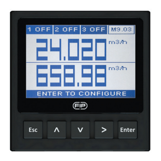
- Page 10 MENU DIRECTORY OPERATIONAL OVERVIEW The M9.03 Dual Parameter Flow Monitor Settings 1 and Transmitterfeatures a full graphic display and a five-button keypad for system set-up, calibration and operation. Full graphic display has a white backlight during standard conditions, a red backlight in case a set alarm is activated (MAX, Settings 2 MIN, WINDOW IN, WINDOW OUT MODE:...
- Page 11 MENU LEVEL Settings 1 Installation Data Volume Unit Flow Unit Settings 2 Installation Data Volume Unit Flow Unit Calibration 1 Correction Factor Signal Intensity BLE Auto Calibration Calibration 2 Correction Factor Signal Intensity BLE Auto Calibration Outputs 1 SSR Output Test 2 SSR 4-20mA 3 RELAY...
-
Page 12: Output Mode
EDIT LEVEL PUSH BUTTON to modify an item to scroll right to return to Menu without saving to save new settings OUTPUT MODE The M9.03 Dual Parameter Flow Monitor and Transmitter features 2 solid state relays and 2 mechanical relays in addition to 2 analog outputs 4-20mA. PROCEDURE FOR OUTPUTS SETTING •... - Page 13 Digital outputs can be set in the following way: MIN MODE (icon reports MIN) MAX MODE (icon reports MAX) Flow Flow Hysteresis Setpoint Setpoint Hysteresis Output relaxed Time Time Output relaxed Output energized Output energized PULSE MODE (icon reports PLS) Pulse duration Pulse duration Pulse duration...
-
Page 14: Software Updating
OUTPUT FOR F3.00.W In case of combination with F3.00.W, LOW BATTERY status and NO SIGNAL condition can be remoted by two different digital outputs or by one for both indications. SOFTWARE UPDATING In order to update the Instrument Software with a New Firmware Release follow the suggested procedures TO UPDATE INSTALLED UNITS - Download the interface software “FLS Calibration System”... -
Page 15: Ordering Data
ORDERING DATA Description Power Wire power Sensor Part No. Output /Name supply Technology Input Panel mount Dual 2*(4-20mA), Parameter 2* Flow M9.03.P1 12 - 24 VDC 3/4 wire 2*(S.S.R.), Flow (Frequency) 2*(mech. relay) Monitor and Transmitter Wall mount Flow Monitor Dual 2*(4-20mA), 2* Flow... - Page 16 FIP - Formatura Iniezione Polimeri S.p.A. Loc. Pian di Parata 16015 Casella Genova - Italy Tel. +39 010 96211 Fax +39 010 9621209 www.flsnet.it...
Need help?
Do you have a question about the FLS M9.03 and is the answer not in the manual?
Questions and answers